Page 17 of 661

2-4
Vehicle Information, Consumer Information and Reporting Safety Defects
The actual shape may differ from the illustration.
A0003EU01
1. Inside door handle .................................5-32
2. Side view mirror control switch ........... 5-58
3. Central door lock switch ...................... 5-33
4. Power window switches ...................... 5-66
5. Power window lock button/
Electronic child safety lock button ...... 5-69
6. Instrument panel illumination controlswitch .......................................... 4-5
7. Towing button .......................................6-60 8. ESC (Electronic Stability Control) OFF
button .................................................... 6-38
9. Power liftgate open/close button ....... 5-87
10. EPB (Electronic Parking Brake) switch . 6-28
11. Hood release lever ................................ 5-82
12. Steering wheel tilt/telescopic lever .... 5-45
13. Steering wheel ...................................... 5-46
14. Seat .......................................................... 3-3
15. Fuse box ................................................ 9-46
INTERIOR OVERVIEW
Page 20 of 661
2-7
02
The actual engine compartment in the vehicle may differ from the illustration.
A0419KO02
1. Engine coolant reservoir ........................ 9-3
2. Radiator cap ...........................................9-18
3. Brake fluid reservoir .............................. 9-21
4. Air cleaner ............................................. 9-23
5. Engine oil filler cap ................................ 9-156. Engine oil dipstick ................................. 9-15
7. Windshield washer fluid reservoir ....... 9-22
8. Fuse/relay box ...................................... 9-46
9. Battery ................................................... 9-28
ENGINE COMPARTMENT
Page 567 of 661

08
8-5
Jump starting procedure
1. Position the vehicles close enough that the jumper cables will reach, but
do not allow the vehicles to touch.
2. Avoid fans or any moving parts in the engine compartment at all times, even
when the vehicles are turned off.
3. Turn off all electrical devices such as radios, lights, air conditioning, etc.
Put the vehicles in P (Park) and set the
parking brake. Turn both vehicles OFF.
4. Open the engine hood.
5. Remove the engine compartment fuse box cover.
CAUTION
Before jump starting, make sure to
correctly identify the positive (+) and
negative (-) terminals to avoid reverse
polarity connections.
B0401KO01
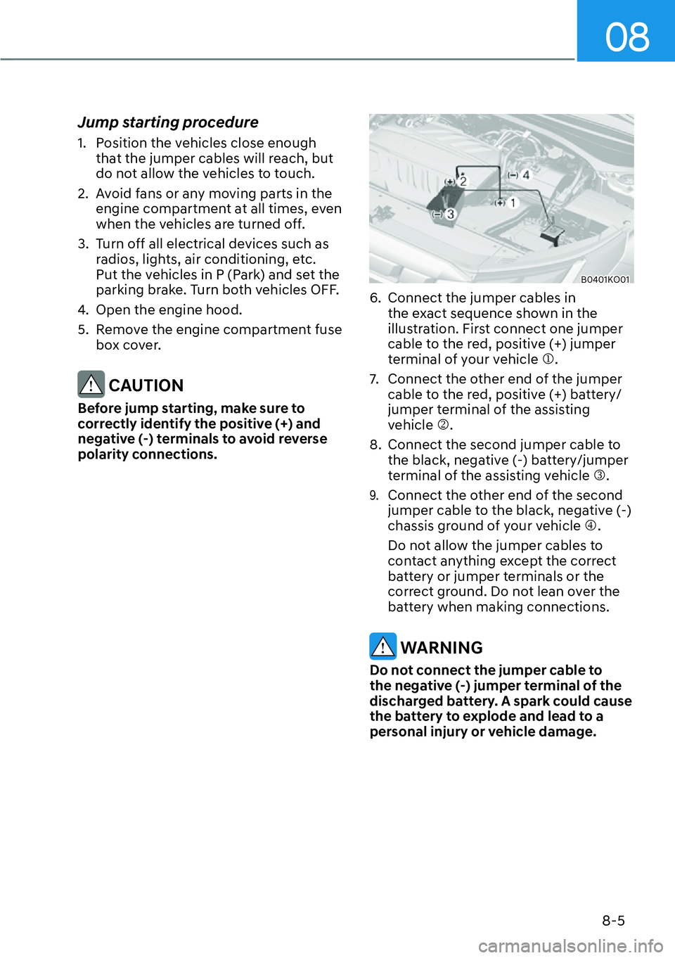
6. Connect the jumper cables in the exact sequence shown in the
illustration. First connect one jumper
cable to the red, positive (+) jumper
terminal of your vehicle �M.
7. Connect the other end of the jumper cable to the red, positive (+) battery/
jumper terminal of the assisting
vehicle �N.
8. Connect the second jumper cable to the black, negative (-) battery/jumper
terminal of the assisting vehicle �O.
9. Connect the other end of the second
jumper cable to the black, negative (-)
chassis ground of your vehicle �P.
Do not allow the jumper cables to
contact anything except the correct
battery or jumper terminals or the
correct ground. Do not lean over the
battery when making connections.
WARNING
Do not connect the jumper cable to
the negative (-) jumper terminal of the
discharged battery. A spark could cause
the battery to explode and lead to a
personal injury or vehicle damage.
Page 590 of 661
9-3
09
The actual engine compartment in the vehicle may differ from the illustration.
A0419KO02
1. Engine coolant reservoir
2. Radiator cap
3. Brake fluid reservoir
4. Air cleaner
5. Engine oil filler cap6. Engine oil dipstick
7. Windshield washer fluid reservoir
8. Fuse/relay box
9. Battery
ENGINE COMPARTMENT
Page 635 of 661
Maintenance9-48
Fuse/Relay Panel Description
Instrument panel fuse panel
B0469KO01
Inside the fuse/relay box cover, you can
find the fuse/relay label describing fuse/
relay names and ratings.
Information
Not all fuse panel descriptions in this
manual may be applicable to your vehicle;
the information is accurate at the time of
printing. When you inspect the fuse box on
your vehicle, refer to the fuse box label.
A0467EU01
Page 637 of 661

Maintenance9-50
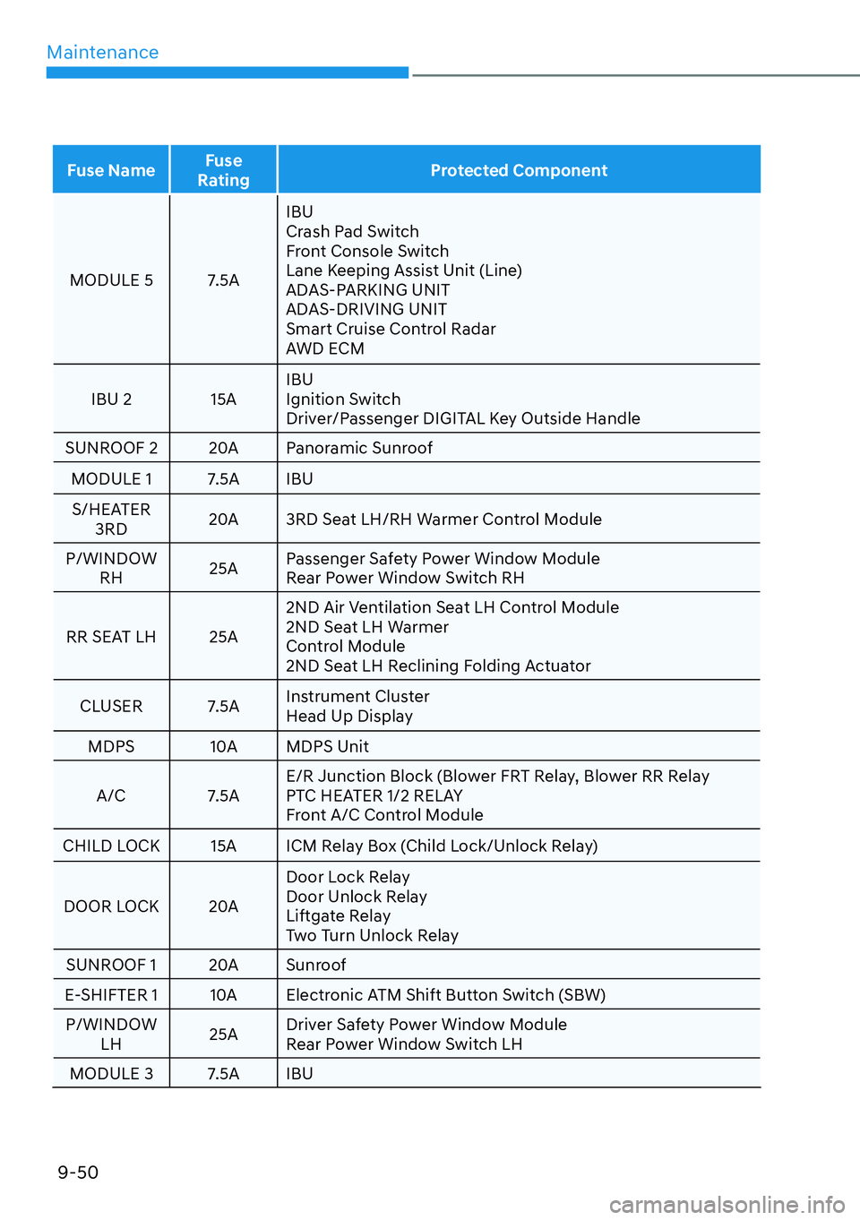
Fuse Name Fuse
Rating Protected Component
MODULE 5 7.5A IBU
Cr
ash Pad Switch
Front Console Switch
Lane Keeping Assist Unit (Line)
ADAS-PARKING UNIT
ADAS-DRIVING UNIT
Smart Cruise Control Radar
AWD ECM
IBU 2 15A IBU
Ignition Switch
Driver/Passenger DIGITAL Key Outside Handle
SUNROOF 2 20A Panoramic Sunroof
MODULE 1 7.5A IBUS/HEATER 3RD 20A 3RD Seat LH/RH Warmer Control Module
P/WINDOW RH 25APassenger Safety Power Window Module
Rear Power Window Switch RH
RR SEAT LH 25A 2ND Air Ventilation Seat LH Control Module
2ND Seat LH Warmer
Control Module
2ND Seat LH Reclining Folding Actuator
CLUSER 7.5A Instrument Cluster
Head Up Display
MDPS 10A MDPS Unit
A/C 7.5A E/R Junction Block (Blower FRT Relay, Blower RR Relay
PTC HEATER 1/2 RELAY
Front A/C Control Module
CHILD LOCK 15A ICM Relay Box (Child Lock/Unlock Relay)
DOOR LOCK 20A Door Lock Relay
Door Unlock Relay
Liftgate Relay
Two Turn Unlock Relay
SUNROOF 1 20A Sunroof
E-SHIFTER 1 10A Electronic ATM Shift Button Switch (SBW) P/WINDOW LH 25ADriver Safety Power Window Module
Rear Power Window Switch LH
MODULE 3 7.5A IBU
Page 639 of 661
Maintenance9-52
Engine compartment fuse panel
(Engine room junction block)
B0469KO03
Inside the fuse/relay box cover, you can
find the fuse/relay label describing fuse/
relay names and ratings.
Information
Not all fuse panel descriptions in this
manual may be applicable to your vehicle;
the information is accurate at the time of
printing. When you inspect the fuse panel
in your vehicle, refer to the fuse panel
label.
A0468EU01