Page 489 of 558
7-65
7
Maintenance
Bright-metal maintenance
To remove road tar and insects,use a tar remover, not a scraper or
other sharp object.
To protect the surfaces of bright- metal parts from corrosion, apply a
coating of wax or chrome preser-
vative and rub to a high luster.
During winter weather or in coastal areas, cover the bright metal parts
with a heavier coating of wax or
preservative. If necessary, coat the
parts with non-corrosive petroleum
jelly or other protective compound.
Underbody maintenance
Corrosive materials used for ice and
snow removal and dust control may
collect on the underbody. If these
materials are not removed, acceler-
ated rusting can occur on underbody
parts such as the fuel lines, frame,
floor pan and exhaust system, even
though they have been treated with
rust protection. Thoroughly flush the vehicle under-
body and wheel openings with luke-
warm or cold water once a month,
after off-road driving and at the end
of each winter. Pay special attentionto these areas because it is difficult
to see all the mud and dirt. It will do
more harm than good to wet down
the road grime without removing it.
The lower edges of doors, rocker
panels, and frame members have
drain holes that should not be
allowed to clog with dirt; trapped
water in these areas can cause rust-ing.
Aluminum wheel maintenance
The aluminum wheels are coated
with a clear protective finish.
Do not use abrasive cleaner, pol-
ishing compound, solvent, or
wire brushes on aluminumwheels.
Clean the wheel when it has cooled.
Use only a mild soap or neutral detergent, and rinse thoroughly
with water. Also, clean thewheels after driving on salted
roads.
Do not wash the wheels with high-speed car wash brushes.
Do not use any cleaners con- taining acid or alkaline deter-
gents.
NOTICE
After washing the vehicle, test
the brakes while driving slowly
to see if they have been affected
by water. If braking performance
is impaired, dry the brakes by
applying them lightly while
maintaining a slow forwardspeed.
WARNING
Page 499 of 558
8-6
Specifications and Reporting Safety DefectsR
R EECCOO MM MMEENN DDEEDD LL UU BBRRIICC AA NN TTSS AA NN DD CC AA PPAA CCIITT IIEE SS
To help achieve proper vehicle performance and durability, use only lubricants of the proper quality.
These lubricants and fluids are recommended for use in your vehicle.
Lubricant Volume Classification
Reduction gear fluid 1
l(1.06 US qt)
GL4 75W/85, TGO-9
Coolant Fuel cell stack
We recommend that you consult an authorized Hyundai dealer.
Traction motor
Brake fluid Amount required SAE J1704 DOT-4LV,
FMVSS116 DOT-4,ISO4925 CLASS-6
Fuel 156.6
l(165.48 US qt.)
Hydrogen (SAE J2719 or ISO 14687-2)
Page 503 of 558
Introduction of FCEV .........................................................H2
The components of FCEV..................................................H3Fuel cell stack ..................................................................................H4
FCEV powertrain...............................................................................H4
High pressure hydrogen storage tanks ......................................H5
Battery system..................................................................................H5
Features of FCEV .............................................................H10 How to Start the Vehicle ..............................................................H10
How to Stop the Vehicle ..............................................................H11
Virtual Engine Sound System......................................................H11
Fuel filler door ................................................................................H12
Warning and indicator lights .......................................................H15
LCD Display Messages ..................................................................H16
FCEV mode.......................................................................................H21
When the high voltage battery is weak ...................................H25
If the 12 volt battery is discharged...........................................H25
Emergency while driving ..............................................................H26
Customer Q&A Guide .......................................................H30
FF CC EE VV VV eehh iicc llee SS yyssttee mm OO vvee rrvv iiee ww
FCEV : Fuel Cell Electric Vehicle
Page 504 of 558
H2
An FCEV is an electric vehicle which is driven using the electricity generated from the fuel cell.
The power system of the FCEV is composed of the following:
- The fuel cell stack which generates the electricity
- The device which controls the heat generated after supplying the hydrogen and air for chemical reaction of the stack
- The inverter which converts the DC created from the stack to AC
- The traction motor which generates propelling power using the supplied AC- Air processing system- Fuel processing system
The hydrogen tanks that stores the hydrogen supplied to the fuel cell can be fueled at 70 MPa. ❈FCEV is Fuel Cell Electric Vehicle
IINN TTRR OO DDUU CCTT IIOO NN OO FF FF CC EE VV
Page 505 of 558
H3
TTHH EE CC OO MM PPOO NNEENN TTSS OO FF FF CC EE VV
OFEQ018001N/OFEQ018002/OFEQ018003/OFEQ018004/OFEQ018005
(1) Fuel Cell system
(2) Traction motor system (3) Hydrogen Tanks
(4) Battery System
12
34
Page 506 of 558
H4
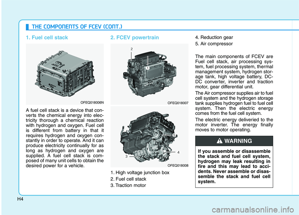
1. Fuel cell stack
A fuel cell stack is a device that con-
verts the chemical energy into elec-
tricity thorough a chemical reaction
with hydrogen and oxygen. Fuel cell
is different from battery in that it
requires hydrogen and oxygen con-
stantly in order to operate. And it can
produce electricity continually for as
long as hydrogen and oxygen are
supplied. A fuel cell stack is com-
posed of many unit cells to obtain the
desired power for a vehicle.
2. FCEV powertrain
1. High voltage junction box
2. Fuel cell stack
3. Traction motor4. Reduction gear
5. Air compressor The main components of FCEV are
Fuel cell stack, air processing sys-
tem, fuel processing system, thermal
management system, hydrogen stor-
age tank, high voltage battery, DC-
DC converter, inverter and traction
motor, gear differential unit. The Air compressor supplies air to fuel
cell system and the hydrogen storage
tank supplies hydrogen fuel to fuel cell
system. Then the electric energycomes from the fuel cell system.
The electric energy deliveried to the
motor inverter. The energy finally
moves to motor operating.
TT
HH EE CC OO MM PPOO NNEENN TTSS OO FF FF CC EE VV (( CC OO NNTT..))
OFEQ018006NOFEQ018007
OFEQ018008
If you assemble or disassemble
the stack and fuel cell system,
hydrogen may leak resulting in
fire and this may lead to acci-
dents. Never assemble or disas-
semble the stack and fuel cellsystem.
WARNING
Page 507 of 558
H5
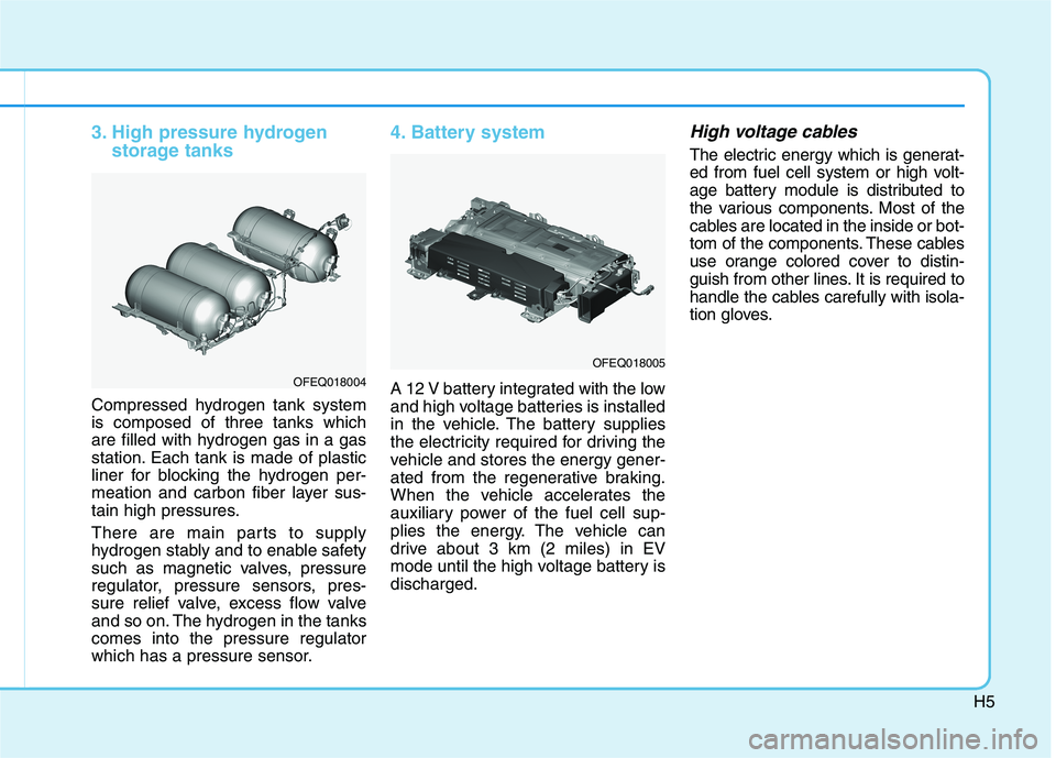
3. High pressure hydrogenstorage tanks
Compressed hydrogen tank system is composed of three tanks which
are filled with hydrogen gas in a gas
station. Each tank is made of plastic
liner for blocking the hydrogen per-
meation and carbon fiber layer sus-
tain high pressures.
There are main parts to supply
hydrogen stably and to enable safety
such as magnetic valves, pressure
regulator, pressure sensors, pres-
sure relief valve, excess flow valve
and so on. The hydrogen in the tankscomes into the pressure regulator
which has a pressure sensor.
4. Battery system
A 12 V battery integrated with the low
and high voltage batteries is installed
in the vehicle. The battery supplies
the electricity required for driving the
vehicle and stores the energy gener-
ated from the regenerative braking.
When the vehicle accelerates the
auxiliary power of the fuel cell sup-
plies the energy. The vehicle can
drive about 3 km (2 miles) in EV
mode until the high voltage battery isdischarged.
High voltage cables
The electric energy which is generat-
ed from fuel cell system or high volt-
age battery module is distributed to
the various components. Most of the
cables are located in the inside or bot-
tom of the components. These cables
use orange colored cover to distin-
guish from other lines. It is required to
handle the cables carefully with isola-
tion gloves.
OFEQ018004
OFEQ018005
Page 508 of 558
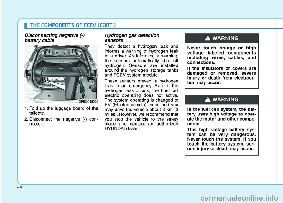
H6
Disconnecting negative (-) battery cable
1. Fold up the luggage board of the tailgate.
2. Disconnect the negative (-) con- nector.
Hydrogen gas detection
sensors
They detect a hydrogen leak and
informs a warning of hydrogen leak
to a driver. As informing a warning,the sensors automatically shut off
hydrogen. Sensors are installed
around the hydrogen storage tanks
and FCEV system module.
These sensors prevent a hydrogen
leak in an emergency. Even if the
hydrogen leak occurs, the Fuel cell
electric operating does not active.
The system operating is changed to
EV (Electric vehicle) mode and you
may drive the vehicle about 3 km (2
miles). However, we recommend that
you stop the vehicle to the safety
place and contact an authorized
HYUNDAI dealer.
OFEQ018009
TT HH EE CC OO MM PPOO NNEENN TTSS OO FF FF CC EE VV (( CC OO NNTT..))
Never touch orange or high
voltage labeled components
including wires, cables, andconnections.
If the insulators or covers are
damaged or removed, severe
injury or death from electrocu-
tion may occur.
WARNING
In the fuel cell system, the bat-
tery uses high voltage to oper-ate the motor and other compo-nents.
This high voltage battery sys-
tem can be very dangerous.
Never touch the system. If you
touch the battery system, seri-
ous injury or death may occur.
WARNING