Page 284 of 558
5-17
Driving your vehicle
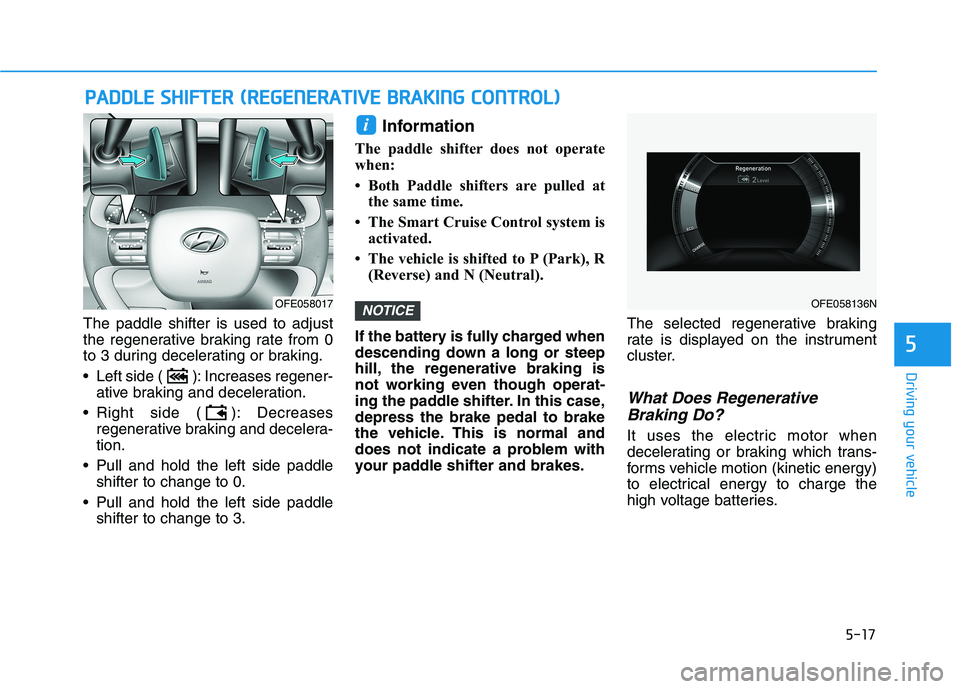
The paddle shifter is used to adjust
the regenerative braking rate from 0
to 3 during decelerating or braking.
Left side ( ): Increases regener-ative braking and deceleration.
Right side ( ): Decreases regenerative braking and decelera- tion.
Pull and hold the left side paddle shifter to change to 0.
Pull and hold the left side paddle shifter to change to 3. Information
The paddle shifter does not operate
when:
Both Paddle shifters are pulled at the same time.
The Smart Cruise Control system is activated.
The vehicle is shifted to P (Park), R (Reverse) and N (Neutral).
If the battery is fully charged when
descending down a long or steep
hill, the regenerative braking is
not working even though operat-
ing the paddle shifter. In this case,depress the brake pedal to brake
the vehicle. This is normal and
does not indicate a problem with
your paddle shifter and brakes. The selected regenerative braking
rate is displayed on the instrument
cluster.
What Does Regenerative
Braking Do?
It uses the electric motor when
decelerating or braking which trans-
forms vehicle motion (kinetic energy)
to electrical energy to charge the
high voltage batteries.
NOTICE
i
PP AA DDDDLLEE SS HH IIFF TT EERR (( RR EEGG EENN EERR AA TTIIVV EE BB RRAA KKIINN GG CC OO NNTTRR OO LL))
5
OFE058136NOFE058017
Page 325 of 558
5-58
Driving your vehicle
Blind-Spot Collision-AvoidanceAssist (BCA) system
The Blind-Spot Collision-Avoidance
Assist (BCA) system may apply brak-
ing power, when an approaching
vehicle is detected within a certain
distance next to or behind your vehi-
cle.
It gently applies braking power on
the tire, which is located in the oppo-
site side of the possibly-colliding
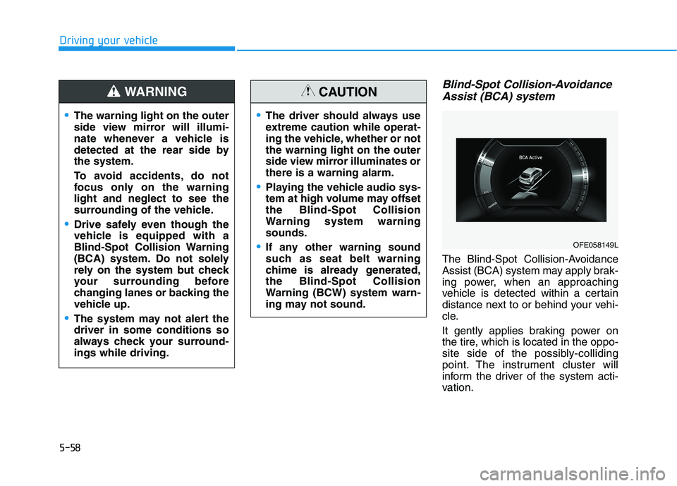
point. The instrument cluster will
inform the driver of the system acti-
vation.
The warning light on the outer
side view mirror will illumi-
nate whenever a vehicle is
detected at the rear side bythe system.
To avoid accidents, do not
focus only on the warninglight and neglect to see the
surrounding of the vehicle.
Drive safely even though the
vehicle is equipped with a
Blind-Spot Collision Warning
(BCA) system. Do not solely
rely on the system but check
your surrounding before
changing lanes or backing the
vehicle up.
The system may not alert the driver in some conditions so
always check your surround-ings while driving.
WARNING
The driver should always use
extreme caution while operat-
ing the vehicle, whether or notthe warning light on the outer
side view mirror illuminates orthere is a warning alarm.
Playing the vehicle audio sys-
tem at high volume may offsetthe Blind-Spot Collision
Warning system warningsounds.
If any other warning sound
such as seat belt warning
chime is already generated,the Blind-Spot Collision
Warning (BCW) system warn-
ing may not sound.
CAUTION
OFE058149L
Page 337 of 558
5-70
Driving your vehicle
Rear Cross-Traffic Collision-Avoidance Assist (RCCA)
systemIf the risk of collision is detected
while the RCCW is generated, brake
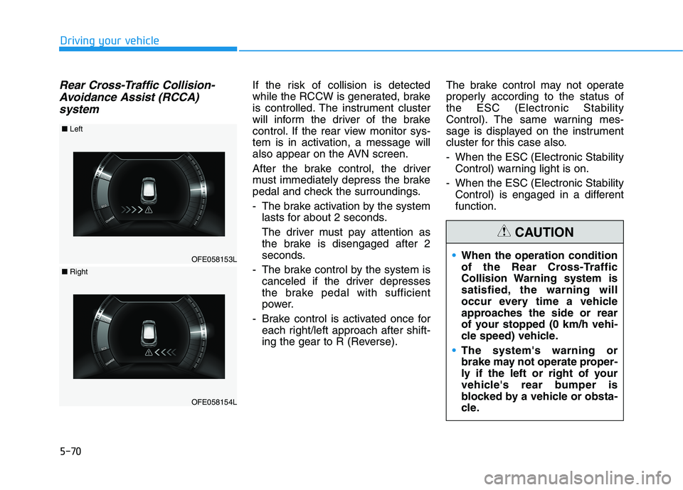
is controlled. The instrument cluster
will inform the driver of the brake
control. If the rear view monitor sys-
tem is in activation, a message will
also appear on the AVN screen.
After the brake control, the driver
must immediately depress the brake
pedal and check the surroundings.
- The brake activation by the system lasts for about 2 seconds.
The driver must pay attention as
the brake is disengaged after 2
seconds.
- The brake control by the system is canceled if the driver depresses
the brake pedal with sufficient
power.
- Brake control is activated once for each right/left approach after shift-
ing the gear to R (Reverse). The brake control may not operate
properly according to the status ofthe ESC (Electronic Stability
Control). The same warning mes-
sage is displayed on the instrument
cluster for this case also.
- When the ESC (Electronic Stability
Control) warning light is on.
- When the ESC (Electronic Stability Control) is engaged in a different function.
OFE058153L
■Left
OFE058154L
■Right
When the operation condition
of the Rear Cross-Traffic
Collision Warning system is
satisfied, the warning will
occur every time a vehicle
approaches the side or rear
of your stopped (0 km/h vehi-
cle speed) vehicle.
The system's warning or
brake may not operate proper-
ly if the left or right of your
vehicle's rear bumper is
blocked by a vehicle or obsta-
cle.
CAUTION
Page 348 of 558
5-81
Driving your vehicle
5
LKA System Operation
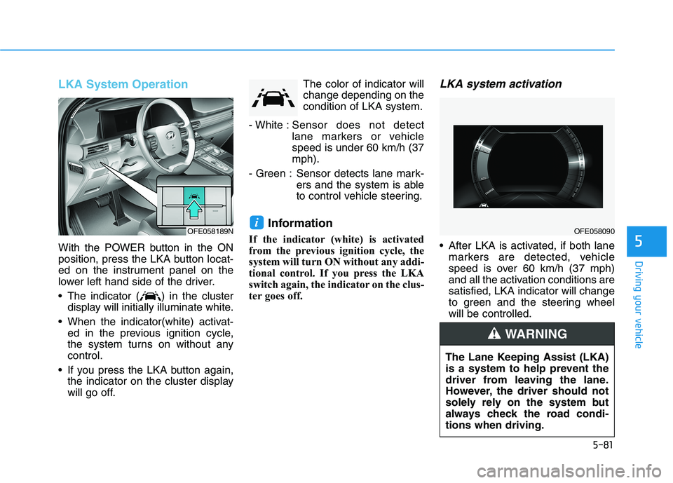
With the POWER button in the ON
position, press the LKA button locat-
ed on the instrument panel on the
lower left hand side of the driver.
The indicator ( ) in the clusterdisplay will initially illuminate white.
When the indicator(white) activat- ed in the previous ignition cycle,
the system turns on without anycontrol.
If you press the LKA button again, the indicator on the cluster display
will go off. The color of indicator willchange depending on thecondition of LKA system.
- White : Sensor does not detect
lane markers or vehiclespeed is under 60 km/h (37mph).
- Green : Sensor detects lane mark- ers and the system is able
to control vehicle steering.
Information
If the indicator (white) is activated
from the previous ignition cycle, the
system will turn ON without any addi-
tional control. If you press the LKA
switch again, the indicator on the clus-
ter goes off.
LKA system activation
After LKA is activated, if both lane markers are detected, vehicle
speed is over 60 km/h (37 mph)
and all the activation conditions aresatisfied, LKA indicator will change
to green and the steering wheelwill be controlled.
iOFE058189NOFE058090
The Lane Keeping Assist (LKA)
is a system to help prevent the
driver from leaving the lane.
However, the driver should not
solely rely on the system but
always check the road condi-tions when driving.
WARNING
Page 474 of 558
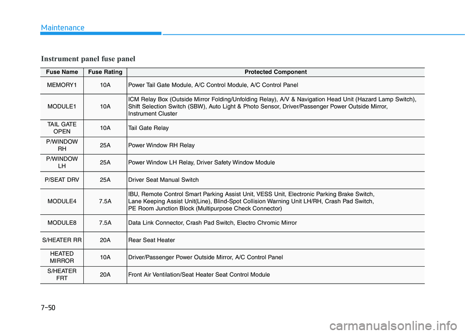
7-50
Maintenance
Fuse NameFuse RatingProtected Component
MEMORY110APower Tail Gate Module, A/C Control Module, A/C Control Panel
MODULE110AICM Relay Box (Outside Mirror Folding/Unfolding Relay), A/V & Navigation Head Unit (Hazard Lamp Switch),
Shift Selection Switch (SBW), Auto Light & Photo Sensor, Driver/Passenger Power Outside Mirror,
Instrument Cluster
TAIL GATEOPEN10ATail Gate Relay
P/WINDOW RH25APower Window RH Relay
P/WINDOW LH25APower Window LH Relay, Driver Safety Window Module
P/SEAT DRV25ADriver Seat Manual Switch
MODULE47.5AIBU, Remote Control Smart Parking Assist Unit, VESS Unit, Electronic Parking Brake Switch,
Lane Keeping Assist Unit(Line), Blind-Spot Collision Warning Unit LH/RH, Crash Pad Switch,
PE Room Junction Block (Multipurpose Check Connector)
MODULE87.5AData Link Connector, Crash Pad Switch, Electro Chromic Mirror
S/HEATER RR20ARear Seat Heater
HEATED
MIRROR10ADriver/Passenger Power Outside Mirror, A/C Control Panel
S/HEATER FRT20AFront Air Ventilation/Seat Heater Seat Control Module
Instrument panel fuse panel
Page 475 of 558
7-51
7
Maintenance
Fuse NameFuse RatingProtected Component
AMP25AAMP
MULTI MEDIA15AA/V & Navigation Head Unit, Center Fascia Switch Panel
MODULE510AFront Air Ventilation/Seat Heater Seat Control Module, AMP, A/V & Navigation Head Unit,
A/C Control Panel, PTC Heater, A/C Control Module, Electro Chromic Mirror, Rear Seat Heater
WIPER (RR)15AICM Relay Box (Rear Wiper Relay), Rear Wiper Motor
DOOR LOCK20ADoor Lock Relay, Door Unlock Relay, ICM Relay Box (Two Turn Door Unlock Relay)
IBU115AIBU
BRAKE
SWITCH10AIBU, Stop Lamp Switch
P/SEAT PASS25APassenger Seat Manual Switch
A/C7.5AA/C Control Module, Incar Temperature Sensor, A/C Control Panel,
Cluster Ionizer, A/C Compressor, PE Room Junction Block (Blower Relay)
AIR BAG210ASRS Control Module
WASHER15AMultifunction Switch
Instrument panel fuse panel
Page 476 of 558
7-52
Maintenance
Fuse NameFuse RatingProtected Component
MDPS7.5AMDPS Unit
MODULE77.5AFront Air Ventilation/Seat Heater Seat Control Module, AC Inverter,
Rear Seat Heater, Surround View Monitor Unit, Rear Power Outlet
SUNROOF220ASunroof Unit
SUNROOF120ASunroof Unit
CLUSTER7.5AInstrument Cluster
MODULE37.5ASCU, Shift Selection Switch (SBW), IDC, VPD Sensor, Stop Lamp Switch, HMU, BMS Control Module
START7.5AFCU, IBU
IBU27.5AIBU
A/BAG IND7.5AInstrument Cluster, A/C Control Panel
MODULE67.5AIBU
MODULE210ABMS Control Module, Wireless Charger, USB Charger LH/RH, A/V & Navigation Head Unit,
Center Fascia Switch Panel, AMP, Surround View Monitor Unit, Power Outside Mirror Switch, IBU
AIR BAG115ASRS Control Module, Passenger Occupant Detection Sensor
Instrument panel fuse panel
Page 513 of 558

H11
How to Stop the Vehicle
1. Hold down the brake pedal whilethe vehicle is parked.
2. While depressing the brake pedal, shift to P (Park).
3. While depressing the brake pedal, engage the parking brake.
4. While depressing the brake pedal, press the Power button and turn
off the vehicle.
5. Check if the " " indicator is turned OFF on the instrument
cluster.
When the " " indicator is ON and the gear is in a position other
than P (Park), the driver can acci-
dently depress the accelerator
pedal, causing the vehicle to move
unexpectedly.
Virtual Engine Sound System
The Virtual Engine Sound System
generates engine sound for pedestri-
ans to hear vehicle sound becausethere is no sound while the FCEV
vehicle is operating.
• If the vehicle is in the ready ( ) mode and the gear is not in P
(Park),
When the gear is shifted to R (Reverse), an additional warningsound will be heard.
•The vehicle is much quieter
while driving than a conven-
tional gasoline-powered vehi-
cle. Be aware of your sur-
roundings and always drive
safely.
After you park the vehicle or
while you are waiting at a traf-
fic light, check whether there
are children or obstacles
around the vehicle.
Check if there is something
behind the vehicle when driv-
ing in reverse. Pedestrians
may not hear the sound of the
vehicle.
CAUTION