2023 HYUNDAI KONA EV sensor
[x] Cancel search: sensorPage 463 of 548
Emergency situations
8-8
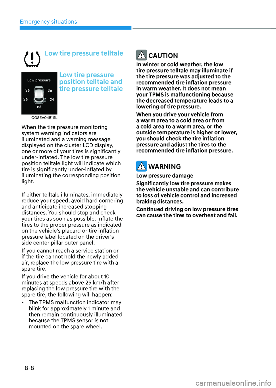
Low tire pressure telltale
OOSEV048111L
Low tire pressure
position telltale and
tire pressure telltale
When the tire pressure monitoring
system warning indicators are
illuminated and a warning message
displayed on the cluster LCD display,
one or more of your tires is significantly
under-inflated. The low tire pressure
position telltale light will indicate which
tire is significantly under-inflated by
illuminating the corresponding position
light.
If either telltale illuminates, immediately
reduce your speed, avoid hard cornering
and anticipate increased stopping
distances. You should stop and check
your tires as soon as possible. Inflate the
tires to the proper pressure as indicated
on the vehicle’s placard or tire inflation
pressure label located on the driver’s
side center pillar outer panel.
If you cannot reach a service station or
if the tire cannot hold the newly added
air, replace the low pressure tire with a
spare tire.
If you drive the vehicle for about 10
minutes at speeds above 25 km/h after
replacing the low pressure tire with the
spare tire, the following will happen: • The TPMS malfunction indicator may
blink for approximately 1 minute and
then remain continuously illuminated
because the TPMS sensor is not
mounted on the spare wheel.
CAUTION
In winter or cold weather, the low
tire pressure telltale may illuminate if
the tire pressure was adjusted to the
recommended tire inflation pressure
in warm weather. It does not mean
your TPMS is malfunctioning because
the decreased temperature leads to a
lowering of tire pressure.
When you drive your vehicle from
a warm area to a cold area or from
a cold area to a warm area, or the
outside temperature is higher or lower,
you should check the tire inflation
pressure and adjust the tires to the
recommended tire inflation pressure.
WARNING
Low pressure damage
Significantly low tire pressure makes
the vehicle unstable and can contribute
to loss of vehicle control and increased
braking distances.
Continued driving on low pressure tires
can cause the tires to overheat and fail.
Page 464 of 548
08
8-9
TPMS (Tire Pressure
Monitoring System)
malfunction indicator
The TPMS malfunction indicator
will illuminate after it blinks for
approximately one minute when there
is a problem with the Tire Pressure
Monitoring System.
We recommend that the system be
checked by an authorized HYUNDAI
dealer.
NOTICE
If there is a malfunction with the TPMS,
the Low Tire Pressure Position Telltale
will not be displayed even though the
vehicle has an under-inflated tire.
NOTICE
The TPMS Malfunction Indicator may
illuminate after blinking for one minute
if the vehicle is near electric power
supply cables or radio transmitters
such as police stations, government
and public offices, broadcasting
stations, military installations, airports,
transmitting towers, etc.
Additionally, the TPMS Malfunction
Indicator may illuminate if snow chains
are used or electronic devices such as
computers, chargers, remote starters,
navigation, etc. This may interfere with
normal operation of the TPMS.
Changing a tire with TPMS
If you have a flat tire, the Low Tire
Pressure and Position telltales will come
on. We recommend that the flat tire be
repaired by an authorized HYUNDAI
dealer as soon as possible or replace the
flat tire with the spare tire.
CAUTION
It is recommended that you do not use a
puncture-repairing agent not approved
by HYUNDAI dealer to repair and/or
inflate a low pressure tire. Tire sealant
not approved by HYUNDAI dealer may
damage the tire pressure sensor.
Once the original tire equipped with
a tire pressure monitoring sensor is
reinflated to the recommended pressure
and reinstalled on the vehicle, the
Low Tire Pressure Telltale and TPMS
Malfunction Indicator will go off within a
few minutes of driving.
Each wheel is equipped with a tire
pressure sensor mounted inside
the tire behind the valve stem. You
must use TPMS specific wheels. It is
recommended that you have your tires
serviced by an authorized HYUNDAI
dealer.
If the indicators do not extinguish after
a few minutes, we recommend that you
visit an authorized HYUNDAI dealer.
You may not be able to identify a tire
with low pressure by simply looking at it.
Always use a good quality tire pressure
gauge to measure. Please note that a tire
that is hot (from being driven) will have a
higher pressure measurement than a tire
that is cold.
A cold tire means the vehicle has been
sitting for 3 hours and driven for less
than 1.6 km (1 mile) in that 3 hour period.
Allow the tire to cool before measuring
the inflation pressure. Always be sure
the tire is cold before inflating to the
recommended pressure.
Page 470 of 548
08
8-15
OIGH067043
OOSEV060007L
10. After driving approximately 7~10 km (4~6 miles or about 10 min), stop at a
safety location.
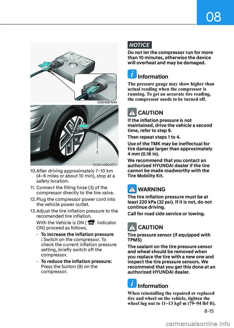
11. Connect the filling hose (3) of the compressor directly to the tire valve.
12. Plug the compressor power cord into the vehicle power outlet.
13. Adjust the tire inflation pressure to the recomended tire inflation.
With the Vehicle is ON (
indicator
ON) proceed as follows.
- To increase the inflation pressure : Switch on the compressor. To
check the current inflation pressure
setting, briefly switch off the
compressor.
- To reduce the inflation pressure:
Press the button (9) on the
compressor.
NOTICE
Do not let the compressor run for more
than 10 minutes, otherwise the device
will overheat and may be damaged.
Information
The pressure gauge may show higher than
actual reading when the compressor is
running. To get an accurate tire reading,
the compressor needs to be turned off.
CAUTION
If the inflation pressure is not
maintained, drive the vehicle a second
time, refer to step 9.
Then repeat steps 1 to 4.
Use of the TMK may be ineffectual for
tire damage larger than approximately
4 mm (0.16 in).
We recommend that you contact an
authorized HYUNDAI dealer if the tire
cannot be made roadworthy with the
Tire Mobility Kit.
WARNING
The tire inflation pressure must be at
least 220 kPa (32 psi). If it is not, do not
continue driving.
Call for road side service or towing.
CAUTION
Tire pressure sensor (if equipped with TPMS)
The sealant on the tire pressure sensor
and wheel should be removed when
you replace the tire with a new one and
inspect the tire pressure sensors. We
recommend that you get this done at an
authorized HYUNDAI dealer.
Information
When reinstalling the repaired or replaced
tire and wheel on the vehicle, tighten the
wheel lug nut to 11~13 kgf·m (79~94 lbf·ft).
Page 513 of 548
09
9-37
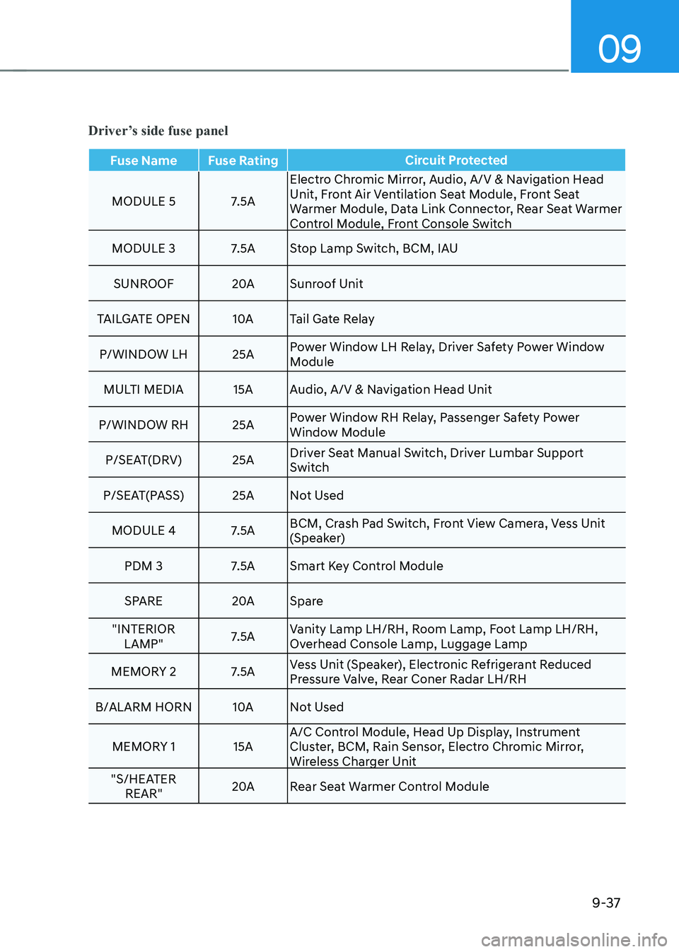
Driver’s side fuse panel
Fuse Name Fuse RatingCircuit Protected
MODULE 5 7.5AElectro Chromic Mirror, Audio, A/V & Navigation Head
Unit, Front Air Ventilation Seat Module, Front Seat
Warmer Module, Data Link Connector, Rear Seat Warmer
Control Module, Front Console Switch
MODULE 3 7.5A Stop Lamp Switch, BCM, IAU
SUNROOF 20ASunroof Unit
TAILGATE OpEN 10ATail Gate Relay
p/WINDOW LH 25A power Window LH Relay, Driver Safety power Window
Module
MULTI MEDIA 15A Audio, A/V & Navigation Head Unit
p/WINDOW RH 25A power Window RH Relay, passenger Safety power
Window Module
p/SEAT(DRV) 25A Driver Seat Manual Switch, Driver Lumbar Support
Switch
p/SEAT(pASS) 25A Not Used
MODULE 4 7.5A BCM, Crash pad Switch, Front View Camera, Vess Unit
(Speaker)
pDM 3 7.5A Smart Key Control Module
SpARE 20ASpare
"INTERIOR LAMp" 7.5AVanity Lamp LH/RH, Room Lamp, Foot Lamp LH/RH,
Overhead Console Lamp, Luggage Lamp
MEMORY 2 7.5A Vess Unit (Speaker), Electronic Refrigerant Reduced
pressure Valve, Rear Coner Radar LH/RH
B/ALARM HORN 10ANot Used
MEMORY 1 15A A/C Control Module, Head Up Display, Instrument
Cluster, BCM, Rain Sensor, Electro Chromic Mirror,
Wireless Charger Unit
"S/HEATER REAR" 20A
Rear Seat Warmer Control Module
Page 514 of 548
Maintenance
9-38
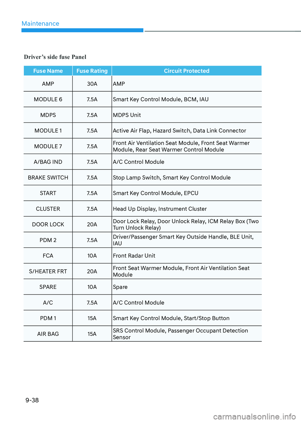
Fuse Name Fuse RatingCircuit Protected
AMp
30AAMp
MODULE 6 7.5A Smart Key Control Module, BCM, IAU MDpS 7.5A MDpS Unit
MODULE 1 7.5A Active Air Flap, Hazard Switch, Data Link Connector
MODULE 7 7.5A Front Air Ventilation Seat Module, Front Seat Warmer
Module, Rear Seat Warmer Control Module
A/BAG IND 7.5A A/C Control Module
BRAKE SWITCH 7.5A Stop Lamp Switch, Smart Key Control Module STA RT 7.5A Smart Key Control Module, EpCU
CLUSTER 7.5A Head Up Display, Instrument Cluster
DOOR LOCK 20ADoor Lock Relay, Door Unlock Relay, ICM Relay Box (Two
Turn Unlock Relay)
pDM 2 7.5A Driver/passenger Smart Key Outside Handle, BLE Unit,
IAU
FCA 10AFront Radar Unit
S/HEATER FRT 20AFront Seat Warmer Module, Front Air Ventilation Seat
Module
SpARE 10ASpare
A/C 7.5A A/C Control Module
pDM 1 15A Smart Key Control Module, Start/Stop Button
AIR BAG 15A SRS Control Module, passenger Occupant Detection Sensor
Driver’s side fuse Panel
Page 528 of 548
Maintenance
9-52
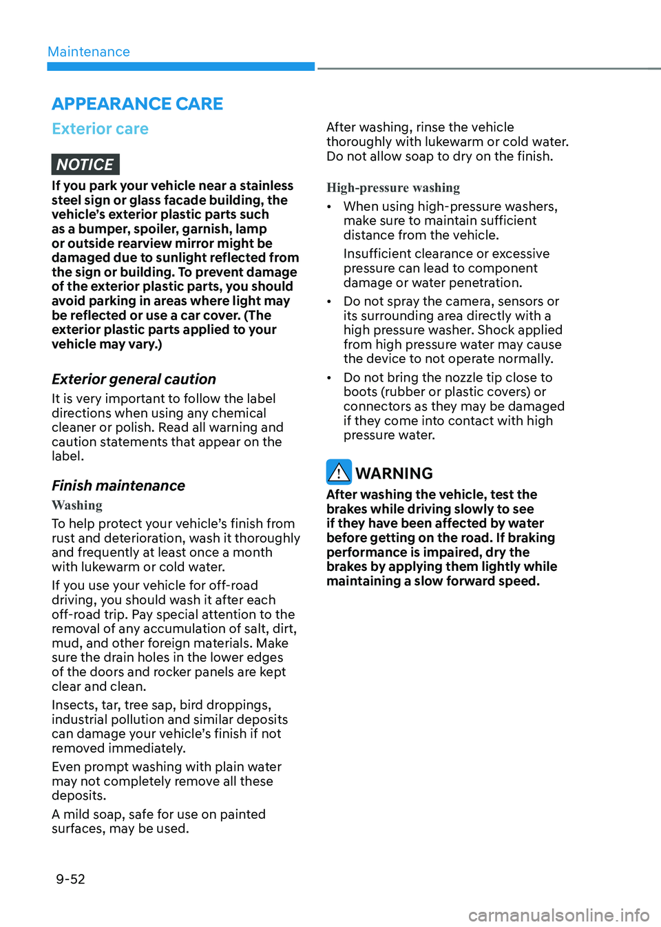
APPEARANCE CARE
Exterior care
NOTICE
If you park your vehicle near a stainless
steel sign or glass facade building, the
vehicle’s exterior plastic parts such
as a bumper, spoiler, garnish, lamp
or outside rearview mirror might be
damaged due to sunlight reflected from
the sign or building. To prevent damage
of the exterior plastic parts, you should
avoid parking in areas where light may
be reflected or use a car cover. (The
exterior plastic parts applied to your
vehicle may vary.)
Exterior general caution
It is very important to follow the label
directions when using any chemical
cleaner or polish. Read all warning and
caution statements that appear on the label.
Finish maintenance
Washing
To help protect your vehicle’s finish from
rust and deterioration, wash it thoroughly
and frequently at least once a month
with lukewarm or cold water.
If you use your vehicle for off-road
driving, you should wash it after each
off-road trip. pay special attention to the
removal of any accumulation of salt, dirt,
mud, and other foreign materials. Make
sure the drain holes in the lower edges
of the doors and rocker panels are kept clear and clean.
Insects, tar, tree sap, bird droppings,
industrial pollution and similar deposits
can damage your vehicle’s finish if not
removed immediately.
Even prompt washing with plain water
may not completely remove all these deposits.
A mild soap, safe for use on painted
surfaces, may be used. After washing, rinse the vehicle
thoroughly with lukewarm or cold water.
Do not allow soap to dry on the finish.
High-pressure washing
•
When using high-pressure washers,
make sure to maintain sufficient
distance from the vehicle.
Insufficient clearance or excessive
pressure can lead to component
damage or water penetration.
• Do not spray the camera, sensors or
its surrounding area directly with a
high pressure washer. Shock applied
from high pressure water may cause
the device to not operate normally.
• Do not bring the nozzle tip close to
boots (rubber or plastic covers) or
connectors as they may be damaged
if they come into contact with high
pressure water.
WARNING
After washing the vehicle, test the
brakes while driving slowly to see
if they have been affected by water
before getting on the road. If braking
performance is impaired, dry the
brakes by applying them lightly while
maintaining a slow forward speed.
Page 540 of 548
I
I-5
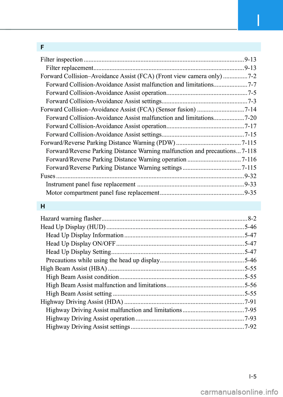
F Filter inspection ................................................................................................... 9-13
Filter replacement ............................................................................................. 9-13
Forward Collision–Avoidance Assist (FCA) (Front view camera only) ...............7-2
Forward Collision-Avoidance Assist malfunction and limitations..................... 7-7
Forward Collision-Avoidance Assist operation ..................................................7-5
Forward Collision-Avoidance Assist settings..................................................... 7-3
Forward Collision–Avoidance Assist (FCA) (Sensor fusion) .............................7-14
Forward Collision-Avoidance Assist malfunction and limitations................... 7-20
Forward Collision-Avoidance Assist operation ................................................7-17
Forward Collision-Avoidance Assist settings................................................... 7-15
Forward/Reverse Parking Distance Warning (PDW) ........................................7-115
Forward/Reverse Parking Distance Warning malfunction and precautions ...7-118
Forward/Reverse Parking Distance Warning operation .................................7-116
Forward/Reverse Parking Distance Warning settings ....................................7-115
Fuses .................................................................................................................... 9-32
Instrument panel fuse replacement .................................................................. 9-33
Motor compartment panel fuse replacement ....................................................9-35
H Hazard warning flasher .......................................................................................... 8-2
Head Up Display (HUD) ..................................................................................... 5-46
Head Up Display Information .......................................................................... 5-47
Head Up Display ON/OFF ............................................................................... 5-47
Head Up Display Setting .................................................................................. 5-47
Precautions while using the head up display ....................................................5-46
High Beam Assist (HBA) .................................................................................... 5-55
High Beam Assist condition ............................................................................. 5-55
High Beam Assist malfunction and limitations ................................................5-56
High Beam Assist setting ................................................................................. 5-55
Highway Driving Assist (HDA) .......................................................................... 7-91
Highway Driving Assist malfunction and limitations ......................................7-95
Highway Driving Assist operation ................................................................... 7-93
Highway Driving Assist settings ...................................................................... 7-92
Page 545 of 548
Index
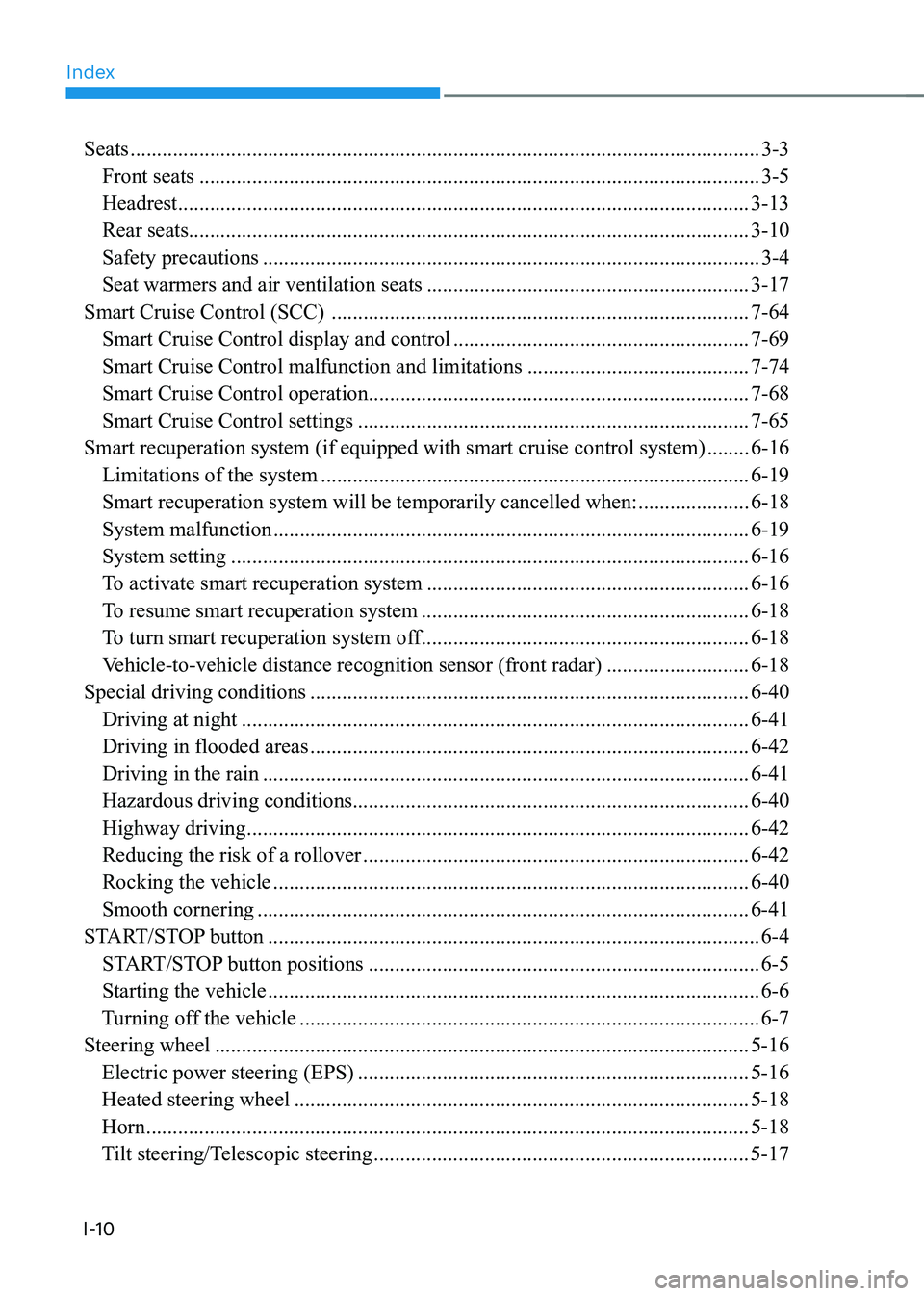
I-10Seats
....................................................................................................................... 3-3
Front seats .......................................................................................................... 3-5
Headrest ............................................................................................................ 3-13
Rear seats .......................................................................................................... 3-10
Safety precautions .............................................................................................. 3-4
Seat warmers and air ventilation seats .............................................................3-17
Smart Cruise Control (SCC) ............................................................................... 7-64
Smart Cruise Control display and control ........................................................7-69
Smart Cruise Control malfunction and limitations ..........................................7-74
Smart Cruise Control operation ........................................................................ 7-68
Smart Cruise Control settings .......................................................................... 7-65
Smart recuperation system (if equipped with smart cruise control system) ........6-16
Limitations of the system ................................................................................. 6-19
Smart recuperation system will be temporarily cancelled when: .....................6-18
System malfunction .......................................................................................... 6-19
System setting .................................................................................................. 6-16
To activate smart recuperation system .............................................................6-16
To resume smart recuperation system ..............................................................6-18
To turn smart recuperation system off ..............................................................6-18
Vehicle-to-vehicle distance recognition sensor (front radar) ...........................6-18
Special driving conditions ................................................................................... 6-40
Driving at night ................................................................................................ 6-41
Driving in flooded areas ................................................................................... 6-42
Driving in the rain ............................................................................................ 6-41
Hazardous driving conditions ........................................................................... 6-40
Highway driving ............................................................................................... 6-42
Reducing the risk of a rollover ......................................................................... 6-42
Rocking the vehicle .......................................................................................... 6-40
Smooth cornering ............................................................................................. 6-41
START/STOP button ............................................................................................. 6-4
START/STOP button positions .......................................................................... 6-5
Starting the vehicle ............................................................................................. 6-6
Turning off the vehicle ....................................................................................... 6-7
Steering wheel ..................................................................................................... 5-16
Electric power steering (EPS) .......................................................................... 5-16
Heated steering wheel ...................................................................................... 5-18
Horn .................................................................................................................. 5-18
Tilt steering/Telescopic steering ....................................................................... 5-17