Page 458 of 543

Emergency Situations8-14
Each wheel is equipped with a tire
pressure sensor mounted inside the tire
behind the valve stem (except for the
spare tire). You must use TPMS specific
wheels. It is recommended that you
always have your tires serviced by an
authorized HYUNDAI dealer.
You may not be able to identify a tire
with low pressure by simply looking at it.
Always use a good quality tire pressure
gauge to measure the tire’s inflation
pressure. Please note that a tire that is
hot (from being driven) will have a higher
pressure measurement than a tire that is
cold.
A cold tire means the vehicle has been
sitting for 3 hours and driven for less
than 1 mile (1.6 km) in that 3 hour period.
Allow the tire to cool before measuring
the inflation pressure. Always be sure
the tire is cold before inflating to the
recommended pressure.
WARNING
�[�� The TPMS cannot alert you to severe
and sudden tire damage caused by
external factors such as nails or road
debris.
�[�� If you feel any vehicle instability,
immediately take your foot off
the accelerator, apply the brakes
gradually with light force, and slowly
move to a safe position off the road.
WARNING
Tampering with, modifying, or disabling
the Tire Pressure Monitoring System
(TPMS) components may interfere
with the system’s ability to warn the
driver of low tire pressure conditions
and/or TPMS malfunctions. Tampering
with, modifying, or disabling the Tire
Pressure Monitoring System (TPMS)
components may void the warranty for
that portion of the vehicle.
Information
This device complies with Part 15 of the
FCC rules.
Operation is subject to the following three
conditions:
1. This device may not cause harmful
interference.
2. This device must accept any
interference received, including
interference that may cause undesired
operation.
3. Changes or modifications not expressly
approved by the party responsible
for compliance could void the user’s
authority to operate the equipment.
Page 466 of 543

Emergency Situations8-22
WARNING
If your vehicle is equipped with a
rollover sensor, place the ignition
switch in the LOCK/OFF or ACC position
when the vehicle is being towed.
The side impact and curtain air bag
may deploy if the sensor detects the
situation as a rollover.
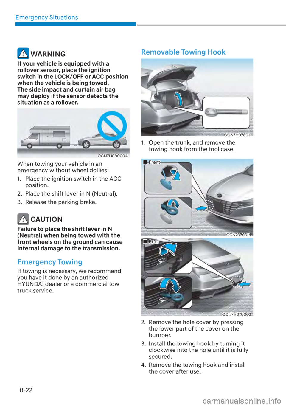
OCN7H080004
When towing your vehicle in an
emergency without wheel dollies:
1. Place the ignition switch in the ACC position.
2. Place the shift lever in N (Neutral).
3. Release the parking brake.
CAUTION
Failure to place the shift lever in N
(Neutral) when being towed with the
front wheels on the ground can cause
internal damage to the transmission.
Emergency Towing
If towing is necessary, we recommend
you have it done by an authorized
HYUNDAI dealer or a commercial tow
truck service.
Removable Towing Hook
OCN7H070011
1. Open the trunk, and remove the towing hook from the tool case.
���„Front
OCN7070014
���„Rear
OCN7H070003
2. Remove the hole cover by pressing the lower part of the cover on the
bumper.
3. Install the towing hook by turning it clockwise into the hole until it is fully
secured.
4. Remove the towing hook and install the cover after use.
Page 516 of 543

Maintenance9-48
Driver’s side fuse panel
Fuse Name Fuse Rating Circuit Protected
MEMORY1 10
AA/C Controller, Instrument Cluster,
A/C Control Module, Driver IMS Control Module
AIR BAG2 10A SRS Control Module
MODULE4 10AIBU, ATM Shift Lever Indicator, Front Console Switch,
ADAS Unit, Crash Pad Switch, LKA Unit, VESS Unit
MODULE7 7.5AIAU, ADAS Unit, Rear Seat Wamer Control Module,
Cooling Fan Motor
START 7.5ABurglar Alarm Relay, Transaxle Range Switch, IBU,
Ignition Switch
BATTERY
MANAGEMENT 10A BMS Control Module
CLUSTER 7.5A Instrument Cluster (IG1)
IBU2 7.5A IBU
A/C1 7.5AA/C Controller, A/C Control Module, PM Sensor,
E/R Junction Block (Blower Relay, PTC Heater1/2 Relay),
Electronic A/C Compressor
TRUNK 10A Trunk Relay
S/HEATER FRT 20AFront Ventilation Seat Control Module,
Front Seat Warmer Control Module
P/WINDOW LH 25A Power Window Main Switch
MULTIMEDIA 15A Audio, A/V & Navigation Head Unit
SPARE 1 (B+) 10A Not Used (Black Box)
FCA 10A Front Radar
MDPS 7.5A MDPS Unit
MODULE6 7.5A IBU
S/HEATER RR 20A Rear Seat Warmer Control Module
SAFETY P/
WINDOW DRV 25A Driver Safety Power Window Module
P/WINDOW RH 25APassenger Power Window Switch,
Power Window Main Switch
BRAKE SWITCH 10A IBU, Stop Lamp Switch
IBU1 15A IBU
Page 517 of 543

09
9-49
Driver’s side fuse panel
Fuse NameFuse Rating Circuit Protected
MODULE2 10
AA/V & Navigation Head Unit, AMP, ADAS Unit,
BMS Control Module, Power Outside Mirror Switch,
IBU, IAU, Audio, E/R Junction Block (Power Outlet Relay)
AIR BAG1 15APassenger Occupant Detection Sensor,
SRS Control Module
MODULE5 10AData Link Connector, Audio, ATM Shift Lever Indicator,
A/V & Navigation Head Unit, Wireless Charger, AMP,
A/C Control Module, Electro Chromic Mirror,
A/C Controller, Rear Seat Wamer Control Module,
Front Ventilation Seat Control Module, Front Seat
Wamer Control Module, Driver IMS Control Module
SPARE 2 (IG2) 10A Not Used (Black Box)
AMP 25A AMP
HEATED MIRROR 10A A/C Controller, Driver/Passenger Power Outside Mirror
DOOR LOCK 20A Door Lock/Unlock Switch, Two Turn Unlock Relay
IAU 10A IAU, BLE Unit, Driver/Passenger Door NFC Module
MODULE3 7.5A IAU, Stop Lamp Switch, Sport Mode Switch
A/BAG IND 7.5A Instrument Cluster, Overhead Console Lamp (MTS)
WASHER 15A Multifunction Switch
P/SEAT PASS 30A Not Used
P/SEAT DRV 30A Driver Power Seat Switch, Driver IMS Control Module
WIPER 10AIBU, ECM, Front Wiper Motor,
PCB Block (Front Wiper (LOW) Relay)
MODULE1 10AData Link Connector, Hazard Switch, Key Interlock,
Driver/Passenger Smart Key Outside Handle,
Sport Mode Switch
SUNROOF 20A Sunroof Motor
USB CHARGER 15A Front USB Charger, Console USB Charger
IG1 25A PCB Block (Fuse - IEB 4/ECU 3/TCU 2/EWP 3)
Page 521 of 543
09
9-53
Engine compartment fuse panel
Fuse NameFuse Rating Circuit Protected
WIPER 25A
Wiper Relay
HORN 15A Horn Relay
IGN COIL 20A Ignition Coil #1 ~ #4
ECU2 15A ECM
SENSOR3 10A E/R Junction Block (Fuel Pump Relay)
SENSOR2 10ACamshaft Position Sensor #1/#2 (Intake/Exhaust), Mass
Air Flow Sensor, ELCM, Oil Control Valve #1/#2 (Intake/
Exhaust),
Purge Control Solenoid Valve
ECU3 10A ECM, HPCU, Clutch Actuator
SENSOR1 15A Oxygen Sensor (Up/Down)
IEB 4 10A IDB Unit, Multipurpose Check Connector
EWP 3 10A Auxiliary Electric Water Pump
ECU1 20A ECM
TCU2 15A Transaxle Range Switch, TCM
Page 531 of 543

09
9-63
APPEARANCE CARE
Exterior Care
Exterior general caution
It is very important to follow the label
directions when using any chemical
cleaner or polish. Read all warning and
caution statements that appear on the
label.
High-pressure washing
�[��When using high-pressure washers,
make sure to maintain sufficient
distance from the vehicle. Insufficient
clearance or excessive pressure can
lead to component damage or water
penetration.
�[�� Do not spray the camera, sensors or
its surrounding area directly with a
high pressure washer. Shock applied
from high pressure water may cause
the device to not operate normally.
�[�� Do not bring the nozzle tip close to
boots (rubber or plastic covers) or
connectors as they may be damaged
if they come into contact with high
pressure water.
�[�� Do not use any high-pressure nozzles,
which induce either one-direct water
stream or water swirling.
Protecting your vehicle’s finish
Washing
To help protect your vehicle’s finish from
rus
t and deterioration, wash it thoroughly
and frequently at least once a month
with lukewarm or cold water.
If you use your vehicle for off-road
driving, you should wash it after each
off-road trip. Pay special attention to the
removal of any accumulation of salt, dirt,
mud, and other foreign materials. Make
sure the drain holes in the lower edges
of the doors and rocker panels are kept
clear and clean.
Insects, tar, tree sap, bird droppings,
industrial pollution and similar deposits
can damage your vehicle’s finish if not
removed immediately.
Even prompt washing with plain water
may not completely remove all these
deposits. A mild soap, safe for use on
painted surfaces, should be used.
After washing, rinse the vehicle
thoroughly with lukewarm or cold water.
Do not allow soap to dry on the finish.
High-pressure washing
�[�� When using high-pr
essure washers,
make sure to maintain sufficient
distance from the vehicle. Insufficient
clearance or excessive pressure can
lead to component damage or water
penetration.
�[�� Do not spray the camera, sensors or
its surrounding area directly with a
high pressure washer. Shock applied
from high pressure water may cause
the device to not operate normally.
�[�� Do not bring the nozzle tip close to
boots (rubber or plastic covers) or
connectors as they may be damaged
if they come into contact with high
pressure water.