2023 FORD F650/750 wheel
[x] Cancel search: wheelPage 196 of 378
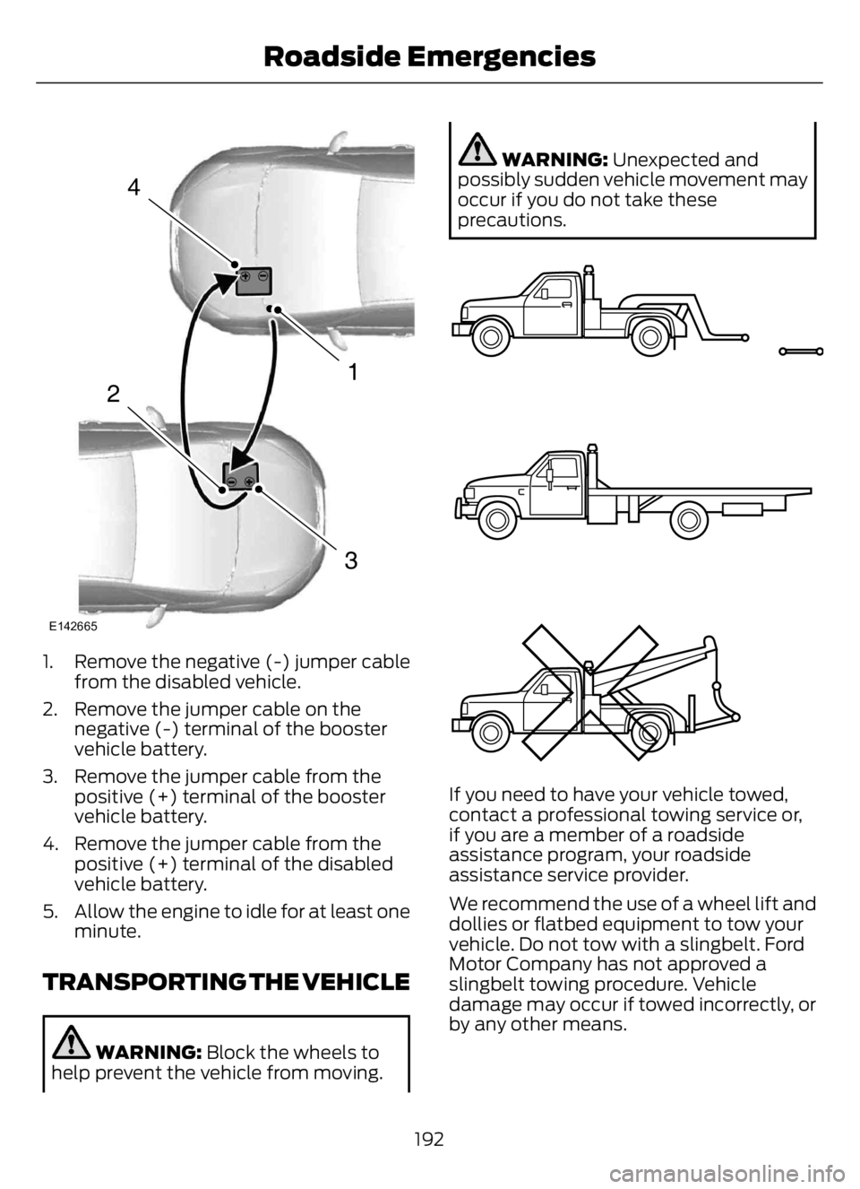
4
1
3
2
E142665
1. Remove the negative (-) jumper cable
from the disabled vehicle.
2. Remove the jumper cable on the
negative (-) terminal of the booster
vehicle battery.
3. Remove the jumper cable from the
positive (+) terminal of the booster
vehicle battery.
4. Remove the jumper cable from the
positive (+) terminal of the disabled
vehicle battery.
5. Allow the engine to idle for at least one
minute.
TRANSPORTING THE VEHICLE
WARNING: Block the wheels to
help prevent the vehicle from moving.
WARNING: Unexpected and
possibly sudden vehicle movement may
occur if you do not take these
precautions.
E143886
If you need to have your vehicle towed,
contact a professional towing service or,
if you are a member of a roadside
assistance program, your roadside
assistance service provider.
We recommend the use of a wheel lift and
dollies or flatbed equipment to tow your
vehicle. Do not tow with a slingbelt. Ford
Motor Company has not approved a
slingbelt towing procedure. Vehicle
damage may occur if towed incorrectly, or
by any other means.
192
Roadside Emergencies
Page 197 of 378

Ford Motor Company produces a towing
manual for all authorized tow truck
operators. Have your tow truck operator
refer to this manual for proper hook-up
and towing procedures for your vehicle.
It is acceptable to have your two-wheel
drive vehicle towed with the front wheels
on the ground (without dollies) and the
rear wheels off the ground.
TOWING POINTS
WARNING: Using recovery hooks
is dangerous and should only be done by
a person familiar with proper vehicle
recovery safety practices. Improper use
of recovery hooks may cause hook failure
or separation from the vehicle and could
result in serious injury or death.
WARNING: Always slowly remove
the slack from the recovery strap prior
to pulling. Failure to do so can introduce
significantly higher loads which can
cause the recovery hooks to break off, or
the recovery strap to fail which can cause
serious injury or death.
WARNING: Never link two straps
together with a clevis pin. These heavy
metal objects could become projectiles
if the strap breaks and can cause serious
injury or death.
Your vehicle comes equipped with
frame-mounted front recovery hooks.
These hooks should never have a load
applied to them greater than the gross
vehicle weight rating of your vehicle.Before using recovery hooks:
• Make sure all attaching points are
secure and capable of withstanding
the applied load.
• Never use chains, cables or tow straps
with metal hook ends.
• Only use recovery straps that have a
minimum breaking strength two to
three times the gross vehicle weight of
the stuck vehicle.
• Make sure the recovery strap is in good
condition and free of visible cuts, tears
or damage.
• Use a damper device such as a tarp,
heavy blanket or piece of carpet
draped over the recovery strap to help
absorb the energy in the event the
strap breaks.
• Make sure the stuck vehicle is not
loaded heavier than its gross vehicle
weight rating specified on the
certification label.
• Always align the tow vehicle and stuck
vehicle in a straight line (within 10
degrees).
• Keep bystanders to the sides of the
vehicle, at a distance of at least twice
the length of the recovery strap. This
helps avoid injury from the hazard of a
recovery hook or strap breaking, or a
vehicle lurching into their path.
193
Roadside Emergencies
Page 214 of 378
VEHICLE INSPECTION
INFORMATION
To make sure your vehicle is ready to
operate, conduct a pre-trip inspection at
the beginning of each work period. Follow
the steps listed in this section to verify a
proper vehicle inspection procedure.
WARNING: Exercise great caution
when working on a vehicle equipped with
an automatic fan clutch. The fan starts
in motion only after the engine coolant
reaches a predetermined temperature
or the refrigerant pressure (if equipped
with air conditioning) reaches a
predetermined setting. The fan starts at
this point with no advance warning.
Never reach near, or permit objects to
protrude into, the fan blade radius while
the engine is running as this could result
in vehicle damage, personal injury or
death.
WARNING: Do not operate the
vehicle if any suspension conditions
listed in the following charts are evident.
Loss of steering or suspension could
result in property damage, personal injury
or death.
WARNING: If a wheel must be
changed, obtain expert tire service help.
Mounting and un-mounting of tires
should only be performed by a qualified
technician using necessary safety
procedures and equipment, otherwise
the result could be property damage,
personal injury or death.
Note:Always make sure you apply the
parking brake before starting the engine.
Engine compartment (with engine off)
Use the dipstick to verify the oil level is in the proper operating
range. See Engine Oil Dipstick (page 224). Engine oil
Look through the plastic reservoir and verify the coolant level
is within the proper operating range. Do not remove the
pressure cap until the coolant has cooled. See Engine
Coolant Check (page 238). Engine coolant
Verify that the fluid level is in the proper operating range. See
Power Steering Fluid Check (page 245). Power steering fluid
Remove the master cylinder caps and inspect the fluid level.
See Brake Fluid Check (page 244). Brake fluid
210
Vehicle Inspection Guide
Page 215 of 378
Engine compartment (with engine off)
Inspect for glazing, fraying or cracking. There should be no
more than 5-7 cracks per rib, per 1 in (2.5 cm) Belts (fan, alternator,
water pump and air
conditioning
compressor)
Inspect for signs of fluid puddles or dripping fluid on the
ground under the engine, or the underside of the engine. Fluid leaks
Inspect for debris that may have collected on the HVAC air
inlet grille or inside the exterior module as this may reduce
system performance. HVAC air inlet
Engine starting (with parking brake applied)
Before entering the cab, verify that the vehicle is equipped
with spare electrical fuses (if used), three red reflective
triangles, a properly charged and rated fire extinguisher and
wheel chocks. Safety and emergency
equipment
Walk around the vehicle and verify all steps and grab handles,
inside and out (as well as behind), are tight and clean. Use
extreme caution and a three-point stance at all times.
Inspect door latches for proper closing, latching and locking.
Set the parking brake. Make sure the gearshift lever is in
neutral (N) or park (P) (if equipped with a park position). Starting the engine
Diesel engine: Turn the key to the on position. Turn the key
to start when the wait to start indicator light in the instrument
cluster turns off.
Gasoline engine: Turn the key to start, and then release it
as soon as the engine starts.
Verify pressure builds to normal operating range. Engine oil pressure
A tone indicating low air pressure should sound immediately
after the engine starts but before the compressor has built-
up pressure. The tone should stop when the air pressure
reaches 70 psi (483 kPa). Let the air pressure build to
governed cutout pressure, which should occur between
115–130 psi (793–896 kPa). Low air pressure warning
tone (if equipped with an
air compressor)
Press the accelerator and verify that it operates smoothly,
without any binding or irregular feel. Release the pedal and
verify the engine returns to idle speed immediately. Accelerator
211
Vehicle Inspection Guide
Page 216 of 378

Engine starting (with parking brake applied)
Check the gauge (diesel engine) or indicator light (gasoline
engine) to verify the alternator is charging. Voltmeter
Inspect for excessive free play in the steering linkages. The
steering wheel should have less than 2 in (5 cm) of free play
at its rim. Steering linkage free play
Verify the parking brake holds the vehicle by gently trying to
pull forward with the parking brake applied. Parking brake
Verify operation using the following procedure. Chock the
wheels, if necessary. Push in the parking brake and, on
tractors, push in the tractor parking brake knob: Air brakes
1. Verify the air compressor or governor cutout pressure is
approximately 120 psi (827 kPa).
2. Turn off the engine, and then turn the key back to the on
position (without starting the engine).
3. Without the brake pedal applied, note the air pressure drop
for one minute. It should be less than 2 psi (14 kPa) for single
vehicles and 3 psi (21 kPa) for combination vehicles.
4. Press and hold the brake pedal with 90 psi (621 kPa) or
more. Make sure there is no more than a 3 psi (21 kPa) per
minute leak for single vehicles and a 4 psi (28 kPa) minute
leak for combination vehicles.
5. Pump the brake pedal to deplete the system of air pressure.
The warning light and tone should turn on at 57 psi (393 kPa).
6. Pump the brake pedal and make sure the parking brake
and trailer parking brake knobs pop out at 20 psi (138 kPa)
or higher.
Verify that the fluid level is in the proper operating range. See
Automatic Transmission Fluid Check (page 242). Automatic transmission
fluid
Front of vehicle
Verify all exterior lights illuminate and are clean. Lights
Check headlights function on high and low beam.
Verify reflectors are clean, unbroken and of proper color (red
on rear, amber elsewhere).
212
Vehicle Inspection Guide
Page 218 of 378
Front brakes
Inspect for cracked, worn or frayed hoses, and that all coup-
lings are secure. Hoses
Verify that there are no cracks or dents, and that the cham-
bers are securely mounted. Brake chambers
Inspect for broken, loose or missing parts. Slack adjusters
Note: The angle between the push rod and adjuster arm
should be approximately 90 degrees when the brakes are
applied. When pulled by hand, the push rod should not move
more than approximately 1 in (2.5 cm).
Verify that there are no cracks, dents, holes, and no loose or
missing bolts and that the brake linings are not worn,
dangerously thin or contaminated by lubricant. Drums
Front wheels
Inspect for damaged or bent rims. They should not have
welding repairs, and there should be no rust trails, which
indicate it is loose on the wheel. Rims
Verify all lug nuts are present and not loose (look for rust
trails around the lug nuts). There should be no cracks radiating
from the lug bolt holes or distortion of the bolt holes. Lug nuts
Inspect wheel hub oil seal for leaks and, if sight glass if
present, verify the oil level is adequate. Hub oil seals
Inspect for proper lubrication level if the hubcap has a trans-
parent window. If the hubcap does not have a transparent
window, remove the rubber fill-plug and inspect for proper
level. Oil-lubricated front
wheel bearings
Fuel area
Verify the tank(s) and cap(s) are secure and that there are
no leaks from the tank(s). Fuel tank(s)
Inspect for leaks from the tank(s). Leaks
214
Vehicle Inspection Guide
Page 220 of 378
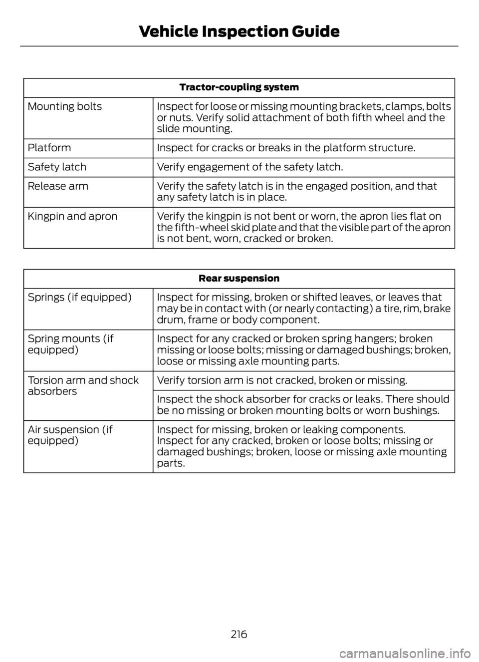
Tractor-coupling system
Inspect for loose or missing mounting brackets, clamps, bolts
or nuts. Verify solid attachment of both fifth wheel and the
slide mounting. Mounting bolts
Inspect for cracks or breaks in the platform structure. Platform
Verify engagement of the safety latch. Safety latch
Verify the safety latch is in the engaged position, and that
any safety latch is in place. Release arm
Verify the kingpin is not bent or worn, the apron lies flat on
the fifth-wheel skid plate and that the visible part of the apron
is not bent, worn, cracked or broken. Kingpin and apron
Rear suspension
Inspect for missing, broken or shifted leaves, or leaves that
may be in contact with (or nearly contacting) a tire, rim, brake
drum, frame or body component. Springs (if equipped)
Inspect for any cracked or broken spring hangers; broken
missing or loose bolts; missing or damaged bushings; broken,
loose or missing axle mounting parts. Spring mounts (if
equipped)
Verify torsion arm is not cracked, broken or missing. Torsion arm and shock
absorbers
Inspect the shock absorber for cracks or leaks. There should
be no missing or broken mounting bolts or worn bushings.
Inspect for missing, broken or leaking components. Air suspension (if
equipped) Inspect for any cracked, broken or loose bolts; missing or
damaged bushings; broken, loose or missing axle mounting
parts.
216
Vehicle Inspection Guide
Page 221 of 378
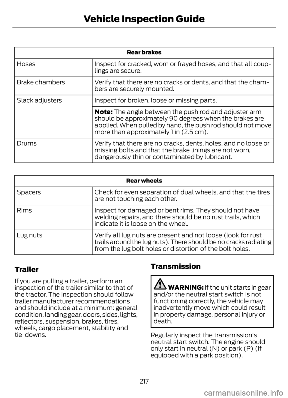
Rear brakes
Inspect for cracked, worn or frayed hoses, and that all coup-
lings are secure. Hoses
Verify that there are no cracks or dents, and that the cham-
bers are securely mounted. Brake chambers
Inspect for broken, loose or missing parts. Slack adjusters
Note: The angle between the push rod and adjuster arm
should be approximately 90 degrees when the brakes are
applied. When pulled by hand, the push rod should not move
more than approximately 1 in (2.5 cm).
Verify that there are no cracks, dents, holes, and no loose or
missing bolts and that the brake linings are not worn,
dangerously thin or contaminated by lubricant. Drums
Rear wheels
Check for even separation of dual wheels, and that the tires
are not touching each other. Spacers
Inspect for damaged or bent rims. They should not have
welding repairs, and there should be no rust trails, which
indicate it is loose on the wheel. Rims
Verify all lug nuts are present and not loose (look for rust
trails around the lug nuts). There should be no cracks radiating
from the lug bolt holes or distortion of the bolt holes. Lug nuts
Trailer
If you are pulling a trailer, perform an
inspection of the trailer similar to that of
the tractor. The inspection should follow
trailer manufacturer recommendations
and should include at a minimum: general
condition, landing gear, doors, sides, lights,
reflectors, suspension, brakes, tires,
wheels, cargo placement, stability and
tie-downs.
Transmission
WARNING: If the unit starts in gear
and/or the neutral start switch is not
functioning correctly, the vehicle may
inadvertently move which could result
in property damage, personal injury or
death.
Regularly inspect the transmission's
neutral start switch. The engine should
only start in neutral (N) or park (P) (if
equipped with a park position).
217
Vehicle Inspection Guide