2023 FORD F650/750 battery
[x] Cancel search: batteryPage 122 of 378

Your vehicle may not pass the I/M test if
the service engine soon indicator is on or
not working properly (bulb is burned out),
or if the OBD-II system has determined
that some of the emission control systems
have not been properly checked. In this
case, the vehicle is not ready for I/M
testing.
If the vehicle’s engine or transmission has
just been serviced, or the battery has
recently run down or been replaced, the
OBD-II system may indicate that the
vehicle is not ready for I/M testing. To
determine if the vehicle is ready for I/M
testing, turn the ignition key to the on
position for 15 seconds without cranking
the engine. If the service engine soon
indicator blinks eight times, it means that
the vehicle is not ready for I/M testing; if
the service engine soon indicator stays on
solid, it means that your vehicle is ready
for I/M testing.
The OBD-II system checks the emission
control system during normal driving. A
complete check may take several days.
If the vehicle is not ready for I/M testing,
you can perform the following driving cycle
consisting of mixed city and highway
driving:
1. 15 minutes of steady driving on an
expressway or highway followed by 20
minutes of stop-and-go driving with at
least four 30-second idle periods.
2. Allow your vehicle to sit for at least
eight hours with the ignition off. Then,
start the vehicle and complete the
above driving cycle. The vehicle must
warm up to its normal operating
temperature. Once started, do not turn
off the vehicle until the above driving
cycle is complete.
If the vehicle is still not ready for I/M
testing, you need to repeat the above
driving cycle.SELECTIVE CATALYTIC
REDUCTANT SYSTEM - DIESEL
Your vehicle may have a selective catalytic
reduction system. This system helps
reduce emission levels of oxides of
nitrogen from the exhaust system. The
system automatically injects diesel
exhaust fluid into the exhaust system to
enable correct selective catalytic reduction
system function.
Note:Selective catalytic reduction systems
are not fitted to vehicles in markets where
only high-sulfur diesel fuel is available.
Diesel Exhaust Fluid Level
In order for the system to operate correctly
you must maintain the diesel exhaust fluid
level.
The system has a sensor to monitor fluid
level and quality/concentration. A warning
message appears in the information
display when the diesel exhaust fluid level
is low. If a warning message appears, refill
the diesel exhaust fluid tank as soon as
possible. See Information Messages
(page 74).
Filling the Diesel Exhaust Fluid
Tank
WARNING: Keep diesel exhaust
fluid out of reach of children. Avoid
contact with skin, eyes or clothing. In
case of contact with your eyes, flush
immediately with water and get prompt
medical attention. In case of contact
with your skin, clean immediately with
soap and water. If you swallow any
diesel exhaust fluid, drink plenty of
water, call a physician immediately.
118
Engine Emission Control
Page 192 of 378

ROADSIDE ASSISTANCE
Vehicles Sold in the United States:
Getting Roadside Assistance
To fully assist you should you have a
vehicle concern, Ford Motor Company
offers a complimentary roadside
assistance program. This program is
separate from the New Vehicle Limited
Warranty.
The service is available:
• 24 hours a day, seven days a week.
• For the coverage period supplied with
your vehicle.
Roadside Assistance covers:
• A flat tire change with a good spare
(except vehicles supplied with a tire
inflation kit).
• Battery jump start.
• Lock-out assistance (key replacement
cost is the customer's responsibility).
• Fuel delivery — independent service
contractors, if not prohibited by state,
local or municipal law, shall deliver up
to 2 gal (8 L) of gasoline or 5 gal (20 L)
of diesel fuel to a disabled vehicle.
Roadside Assistance limits fuel delivery
service to two no-charge occurrences
within a 12-month period.
• Winch out — available within 100 ft
(30 m) of a paved or county
maintained road, no recoveries.• Towing — independent service
contractors, if not prohibited by state,
local or municipal law, shall tow Ford
eligible vehicles to an authorized dealer
within 35 mi (56 km) of the
disablement location or to the nearest
authorized dealer. If a member
requests a tow to an authorized dealer
that is more than 35 mi (56 km) from
the disablement location, the member
shall be responsible for any mileage
costs in excess of 35 mi (56 km).
• Roadside Assistance includes up to
$200 for a towed trailer if the disabled
eligible vehicle requires service at the
nearest authorized dealer. If the towing
vehicle is operational but the trailer is
not, then the trailer does not qualify for
any roadside services.
Vehicles Sold in the United States:
Using Roadside Assistance
Complete the roadside assistance
identification card and place it in your
wallet for quick reference. This card is in
the Owner's Manual kit.
United States vehicle customers who
require Roadside Assistance, call
1-800-241-3673.
If you need to arrange roadside assistance
for yourself, Ford Motor Company
reimburses a reasonable amount for
towing to the nearest dealership within
35 mi (56 km). To obtain reimbursement
information, United States vehicle
customers call 1-800-241-3673.
Customers need to submit their original
receipts.
188
Roadside Emergencies
Page 193 of 378

Vehicles Sold in Canada: Getting
Roadside Assistance
To fully assist you should you have a
vehicle concern, Ford Motor Company of
Canada, Limited offers a complimentary
roadside assistance program. This program
is eligible within Canada or the continental
United States.
The service is available 24 hours a day,
seven days a week.
This program is separate from the New
Vehicle Limited Warranty, but the coverage
is concurrent with the powertrain coverage
period of your vehicle. Canadian roadside
coverage and benefits may differ from the
U.S. coverage.
If you require more information, please call
us in Canada at 1-800-665-2006, or visit
our website at www.ford.ca.
HAZARD FLASHERS
Note:If used when the vehicle is not
running, the battery loses charge. As a result,
there may be insufficient power to restart
your vehicle.
E304635E304635
The hazard flasher control is located on
the instrument panel. Use it when your
vehicle is creating a safety hazard for other
motorists.• Press the flasher control and all front
and rear direction indicators flash.
• Press the flasher control again to
switch them off.
FUEL SHUTOFF
WARNING: If your vehicle has been
involved in a crash, have the fuel system
checked. Failure to follow this instruction
could result in fire, personal injury or
death.
Note: When you try to restart your vehicle
after a fuel shutoff, your vehicle makes sure
that various systems are safe to restart.
Once your vehicle determines that the
systems are safe, your vehicle allows you to
restart.
Note:In the event that your vehicle does
not restart after your third attempt, contact
a qualified technician.
The fuel pump shutoff stops the flow of
fuel to the engine in the event of a
moderate to severe crash. Not every
impact causes a shutoff.
Should your vehicle shut off after a crash,
you may restart your vehicle.
If your vehicle has a key system:
1. Turn key to the off position.
2. Turn key to the start position.
3. Turn key to the off position.
4. Turn key to the on position.
5. The fuel pump is now re-enabled.
189
Roadside Emergencies
Page 194 of 378

JUMP STARTING THE VEHICLE
WARNING: Batteries normally
produce explosive gases which can
cause personal injury. Therefore, do not
allow flames, sparks or lighted
substances to come near the battery.
When working near the battery, always
shield your face and protect your eyes.
Always provide correct ventilation.
WARNING: Keep batteries out of
reach of children. Batteries contain
sulfuric acid. Avoid contact with skin,
eyes or clothing. Shield your eyes when
working near the battery to protect
against possible splashing of acid
solution. In case of acid contact with skin
or eyes, flush immediately with water for
a minimum of 15 minutes and get prompt
medical attention. If acid is swallowed,
call a physician immediately.
WARNING: Use only adequately
sized cables with insulated clamps.
Preparing Your Vehicle
Do not attempt to push-start your
automatic transmission vehicle.
Note:Attempting to push-start a vehicle
with an automatic transmission may cause
transmission damage.
Note:Use only a 12-volt supply to start your
vehicle.
Note:Do not disconnect the battery of the
disabled vehicle as this could damage the
vehicle electrical system.
Park the booster vehicle close to the hood
of the disabled vehicle, making sure the
two vehicles do not touch.
Connecting the Jumper Cables
WARNING: Do not attach the
cables to fuel lines, engine rocker covers,
the intake manifold or electrical
components as grounding points. Stay
clear of moving parts. To avoid reverse
polarity connections, make sure that you
correctly identify the positive (+) and
negative (-) terminals on both the
disabled and booster vehicles before
connecting the cables.
WARNING: Do not attach the end
of the positive cable to the studs or
L-shaped eyelet located above the
positive (+) terminal of your vehicle’s
battery. High current may flow through
and cause damage to the fuses.
WARNING: Do not connect the end
of the second cable to the negative (-)
terminal of the battery to be jumped. A
spark may cause an explosion of the
gases that surround the battery.
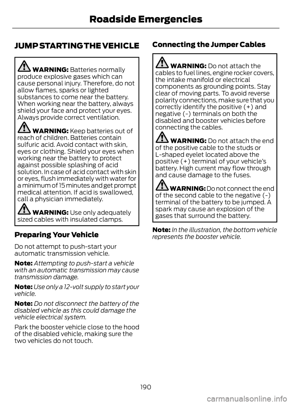
Note:In the illustration, the bottom vehicle
represents the booster vehicle.
190
Roadside Emergencies
Page 195 of 378

4
2
1
3
E142664
1. Connect the positive (+) jumper cable
to the positive (+) terminal of the
discharged battery.
2. Connect the other end of the positive
(+) cable to the positive (+) terminal
of the booster vehicle battery.
3. Connect the negative (-) cable to the
negative (-) terminal of the booster
vehicle battery.
4. Make the final connection of the
negative (-) cable to an exposed metal
part of the stalled vehicle's engine,
away from the battery and the fuel
injection system, or connect the
negative (-) cable to a ground
connection point if available.
E213266
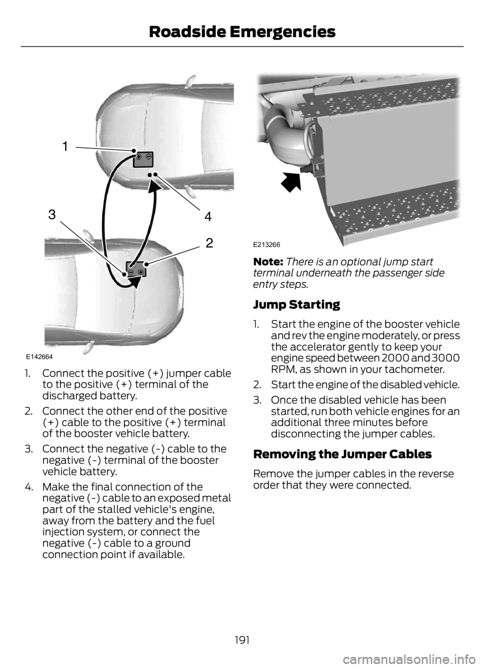
Note:There is an optional jump start
terminal underneath the passenger side
entry steps.
Jump Starting
1. Start the engine of the booster vehicle
and rev the engine moderately, or press
the accelerator gently to keep your
engine speed between 2000 and 3000
RPM, as shown in your tachometer.
2. Start the engine of the disabled vehicle.
3. Once the disabled vehicle has been
started, run both vehicle engines for an
additional three minutes before
disconnecting the jumper cables.
Removing the Jumper Cables
Remove the jumper cables in the reverse
order that they were connected.
191
Roadside Emergencies
Page 196 of 378

4
1
3
2
E142665
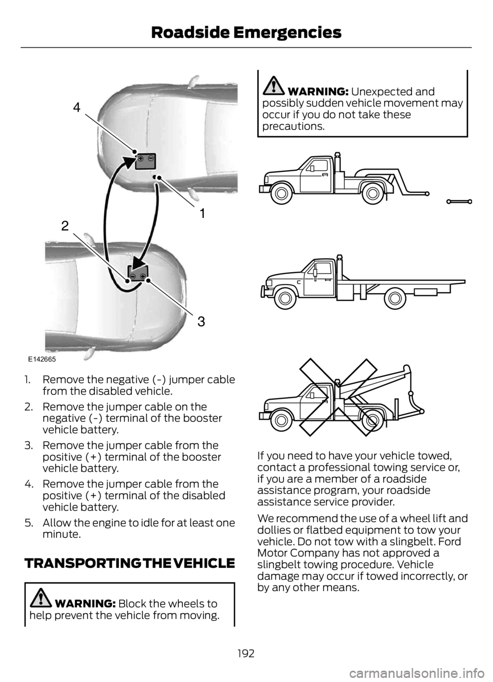
1. Remove the negative (-) jumper cable
from the disabled vehicle.
2. Remove the jumper cable on the
negative (-) terminal of the booster
vehicle battery.
3. Remove the jumper cable from the
positive (+) terminal of the booster
vehicle battery.
4. Remove the jumper cable from the
positive (+) terminal of the disabled
vehicle battery.
5. Allow the engine to idle for at least one
minute.
TRANSPORTING THE VEHICLE
WARNING: Block the wheels to
help prevent the vehicle from moving.
WARNING: Unexpected and
possibly sudden vehicle movement may
occur if you do not take these
precautions.
E143886
If you need to have your vehicle towed,
contact a professional towing service or,
if you are a member of a roadside
assistance program, your roadside
assistance service provider.
We recommend the use of a wheel lift and
dollies or flatbed equipment to tow your
vehicle. Do not tow with a slingbelt. Ford
Motor Company has not approved a
slingbelt towing procedure. Vehicle
damage may occur if towed incorrectly, or
by any other means.
192
Roadside Emergencies
Page 204 of 378

FUSE SPECIFICATION CHART
Engine Compartment Fuse Box
WARNING: Always disconnect the
battery before servicing high current
fuses.
WARNING: To reduce risk of
electrical shock, always replace the
cover to the power distribution box
before reconnecting the battery or
refilling fluid reservoirs.The engine compartment fuse box is in the
engine compartment. It has high-current
fuses that protect your vehicle's main
electrical systems from overloads.
If you disconnect and reconnect the
battery, you need to reset some features.
See Changing the 12V Battery (page 246).
Replace fuses with the same type and
rating. See Changing a Fuse (page 208).
E251921
Protected Component Rating Item
Horn. 20 A 1
Blower motor. 40 A 2
200
Fuses
Page 206 of 378

Protected Component Rating Item
Body control module run
power 1 bus. 50 A 25
Not used. — 26
Upfitter battery feed. 20 A 27
Not used. — 28
Alternator 1 A-Line. 10 A 29
Not used. — 30
Hydromax pump. 60 A 31
Powertrain control module. 20 A 32
Canister vent solenoid (gas). 20 A 33
Canister purge solenoid
(gas).
Variable cam timing actu-
ator 11 (gas).
Heated exhaust gas oxygen
sensor (gas).
Urea tank power (diesel).
Exhaust gas recirculation
cool bypass valve (diesel).
A/C clutch relay. 10 A 34
Customer access vehicle
power 3 feed.
Variable oil pump (diesel).
Cooling fan (diesel).
Fan clutch (gas).
Exhaust brake switch.
Variable oil pressure control
(gas)
Coil on plug (gas) 20 A 35
Urea tank (diesel).
Glow plug controller
(diesel).
Nitrogen oxide sensor
control module (diesel).
Particulate matter sensor
(diesel).
Fuel volume control value
(diesel). 10 A 36
202
Fuses