2023 FORD EXPLORER height
[x] Cancel search: heightPage 47 of 573

Seatbelt fastened.A
Seatbelt not fastened.B
Seatbelt recently unfastened.C
FaultD
Deactivating and Activating theBelt-Minder Feature - Front outermostseats only
WARNING: While the systemallows you to deactivate it, this systemis designed to improve your chances ofbeing safely belted and surviving anaccident. We recommend you leave thesystem activated for yourself and otherswho may use the vehicle.
Note:The driver and front passengerwarnings switch on and off independently.When you perform this procedure for oneseating position, do not buckle the otherposition as this terminates the process.
Read Steps 1 - 4 before starting theprocedure.
Make sure that:
•You set the parking brake.
•The transmission is in park (P).
•The ignition is off.
•You close all vehicle doors.
•You unbuckle the driver and frontpassenger seatbelts.
1.Switch the ignition on. Do not start theengine.
2.Wait until the seatbelt warning lampturns off (about one minute). AfterStep 2, wait an additional five secondsbefore proceeding with Step 3. Onceyou start Step 3, you must completethe procedure within 60 seconds.
3.For the seating position you areswitching off, buckle then unbuckle theseatbelt three times at a moderatespeed, ending in the unbuckled state.After Step 3, the seatbelt warning lampturns on.
4.When the seatbelt warning lamp is on,buckle then unbuckle the seatbelt.After Step 4, the seatbelt warning lampflashes for confirmation.
•This switches the feature off if it iscurrently on.
•This switches the feature on if it iscurrently off.
CHILD RESTRAINT AND
SEATBELT MAINTENANCE
Inspect the vehicle seatbelts and childsafety seat systems periodically to makesure they work properly and are notdamaged. Inspect the vehicle and childrestraint seatbelts to make sure there areno nicks, tears or cuts. Replace ifnecessary. All vehicle seatbelt assemblies,including retractors, buckles, front seatbeltbuckle assemblies, buckle supportassemblies (slide bar-if equipped),shoulder belt height adjusters (ifequipped), shoulder belt guide on seatbackrest (if equipped), child safety seatLATCH and tether anchors, and attachinghardware, should be inspected after acrash. Read the child restraintmanufacturer's instructions for additionalinspection and maintenance informationspecific to the child restraint.
43
2023 Explorer (CTW) Canada/United States of America, enUSA, Edition date: 202209, First-PrintingSeatbeltsE274703
Page 79 of 573

*This method only works for vehicles withthe hands-free liftgate feature.
Setting the Liftgate Open Height
1.Open the liftgate.
2.Stop the liftgate movement by pressingthe control button on the liftgate whenit reaches the desired height.
Note:Once the liftgate has stoppedmoving, you can also manually move it tothe desired height.
3.Press and hold the liftgate controlbutton on the liftgate until you hear atone, indicating programming iscomplete.
Note:You can only use the liftgate controlbutton to program the height.
Note:You cannot program the height if theliftgate position is too low.
The new open liftgate height is recalledwhen the power liftgate is opened. Tochange the programmed height, repeat theabove procedure. Once you open thepower liftgate, you can manually move itto a different height.
Note:The system recalls the newprogrammed height until you reprogram it,even if you disconnect the battery.
When operating the power liftgate afteryou have programmed a lower height thanfully open, you can fully open the liftgateby manually pushing it upward to themaximum open position.
Obstacle Detection
Note:Entering your vehicle while theliftgate is closing can cause your vehicle tobounce and activate obstacle detection. Toprevent this, let the power liftgate closecompletely before you enter your vehicle.Before driving off, check the instrumentcluster for a liftgate or door ajar message orwarning indicator. Failure to do this couldresult in unintentionally leaving the liftgateopen while driving.
When Closing
The system stops when it detects anobstacle. A tone sounds and the systemreverses to open. Once you remove theobstacle, you can power close the liftgate.
When Opening
The system stops when it detects anobstacle and a tone sounds. Once youremove the obstacle, you can continue tooperate the liftgate.
Switching the Power Liftgate Onor Off
You can switch the power liftgate on or offthrough the vehicle settings on yourtouchscreen.
When switched off, the liftgate onlyunlatches and will not power open or close.
Hands-Free Feature (If Equipped)
Make sure you have the passive key within3 ft (1 m) of the liftgate.
1.Stand behind your vehicle, and face theliftgate.
2.Move your foot, in a single-kick motion,without pausing, under and away fromthe rear bumper detection area.
75
2023 Explorer (CTW) Canada/United States of America, enUSA, Edition date: 202209, First-PrintingLiftgate
Page 96 of 573

WHAT IS AUTOMATIC HIGH
BEAM CONTROL
The system turns on high beams if it is darkenough and no other traffic is present. If itdetects an approaching vehicle’sheadlamps or tail lamps, or street lightingahead, the system turns the high beamsoff. Low beams remain on.
A camera sensor, centrally mountedbehind the windshield of your vehicle,continuously monitors conditions to turnthe high beams on and off.
SWITCHING AUTOMATIC HIGH
BEAM CONTROL ON AND OFF
WARNING: Do not use the systemin poor visibility, for example fog, heavyrain, spray or snow.
Use the touchscreen to select thefollowing:
1.Select Settings.
2.Select Vehicle.
3.Select Lighting.
Activating the Automatic HighBeam Control
Switch the lighting control to theautolamps position. SeeAutolamps (page 87).
Note:The lighting control defaults toautolamps each time you switch yourvehicle on.
When active, the high beams turn on if allthe following conditions occur:
•The ambient light level is low enough.
•There is no traffic in front of yourvehicle.
•The vehicle speed is greater thanapproximately 25 mph (40 km/h).
When active, the high beams turn off if atleast one of the following conditions occur:
•The ambient light level is high enoughthat you do not require high beams.
•The system detects an approachingvehicle's headlamps or tail lamps.
•The system detects severe rain, snowor fog.
•A blocked vehicle camera.
•The vehicle speed falls belowapproximately 19 mph (30 km/h).
Note:The deactivation speed is lower oncurves.
Note:Certain curvy road situations maydelay high beam reactivation.
Note:If you have a blocked sensor, thesystem may not operate properly. Keep thewindshield free from obstruction or damage.
Note:The system may not operate properlyin cold or inclement conditions. You canswitch on the high beams by overriding thesystem.
Note:If the system detects a blockage, forexample bird droppings, bug splatter, snowor ice, the system goes into low beam modeuntil you clear the blockage. If you have ablocked camera, a message may appear inthe information display.
Note:Using much larger tires or equippingvehicle accessories such as snowplows canmodify your vehicle's ride height anddegrade automatic high beam controlperformance.
92
2023 Explorer (CTW) Canada/United States of America, enUSA, Edition date: 202209, First-PrintingAutomatic High Beam ControlE281240
Page 339 of 573

ADJUSTING THE HEADLAMPS
Vertical Aim Adjustment
If your vehicle has been involved in a crash,have the aim of the headlamp beamchecked by an authorized dealer.
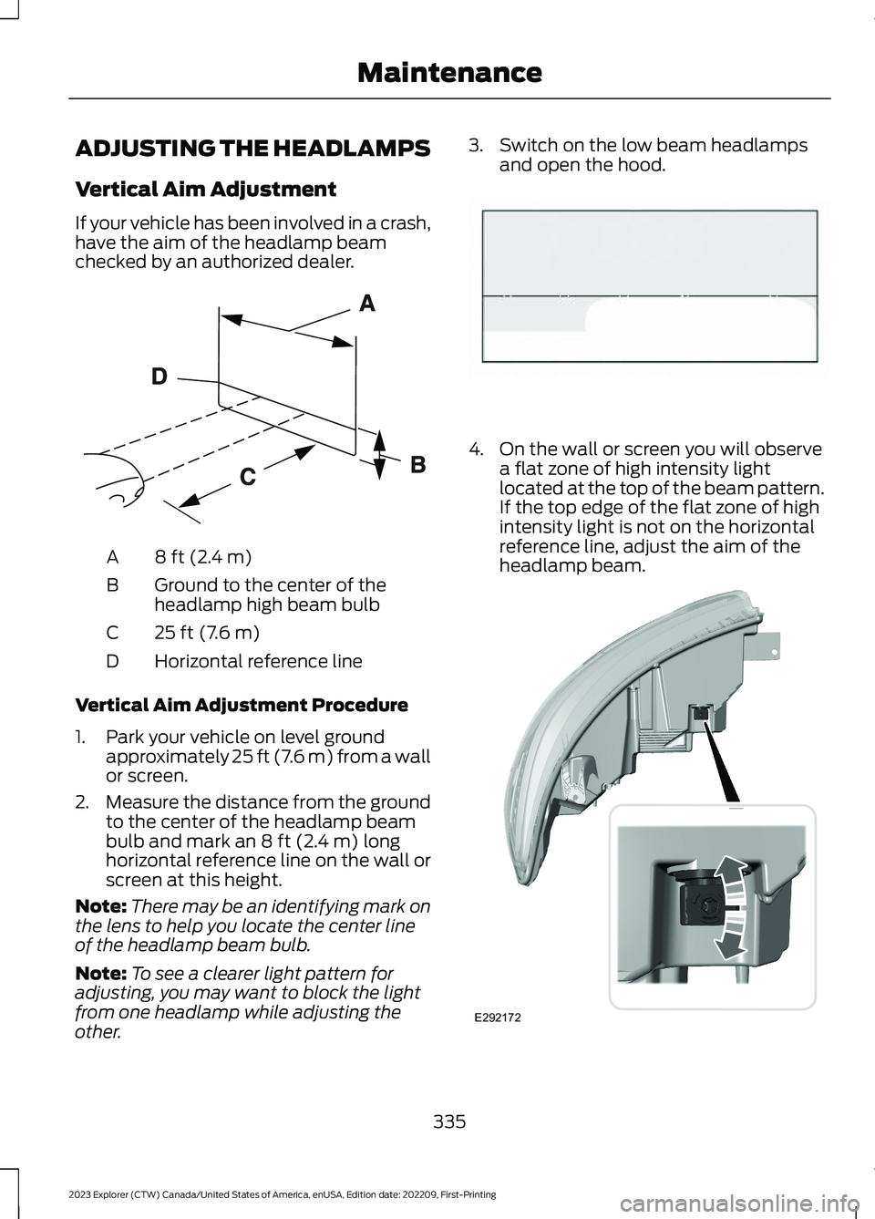
8 ft (2.4 m)A
Ground to the center of theheadlamp high beam bulbB
25 ft (7.6 m)C
Horizontal reference lineD
Vertical Aim Adjustment Procedure
1.Park your vehicle on level groundapproximately 25 ft (7.6 m) from a wallor screen.
2.Measure the distance from the groundto the center of the headlamp beambulb and mark an 8 ft (2.4 m) longhorizontal reference line on the wall orscreen at this height.
Note:There may be an identifying mark onthe lens to help you locate the center lineof the headlamp beam bulb.
Note:To see a clearer light pattern foradjusting, you may want to block the lightfrom one headlamp while adjusting theother.
3.Switch on the low beam headlampsand open the hood.
4.On the wall or screen you will observea flat zone of high intensity lightlocated at the top of the beam pattern.If the top edge of the flat zone of highintensity light is not on the horizontalreference line, adjust the aim of theheadlamp beam.
335
2023 Explorer (CTW) Canada/United States of America, enUSA, Edition date: 202209, First-PrintingMaintenanceE142592 E142465 E292172
Page 356 of 573

A.P: Indicates a tire, designatedby the Tire and Rim Association,that may be used for service oncars, sport utility vehicles,minivans and light trucks.Note: Ifyour tire size does not begin witha letter this may mean it isdesignated by either the EuropeanTire and Rim TechnicalOrganization or the Japan TireManufacturing Association.
B.215: Indicates the nominalwidth of the tire in millimetersfrom sidewall edge to sidewalledge. In general, the larger thenumber, the wider the tire.
C.65: Indicates the aspect ratiowhich gives the tire's ratio ofheight to width.
D.R: Indicates a radial type tire.
E.15: Indicates the wheel or rimdiameter in inches. If you changeyour wheel size, you will have topurchase new tires to match thenew wheel diameter.
F.95: Indicates the tire's loadindex. It is an index that relates tohow much weight a tire can carry.You may find this information inyour owner’s manual. If not,contact a local tire dealer.
Note:You may not find thisinformation on all tires because itis not required by federal law.
G.H: Indicates the tire's speedrating. The speed rating denotesthe speed at which a tire isdesigned to be driven for extendedperiods of time under a standardcondition of load and inflationpressure. The tires on your vehiclemay operate at differentconditions for load and inflationpressure. These speed ratings mayneed to be adjusted for thedifference in conditions. Theratings range from 81 mph(130 km/h) to 186 mph(299 km/h). These ratings arelisted in the following chart.
Note:You may not find thisinformation on all tires because itis not required by federal law.
Speed ratingLetterrating
81 mph (130 km/h)M
87 mph (140 km/h)N
99 mph (159 km/h)Q
106 mph (171 km/h)R
112 mph (180 km/h)S
118 mph (190 km/h)T
124 mph (200 km/h)U
130 mph (210 km/h)H
149 mph (240 km/h)V
352
2023 Explorer (CTW) Canada/United States of America, enUSA, Edition date: 202209, First-PrintingWheels and Tires
Page 360 of 573

C.80: Indicates the aspect ratiowhich gives the tire's ratio ofheight to width. Numbers of 70 orlower indicate a short sidewall.
D.D: Indicates a diagonal type tire.
R: Indicates a radial type tire.
E.16: Indicates the wheel or rimdiameter in inches. If you changeyour wheel size, you will have topurchase new tires to match thenew wheel diameter.
Recommended Tire Pressuresand Inflating Your Tires
Safe operation of your vehiclerequires that your tires areproperly inflated. Remember thata tire can lose up to half of its airpressure without appearing flat.
Every day before you drive, checkyour tires. If one looks lower thanthe others, use a tire gauge tocheck the pressure of all tires andadjust if required.
At least once a month and beforelong trips, inspect each tire andcheck the tire pressure with a tiregauge (including spare, ifequipped). Inflate all tires to theinflation pressure recommendedby the manufacturer.
WARNING: Under-inflationis the most common cause oftire failures and may result insevere tire cracking, treadseparation or blowout, withunexpected loss of vehicle
control and increased risk ofinjury. Under-inflation increasessidewall flexing and rollingresistance, resulting in heatbuildup and internal damage tothe tire. It also may result inunnecessary tire stress, irregularwear, loss of vehicle control andaccidents. A tire can lose up tohalf of its air pressure and notappear to be flat!
You are strongly urged to buy areliable tire pressure gauge, asautomatic service station gaugesmay be inaccurate. Werecommend the use of a digital ordial-type tire pressure gaugerather than a stick-type tirepressure gauge. Use therecommended cold inflationpressure for optimum tireperformance and wear.Under-inflation or over-inflationmay cause uneven treadwearpatterns.
Always inflate your tires to therecommended inflation pressureeven if it is less than the maximuminflation pressure informationfound on the tire. You will find aTire Label containing themanufactures recommended tireinflation pressure by the tire sizeand other important informationlocated on the B-Pillar or the edgeof the driver’s door).
356
2023 Explorer (CTW) Canada/United States of America, enUSA, Edition date: 202209, First-PrintingWheels and Tires
Page 361 of 573

The recommended tire inflationpressure is also found on theSafety Compliance CertificationLabel (affixed to either the doorhinge pillar, door-latch post, or thedoor edge that meets thedoor-latch on the B-pillar, or onthe edge of the driver’s door.
Failure to follow the tire pressurerecommendations can causeuneven treadwear patterns andadversely affect the way yourvehicle handles.
Inspecting Your Tires andWheel Valve Stems
Periodically inspect the tire treadsfor uneven or excessive wear andremove objects such as stones,nails or glass that may be wedged
in the tread grooves. Check the tireand valve stems for holes, cracks,or cuts that may permit airleakage and repair or replace thetire and replace the valve stem.Inspect the tire sidewalls forcracking, cuts, bruises and othersigns of damage or excessivewear. If internal damage to the tireis suspected, have the tiredismounted and inspected in caseit needs to be repaired or replaced.For your safety, tires that aredamaged or show signs ofexcessive wear should not be usedbecause they are more likely toblow out or fail.
Improper or inadequate vehiclemaintenance can cause tires towear abnormally. Inspect all yourtires, including the spare,frequently, and replace them ifone or more of the followingconditions exist:
Tire Wear
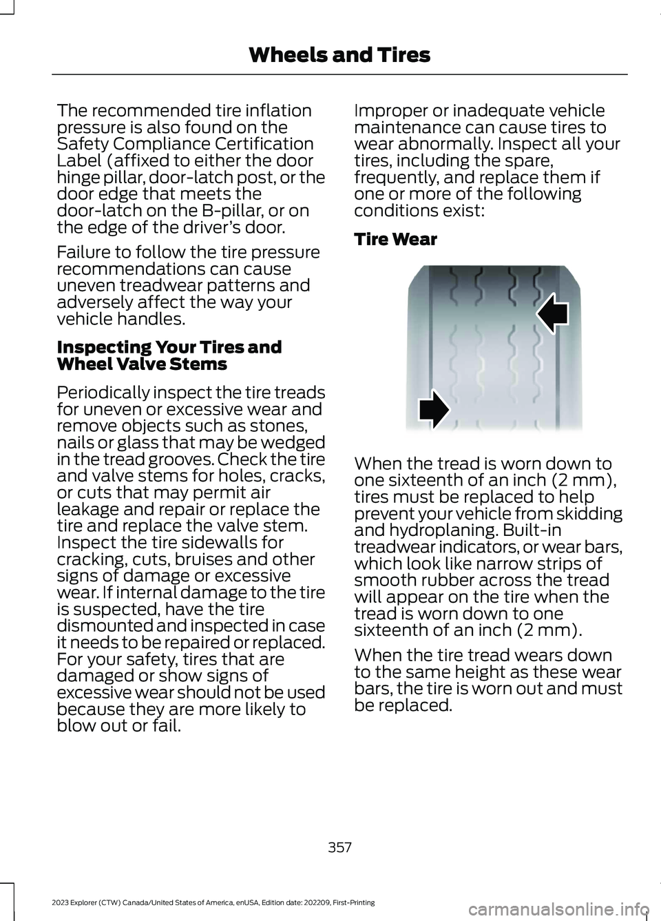
When the tread is worn down toone sixteenth of an inch (2 mm),tires must be replaced to helpprevent your vehicle from skiddingand hydroplaning. Built-intreadwear indicators, or wear bars,which look like narrow strips ofsmooth rubber across the treadwill appear on the tire when thetread is worn down to onesixteenth of an inch (2 mm).
When the tire tread wears downto the same height as these wearbars, the tire is worn out and mustbe replaced.
357
2023 Explorer (CTW) Canada/United States of America, enUSA, Edition date: 202209, First-PrintingWheels and TiresE142546
Page 379 of 573

18.Remove the jack and fully tighten thelug nuts in the order shown. SeeTechnical Specifications (page376).
19.If you enabled the Air SuspensionService Mode, switch the mode offprior to driving.
20.Remove the wheel blocks.
Stowing the jack
1.To store the folded wrench on the jack,engage the bracket of the jack baseand the lug wrench pin, swing thewrench upwards, adjust jack heightuntil the wrench hook engages the holeon jack. Tighten the hex nut clockwiseby hand until secure.
2.Place the jack in the spare tirecompartment, install the wing nut andtighten clockwise by hand until secure.
Stowing the flat tire
You cannot store the full-sized road wheelin the temporary spare tire well.
1.Find the flat tire retainer strap tuckedinside the jack channel. Lower thecarpeted load floor.
2.Stow the flat tire in the cargo area onthe load floor with the wheel facing up.Secure the flat tire with the retainerstrap by following the next steps.
3.Locate the rear left side and right sidecargo tie-down rings. Push the loop endof the retainer strap through one cargotie-down ring. Thread the non-loop endthrough the loop.
4.Weave the retainer strap through thewheel openings.
375
2023 Explorer (CTW) Canada/United States of America, enUSA, Edition date: 202209, First-PrintingWheels and Tires12345E306781 E176165 E142906 E294325