2023 DODGE HORNET length
[x] Cancel search: lengthPage 23 of 288

GETTING TO KNOW YOUR VEHICLE21
TO DISARM THE SYSTEM
The Vehicle Security system can be disarmed using any of
the following methods:
Push the unlock button on the key fob.
Grab the Passive Entry door handle to unlock the door
Úpage 23.
Cycle the ignition out of the OFF position to disarm the
system.
NOTE:
The driver's door key cylinder and liftgate button on the
key fob cannot arm or disarm the Vehicle Security
system. Use of the door key cylinder when the system
is armed will sound the alarm when the door is opened.
If the door is unlocked using the emergency key in the
driver’s door key cylinder when the alarm is active, the
alarm will not deactivate and will sound. The alarm can
then be disarmed by placing the ignition in the ON/RUN
position, or pushing the unlock button in the key fob.
The Vehicle Security system is designed to protect your
vehicle. However, you can create conditions where the
system will give you a false alarm. If one of the previously
described arming sequences has occurred, the Vehicle
Security system will arm regardless of whether you are in
the vehicle or not. If you remain in the vehicle and open a
door, the alarm will sound. If this occurs, disarm the
Vehicle Security system. If the Vehicle Security system is armed and the battery
becomes disconnected, the Vehicle Security system will
remain armed when the battery is reconnected; the
exterior lights will flash, and the horn will sound. If this
occurs, disarm the Vehicle Security system.
NOTE:The alarm does not turn off when the doors are unlocked
by inserting the blade of the emergency key (found inside
the key fob) into the door handle lock cylinder.
Disabling The System
To completely disable the system (e.g. during a lengthy
period of car inactivity), close the doors by turning the
emergency key in the door lock.
NOTE:If the key fob batteries become depleted, or the system
fails, the system can be switched off by cycling the ignition
out of the OFF position. Manually open the doors by
inserting the emergency key into the door lock cylinder,
and then place the key fob in the cupholder.
VOLUMETRIC/ANTI-LIFT PROTECTION —
I
F EQUIPPED
To ensure the correct operation of the Volumetric/Anti-Lift
Protection system, completely close the side windows and
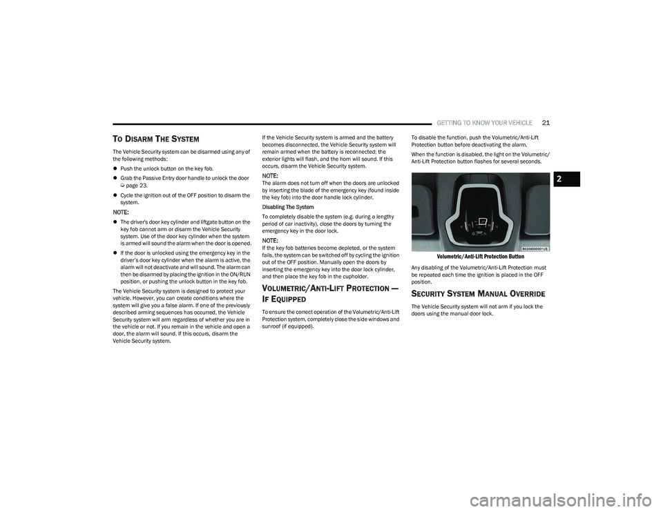
sunroof (if equipped). To disable the function, push the Volumetric/Anti-Lift
Protection button before deactivating the alarm.
When the function is disabled, the light on the Volumetric/
Anti-Lift Protection button flashes for several seconds.
Volumetric/Anti-Lift Protection Button
Any disabling of the Volumetric/Anti-Lift Protection must
be repeated each time the ignition is placed in the OFF
position.
SECURITY SYSTEM MANUAL OVERRIDE
The Vehicle Security system will not arm if you lock the
doors using the manual door lock.
2
23_GG_OM_EN_USC_t.book Page 21
Page 28 of 288

26GETTING TO KNOW YOUR VEHICLE
NOTE:
When the Child-Protection Door Lock system is
engaged, the door can be opened only by using the
outside door handle even though the inside door lock
is in the unlocked position.
After disengaging the Child-Protection Door Lock
system, always test the door from the inside to make
certain it is in the desired position.
After engaging the Child-Protection Door Lock system,
always test the door from the inside to make certain it
is in the desired position.
For emergency exit with the system engaged, rotate the
door lock button until the lock indicator is hidden
(unlocked position), lower the window, and open the
door with the outside door handle.
NOTE:Always use this device when carrying children. After
engaging the child lock on both rear doors, check for
effective engagement by trying to open a door with the
internal handle. Once the Child-Protection Door Lock
system is engaged, it is impossible to open the doors from
inside the vehicle. Before getting out of the vehicle, be
sure to check that there is no one left inside.
STEERING WHEEL
TILT/TELESCOPING STEERING COLUMN
This feature allows you to tilt the steering column upward
or downward. It also allows you to lengthen or shorten the
steering column. The tilt/telescoping lever is located
below the steering wheel at the end of the steering
column.
Tilt/Telescoping Lever
To unlock the steering column, push the control handle
downward (toward the floor). To tilt the steering column,
move the steering wheel upward or downward as desired.
To lengthen or shorten the steering column, pull the
steering wheel outward or push it inward as desired.
To lock the steering column in position, push the control
handle upward until fully engaged.
HEATED STEERING WHEEL —
I
F EQUIPPED
The steering wheel contains a heating element
that helps warm your hands in cold weather.
The heated steering wheel will begin to heat at
a fast, medium, or low level depending on the
current temperature of the steering wheel. Once the
heated steering wheel has been turned on, it will stay on
until the operator turns it off. The heated steering wheel
may not turn on when it is already warm.
To access the heated steering wheel button,
press the Comfort settings button within the
Uconnect system.
Press the heated steering wheel button once to turn
the heat on.
Press the heated steering wheel button a second time
to turn the heat off.
NOTE:The engine must be running for the heated steering wheel
to operate.
WARNING!
Avoid trapping anyone in a vehicle in a collision.
Remember that the rear doors can only be opened from
the outside when the Child-Protection locks are
engaged (locked).
WARNING!
Do not adjust the steering column while driving.
Adjusting the steering column while driving or driving
with the steering column unlocked, could cause the
driver to lose control of the vehicle. Failure to follow this
warning may result in serious injury or death.
23_GG_OM_EN_USC_t.book Page 26
Page 55 of 288

GETTING TO KNOW YOUR VEHICLE53
Your vehicle may also be equipped with a power outlet on
the back of the center console.
Rear Center Console Power Outlet — If Equipped
Power outlets labeled with a key symbol are powered
when the ignition is in the ON/RUN position.
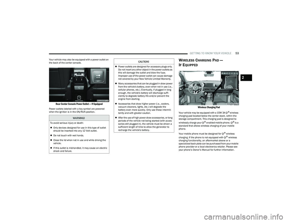
WIRELESS CHARGING PAD —
I
F EQUIPPED
Wireless Charging Pad
Your vehicle may be equipped with a 15W 3A Qi® wireless
charging pad located below the center stack, within the
storage compartment. This charging pad is designed to
wirelessly charge your Qi
® enabled mobile phone. Qi® is a
standard that allows wireless charging of your mobile
phone.
Your mobile phone must be designed for Qi
® wireless
charging. If the phone is not equipped with Qi® wireless
charging functionality, an aftermarket sleeve or a
specialized back plate can be purchased from your mobile
phone provider or a local electronics retailer. Please see
your phone’s Owner’s Manual for further information.
WARNING!
To avoid serious injury or death:
Only devices designed for use in this type of outlet
should be inserted into any 12 Volt outlet.
Do not touch with wet hands.
Close the lid when not in use and while driving the
vehicle.
If this outlet is mishandled, it may cause an electric
shock and failure.
CAUTION!
Power outlets are designed for accessory plugs only.
Do not insert any other object in the power outlets as
this will damage the outlet and blow the fuse.
Improper use of the power outlet can cause damage
not covered by your New Vehicle Limited Warranty.
Many accessories that can be plugged in draw power
from the vehicle's battery, even when not in use (i.e.,
cellular phones, etc.). Eventually, if plugged in long
enough, the vehicle's battery will discharge suffi -
ciently to degrade battery life and/or prevent the
engine from starting.
Accessories that draw higher power (i.e., coolers,
vacuum cleaners, lights, etc.) will degrade the
battery even more quickly. Only use these intermit -
tently and with greater caution.
After the use of high power draw accessories, or long
periods of the vehicle not being started (with acces -
sories still plugged in), the vehicle must be driven a
sufficient length of time to allow the generator to
recharge the vehicle's battery.
2
23_GG_OM_EN_USC_t.book Page 53
Page 109 of 288

STARTING AND OPERATING107
SIDE DISTANCE WARNING (SDW)
S
YSTEM
The Side Distance Warning system has the function of
detecting the presence of side obstacles near the vehicle
using the parking sensors located in the front and rear
fascias/bumpers.
Side Distance Warning Display
The Side Distance Warning screen will only be displayed if
this feature is enabled within Uconnect Settings
Úpage 130.
The system warns the driver with an acoustic signal, and
when selected, with visual indications on the radio
touchscreen display.
NOTE:ParkSense will reduce the volume of the radio if on when
the system is sounding an audible tone.
Activation/Deactivation
The system can operate only after driving a short distance
and if the vehicle speed is between 0 and 8 mph (0 and
13 km/h) while in DRIVE or NEUTRAL, or 7 mph (11 km/h) in REVERSE. The system can be activated/deactivated via
the Settings menu of the Uconnect system. If the
ParkSense System is deactivated via the ParkSense
switch, then the Side Distance Warning system will
automatically be deactivated.
Side Distance Warning System Status
NOTE:
The vehicle needs to be driven approximately one car
length in order for the Side Distance Warning system to
activate.
Before using ParkSense, it is strongly recommended
that the ball mount and hitch ball assembly be
disconnected from the vehicle when the vehicle is
not used for towing. Failure to do so can result in
injury or damage to vehicles or obstacles because
the hitch ball will be much closer to the obstacle than
the rear fascia/bumper when the vehicle sounds the
continuous tone. Also, the sensors could detect the
ball mount and hitch ball assembly, depending on its
size and shape, giving a false indication that an
obstacle is behind the vehicle.
CAUTION!
ParkSense is only a parking aid and it is unable to
recognize every obstacle, including small obstacles.
Parking curbs might be temporarily detected or not
detected at all. Obstacles located above or below the
sensors will not be detected when they are in close
proximity.
The vehicle must be driven slowly when using
ParkSense in order to be able to stop in time when an
obstacle is detected. It is recommended that the
driver looks over his/her shoulder when using
ParkSense.
WARNING!
WARNING ALERTS
Distance
(in/cm) Less than
12 inches
(30 cm)12 – 23 inches
(30 – 60 cm)
Arcs-Left Red Arc Yellow Arc
Arcs-Right Red Arc Yellow Arc
Audible Alert
Chime Audible alert only when the vehicle
is on course for a collision
Radio Volume
Reduced Yes
Yes
1 — System Not Active
2 — System Active
4
23_GG_OM_EN_USC_t.book Page 107
Page 152 of 288

150MULTIMEDIA
STEERING WHEEL AUDIO CONTROLS —
IF EQUIPPED
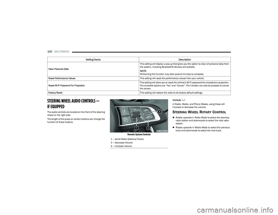
The audio controls are located on the front of the steering
wheel on the right side.
The length of the press on certain buttons can change the
function of these buttons.
Remote System Controls
Controls + / -
In Radio, Media, and Phone Modes, using these will
increase or decrease the volume.
STEERING WHEEL ROTARY CONTROL
Rotate upwards in Radio Mode to select the previous
radio station and downwards to select the next radio
station.
Rotate upwards in Media Mode to select the previous
track and downwards to select the next track.
Clear Personal Data
This setting will display a pop-up that gives you the option to clear all personal data from
the system, including Bluetooth® devices and presets.
NOTE:Performing this function may take several minutes to complete.
Reset Performance Values This setting will reset the performance values from your vehicle.
Reset Wi-Fi Password For Projection This setting will allow you to reset the vehicle’s Wi-Fi password for smartphone projection.
The available options are “Yes” and “Cancel”. The X button can also be pressed to cancel
the screen.
Factory Reset This setting will restore the radio to its factory default settings.
Setting NameDescription
1 — Scroll Radio Stations/Tracks
2 — Decrease Volume
3 — Increase Volume
23_GG_OM_EN_USC_t.book Page 150
Page 161 of 288

SAFETY159
AUXILIARY DRIVING SYSTEMS
BLIND SPOT MONITORING (BSM) —
I
F EQUIPPED
The BSM system uses two radar sensors, located inside
the rear fascia/bumper, to detect highway licensable
vehicles (automobiles, trucks, motorcycles, etc.) that
enter the blind spot zones from the rear/front/side of
the vehicle.
Rear Detection Zones
When the vehicle is started, the BSM Warning Light will
momentarily illuminate in both outside rearview mirrors to
let the driver know that the system is operational. The
BSM system sensors operate when the vehicle is in any
forward gear and enters standby mode when the vehicle is
in PARK. The BSM detection zone covers approximately one lane
width, 12 ft (3.8 m), on both sides of the vehicle.
The zone length starts at the outside mirror and extends
approximately 10 ft (3 m) beyond the rear fascia/bumper
of the vehicle. The BSM system monitors the detection
zones on both sides of the vehicle when the vehicle speed
reaches approximately 6 mph (10 km/h) or higher and will
alert the driver of vehicles in these areas.
NOTE:
The BSM system DOES NOT alert the driver about
rapidly approaching vehicles that are outside the
detection zones.
The BSM system will automatically disable when a
trailer is detected. If the attached trailer is not
detected, the system detection zone DOES NOT
change. Therefore, visually verify the adjacent lane is
clear for both your vehicle and trailer before making a
lane change. If the trailer or other object (i.e., bicycle,
sports equipment) extends beyond the side of your
vehicle, this may result in the BSM Warning Light
remaining illuminated the entire time the vehicle is in a
forward gear. It may be necessary to deactivate the
BSM system manually to avoid misdetection
Úpage 130. The BSM system can become blocked if snow, ice, mud, or
other road contaminations accumulate on the rear fascia/
bumper where the radar sensors are located. The system
may also detect blockage if the vehicle is operated in
areas with extremely low radar returns such as a desert or
parallel to a large elevation drop. If blockage is detected,
a “Blind Spot Temporarily Unavailable, Sensor Blocked”
message will display in the cluster, both mirror lights will
illuminate, and BSM and RCP alerts will not occur. This is
normal operation. The system will automatically recover
and resume function when the condition clears or when
an ignition cycle occurs. To minimize system blockage, do
not block the area of the rear fascia/bumper where the
radar sensors are located with foreign objects (bumper
stickers, bicycle racks, etc.) and keep it clear of road
contaminations.
Radar Sensor Location (Driver Side Shown)
6
23_GG_OM_EN_USC_t.book Page 159