Page 49 of 288

GETTING TO KNOW YOUR VEHICLE47
Recirculation Button
Press and release this button on the
touchscreen, or push the button on the
faceplate, to change the system between
automatic, recirculation, and outside air
modes. Recirculation can be used when outside
conditions such as smoke, odors, dust, or high humidity
are present. Recirculation can be used in all modes.
Recirculation may be unavailable (button on the
touchscreen grayed out) if conditions exist that could
create fogging on the inside of the windshield. The A/C can
be deselected manually without disturbing the mode
control selection. Continuous use of the Recirculation
mode may make the inside air stuffy and window fogging
may occur. Extended use of this mode is not
recommended.
AUTO Button
Press and release this button on the
touchscreen, or push the button on the
faceplate, to change the current setting. The
AUTO indicator illuminates when AUTO is on.
This feature automatically controls the interior cabin
temperature by adjusting distribution and amount of
airflow. Toggling this function will cause the system to
switch between manual override mode and automatic
modes
Úpage 49.
MAX Defrost Button
Press and release the touchscreen button, or
push and release the button on the faceplate,
to change the current airflow setting to Defrost
mode. The indicator illuminates when this
feature is on. Performing this function will cause the
automatic climate controls to change to manual mode,
and the following settings will occur:
The blower speed increases to full (all LEDs on)
NOTE:The blower speed increases to full only if warm outlet
temperature can be guaranteed. Otherwise, the blower
bars will be proportional to outlet air temperature.
The air conditioning compressor is turned on
(A/C LED off)
Both driver and passenger temperature controls are
set to HI
Defrost mode is selected (LED on)
Rear defroster is turned on (LED on)
The air recirculation is turned off (LED off)
If MAX Defrost mode is turned off, the Climate Control
system will return to the previous setting. MAX Defrost
automatically turns off after a few minutes.
Rear Defrost Button
Press and release the button on the
touchscreen, or push and release the button on
the faceplate, to turn on the rear window
defroster and the heated outside mirrors
(if equipped). The Rear Defrost indicator illuminates when
the rear window defroster is on. The rear window defroster
automatically turns off after 10 minutes.
CAUTION!
Failure to follow these cautions can cause damage to
the heating elements:
Use care when washing the inside of the rear
window. Do not use abrasive window cleaners on the
interior surface of the window. Use a soft cloth and a
mild washing solution, wiping parallel to the heating
elements. Labels can be peeled off after soaking
with warm water.
Do not use scrapers, sharp instruments, or abrasive
window cleaners on the interior surface of the
window.
Keep all objects a safe distance from the window.
2
23_GG_OM_EN_USC_t.book Page 47
Page 50 of 288

48GETTING TO KNOW YOUR VEHICLE
Driver And Passenger Temperature
Control Buttons
These buttons provide the driver and passenger with
independent temperature control.
SYNC Button
Press the SYNC button on the touchscreen to
toggle the Sync feature on/off. The SYNC
indicator is illuminated when SYNC is on. SYNC
is used to synchronize the passenger
temperature setting with the driver temperature setting.
Changing the passenger temperature setting while in
SYNC will automatically exit this feature.
NOTE:The SYNC button is only available on the touchscreen.
Blower Control
Blower Control is used to regulate the amount of
air forced through the Climate Control system.
There are seven blower speeds available.
Adjusting the blower will cause automatic mode
to switch to manual operation. The speeds can be selected
using either the blower control buttons on the faceplate or
the buttons on the touchscreen.
Faceplate
Press the small blower icon button to decrease the blower
speed, or press the large blower icon button to increase
the blower speed.
Touchscreen
Blower speed can also be selected by pressing a number
on the blower bar area.
Mode Control
Select Mode by pressing one of the Mode
buttons on the touchscreen, or the faceplate,
to change the airflow distribution mode. The
airflow distribution mode can be adjusted so air
comes from the instrument panel outlets, floor outlets,
defrost outlets and demist outlets.
Panel Mode
Air comes from the outlets in the instrument
panel. Each of these outlets can be individually
adjusted to direct the flow of air. The air vanes
of the center outlets and outboard outlets can
be moved up and down or side to side to regulate airflow
direction. There is a shut-off wheel located below the air
vanes to shut off or adjust the amount of airflow from
these outlets.
Bi-Level Mode
Air comes from the instrument panel outlets
and floor outlets. A slight amount of air is
directed through the defrost and side window
demister outlets.
NOTE:Bi-Level mode is designed under comfort conditions to
provide cooler air out of the panel outlets and warmer air
from the floor outlets.
Floor Mode
Air comes from the floor outlets. A slight
amount of air is directed through the defrost,
side window demister outlets, and panel
outboard outlets.
Defrost Mode
Air comes from the windshield and side
window demist outlets. When the defrost
button is selected, the blower level may
increase. Use Defrost mode with maximum
temperature settings for best windshield and side window
defrosting and defogging. When toggling the front defrost
mode button, the Climate Control system will return to the
previous setting.
Mix Mode
Air is directed through the floor, defrost, and
side window demister outlets. This setting
works best in cold or snowy conditions that
require extra heat to the windshield. This
setting is good for maintaining comfort while reducing
moisture on the windshield. A slight amount of air is also
directed through the panel outboard outlets.
Push upward on the driver’s or
passenger’s side toggle switch on the
faceplate, or press and slide the
temperature bar towards the red arrow
button on the touchscreen for warmer
temperature settings.
Push downward the driver’s or
passenger’s side toggle switch on the
faceplate, or press and slide the
temperature bar towards the blue arrow
button on the touchscreen for cooler
temperature settings.
23_GG_OM_EN_USC_t.book Page 48
Page 51 of 288

GETTING TO KNOW YOUR VEHICLE49
Combine Modes
Dual Level Combination
Front Defrost and Panel Mode
Tri-Level Combination
Front Defrost, Panel Mode, and Floor Mode
Climate Control OFF Button
Press and release this button on the
touchscreen, or push and release the
button on the faceplate to turn the
Climate Control ON/OFF.
AUTOMATIC TEMPERATURE
CONTROL (ATC)
Automatic Operation
1. Push the AUTO button on the faceplate, or the
AUTO button on the touchscreen (if equipped) on the
Automatic Temperature Control (ATC) Panel.
2. Next, adjust the temperature you would like the system to maintain by adjusting the temperature
control buttons. Once the desired temperature is
displayed, the system achieves and automatically
maintains that comfort level.
3. When the system is set up for your comfort level, it is not necessary to change the settings. You experience
the greatest efficiency by simply allowing the system
to function automatically.
NOTE:
It is not necessary to move the temperature settings for
cold or hot vehicles. The system automatically adjusts
the temperature, mode, and blower speed to provide
comfort as quickly as possible.
The temperature can be displayed in US or Metric units
by selecting the US/Metric customer-programmable
feature.
To provide you with maximum comfort in the Automatic
mode during cold start-ups, the blower fan remains on low
until the engine warms up. The blower increases in speed
and transition into Auto mode.
Manual Operation Override
This system offers a full complement of manual override
features. The AUTO symbol in the front ATC display will be
turned off when the system is being used in the manual
mode.
CLIMATE VOICE COMMANDS
Adjust vehicle temperatures hands-free and keep
everyone comfortable while you keep moving ahead.
Push the VR button on the steering wheel. After the beep,
say one of the following commands:
“Set the driver temperature to 70 degrees ”
“Set the passenger temperature to 70 degrees ”
Did You Know: Voice Command for Climate may only be
used to adjust the interior temperature of your vehicle.
Voice Command will not work to adjust the heated seats
or steering wheel if equipped.
OPERATING TIPS
Refer to the chart at the end of this section for suggested
control settings for various weather conditions.
Summer Operation
The engine cooling system must be protected with a
high-quality antifreeze coolant to provide proper corrosion
protection and to protect against engine overheating.
OAT coolant (conforming to MS.90032) is recommended.
The driver or front passenger can combine
two or three of the modes described by
selecting them individually on the climate
control screen. Combine modes by
pressing each icon on the touchscreen.
2
23_GG_OM_EN_USC_t.book Page 49
Page 52 of 288

50GETTING TO KNOW YOUR VEHICLE
Winter Operation
To ensure the best possible heater and defroster
performance, make sure the engine cooling system is
functioning properly and the proper amount, type, and
concentration of coolant is used. Use of the Air
Recirculation mode during Winter months is not
recommended, because it may cause window fogging.
Vacation/Storage
For information on maintaining the Climate Control system
when the vehicle is being stored for an extended period of
time, see
Úpage 261.
Window Fogging
Vehicle windows tend to fog on the inside in mild, rainy,
and/or humid weather. To clear the windows, select
Defrost or Mix mode and increase the front blower speed.
Do not use the Recirculation mode without A/C for long
periods, as fogging may occur.
Outside Air Intake
Make sure the air intake, located directly in front of the
windshield, is free of obstructions, such as leaves. Leaves
collected in the air intake may reduce airflow, and if they
enter the air distribution box, they could plug the water
drains. In Winter months, make sure the air intake is clear
of ice, slush, and snow.
Cabin Air Filter
The Climate Control system filters out dust and pollen
from the air. Contact an authorized dealer to service your
cabin air filter, and to have it replaced when needed.
Operating Tips ChartINTERIOR STORAGE AND EQUIPMENT
STORAGE
Glove Compartment
The glove compartment is located on the passenger side
of the instrument panel.
Glove Compartment
To open the glove compartment, pull the release handle.
WEATHER CONTROL SETTINGS
Hot Weather And Vehicle
Interior Is Very Hot Set the mode control to
(Panel Mode),
(MAX A/C) on, and
blower on high. Roll down the windows for a minute to flush out the hot air. Adjust the controls as needed to achieve comfort.
Warm Weather Turn (A/C) on and set
the mode control to
(Panel Mode).
Cool Sunny Operate in (Bi-Level
Mode).
Cool & Humid Conditions Set the mode control to
(Mix Mode) and turn (A/C) on to keep
windows clear.
Cold Weather Set the mode control to
(Floor Mode). If
windshield fogging starts
to occur, move the control
to (Mix Mode).
WARNING!
Do not operate this vehicle with a glove compartment in
the open position. Driving with the glove compartment
open may result in injury in a collision.
23_GG_OM_EN_USC_t.book Page 50
Page 53 of 288

GETTING TO KNOW YOUR VEHICLE51
Console Storage Compartment
To open, pull up on the latch and lift the cover.
Center Console
The center console has a storage area which can hold cell
phones, PDAs, and other small items.
The center console can slide forward and rearward for
comfort.
Door Storage
Front Door Storage
Storage areas are located in the door trim panels.
Rear Door Storage
Storage areas are located in the door trim panels.
USB CONTROL
This vehicle has data/charge ports for type USB A and C
located on the central dashboard. For versions/markets
where provided, the USB A and C port located on the back
of the central console under the air vents are charge only.
Both USB C ports, for versions/markets where provided,
are Power Delivery 3.0, providing fast charging up to 40W.
Plugging in a smartphone device to a USB data/charge
port will activate Android Auto™ or Apple CarPlay
®
features, if equipped. For further information, refer to
“Android Auto™” or “Apple CarPlay
®” in the Uconnect
Radio Instruction Manual.
NOTE:Two devices can be plugged in at the same time, and both
ports will provide charging capabilities. Only one port can
transfer data to the system at a time.
For example, if a device is plugged into the Type A USB port
and another device is plugged into the Type C USB port, a
message will appear and allow you to select which device
to use. Different scenarios are listed here when a non-phone
device is plugged into the smaller and larger USB ports,
and when a phone device is plugged into the smaller and
larger USB ports:
“A new device is now connected. Previous connection
was lost.”
“(Phone Name) now connected. Previous connection
was lost.”
“Another device is in use through the same USB port.
Please disconnect the first device to use the second
device.”
Plugging in a phone or another USB device may cause the
connection to a previous device to be lost.
Front USB Ports
WARNING!
Do not operate this vehicle with a console compartment
lid in the open position. Driving with the console
compartment lid open may result in injury in a collision.
1 — Type C USB Port
2 — Type A USB Port
2
23_GG_OM_EN_USC_t.book Page 51
Page 54 of 288

52GETTING TO KNOW YOUR VEHICLE
By using a USB cable to connect an external device:
The device can be played on the vehicle’s sound
system, providing the artist, track title, and album infor -
mation on the radio display.
NOTE:Depending on track configuration, track information may
not be present on the radio display.
The device can be controlled using the radio buttons to
play, and browse the contents of the device.
The audio device battery charges when plugged into
the USB port.
The second row USB ports can be used to charge an
external device. These ports are charge only.
Charge Only Rear USB Ports
Both the front and rear USB C port have the ability for fast
charging. They are Power Delivery 3.0 and can provide
charging up to 40W.
NOTE:Charge unsupported devices with the Charge Only USB
ports. If an unsupported device is plugged into a Media
USB port, a message will display on the touchscreen that
the device is not supported by the system.
POWER OUTLETS — IF EQUIPPED
Your vehicle may be equipped with 12 Volt (13 Amp)
power outlets that can be used to power cellular phones,
small electronics and other low powered electrical
accessories.
The Instrument Panel Power Outlet is located in the
storage compartment under the climate control buttons. It
will only operate when the ignition is in the ON/RUN
position.
Power Outlet
NOTE:
Do not connect devices, with a power rating higher than
180 W, to the outlet. Do not use power adapters that
do not fit the outlet as this may damage it.
All accessories connected to the battery powered
outlets should be removed or turned off when the
vehicle is not in use to protect the battery against
discharge.
If equipped, a power outlet is located in the rear cargo
area.
Rear Cargo Area Power Outlet — If Equipped
NOTE:
The rear cargo area power outlet can be switched from
ignition powered to battery powered. See an authorized
dealer for details.
1 — Type C USB Port
2 — Type A USB Port
23_GG_OM_EN_USC_t.book Page 52
Page 55 of 288

GETTING TO KNOW YOUR VEHICLE53
Your vehicle may also be equipped with a power outlet on
the back of the center console.
Rear Center Console Power Outlet — If Equipped
Power outlets labeled with a key symbol are powered
when the ignition is in the ON/RUN position.
WIRELESS CHARGING PAD —
I
F EQUIPPED
Wireless Charging Pad
Your vehicle may be equipped with a 15W 3A Qi® wireless
charging pad located below the center stack, within the
storage compartment. This charging pad is designed to
wirelessly charge your Qi
® enabled mobile phone. Qi® is a
standard that allows wireless charging of your mobile
phone.
Your mobile phone must be designed for Qi
® wireless
charging. If the phone is not equipped with Qi® wireless
charging functionality, an aftermarket sleeve or a
specialized back plate can be purchased from your mobile
phone provider or a local electronics retailer. Please see
your phone’s Owner’s Manual for further information.
WARNING!
To avoid serious injury or death:
Only devices designed for use in this type of outlet
should be inserted into any 12 Volt outlet.
Do not touch with wet hands.
Close the lid when not in use and while driving the
vehicle.
If this outlet is mishandled, it may cause an electric
shock and failure.
CAUTION!
Power outlets are designed for accessory plugs only.
Do not insert any other object in the power outlets as
this will damage the outlet and blow the fuse.
Improper use of the power outlet can cause damage
not covered by your New Vehicle Limited Warranty.
Many accessories that can be plugged in draw power
from the vehicle's battery, even when not in use (i.e.,
cellular phones, etc.). Eventually, if plugged in long
enough, the vehicle's battery will discharge suffi -
ciently to degrade battery life and/or prevent the
engine from starting.
Accessories that draw higher power (i.e., coolers,
vacuum cleaners, lights, etc.) will degrade the
battery even more quickly. Only use these intermit -
tently and with greater caution.
After the use of high power draw accessories, or long
periods of the vehicle not being started (with acces -
sories still plugged in), the vehicle must be driven a
sufficient length of time to allow the generator to
recharge the vehicle's battery.
2
23_GG_OM_EN_USC_t.book Page 53
Page 56 of 288

54GETTING TO KNOW YOUR VEHICLE
The wireless charging pad is equipped with an anti-slip
mat to hold your mobile phone in place, and an LED
indicator light.
Place the device inside the prepared area delimited in the
mat as shown in the image. Incorrect positioning will
prevent the phone from charging.
Correct Phone Position
LED Indicator Status:
No Light: Charging pad is idle or searching for a device.
Device may not be compatible with the Qi
® standard.
Blue Light: Device is detected and is charging.
Red Light/Flashing: Internal error, or foreign object is
detected.
Green Light: Device has completed battery charging
(if device is equipped to transmit this information). Important Notes Regarding This Vehicle’s Wireless
Charging Pad:
The presence of the NFC function active on a smart -
phone could signal malfunction anomalies.
The ignition must be in the ON/RUN position in order
for the phone to charge.
To avoid interference with the key fob search, the wire -
less charging pad will stop charging when any door is
opened.
Be sure to place the mobile device correctly (display
facing upward, and phone not covering the LED) on the
wireless charging pad.
Wireless charging is not as fast as when the phone is
connected to a wired charger.
The phone’s protective case must be removed when
placed on the wireless charging pad.
iPhone
® 12 (including iPod®) is equipped with soft -
ware to protect the device from overheating. When the
software is active, the rate of charge is slowed down to
protect the device.
Phones must always be placed on the wireless
charging pad within the outline shown on the pad so
that its charging parts connect with the charging coils
of the system. Movement of the phone during charging
may prevent or slow the rate of charge.
Having multiple applications open on the phone while
charging will reduce the charging efficiency, and may
even shut down an application that is actively running
(i.e. Apple CarPlay
®). This may also cause the phone to
overheat.
Wireless chargers may implement certain methods to
prevent the phone from overheating during charging
such as slowing down the rate of charge. In certain
instances, the device may shut down for a brief period
of time (when the device reaches a certain tempera -
ture). If this happens, it does not mean there is a fault
with the wireless charging pad. This may just be a
protective measure to prevent damage to the phone.
The use of multiple wireless functions at the same time
(wireless charging, Apple CarPlay
®, Android Auto™)
could cause the device to overheat, resulting in limita -
tion of the functions or it turning off. In this case, it is
recommended to connect the system using t
he USB port.
Do not place the key fob or any other type of metal/
magnetized object inside the mobile phone housing or
near the wireless charging pad.
CAUTION!
The key fob should not be placed on the charging pad
or within 6 inches (15 cm) of it. Doing so can cause
excessive heat buildup and damage to the fob. Placing
the fob in close proximity of the charging pad blocks the
fob from being detected by the vehicle and prevents the
vehicle from starting.
23_GG_OM_EN_USC_t.book Page 54
 1
1 2
2 3
3 4
4 5
5 6
6 7
7 8
8 9
9 10
10 11
11 12
12 13
13 14
14 15
15 16
16 17
17 18
18 19
19 20
20 21
21 22
22 23
23 24
24 25
25 26
26 27
27 28
28 29
29 30
30 31
31 32
32 33
33 34
34 35
35 36
36 37
37 38
38 39
39 40
40 41
41 42
42 43
43 44
44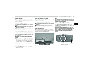 45
45 46
46 47
47 48
48 49
49 50
50 51
51 52
52 53
53 54
54 55
55 56
56 57
57 58
58 59
59 60
60 61
61 62
62 63
63 64
64 65
65 66
66 67
67 68
68 69
69 70
70 71
71 72
72 73
73 74
74 75
75 76
76 77
77 78
78 79
79 80
80 81
81 82
82 83
83 84
84 85
85 86
86 87
87 88
88 89
89 90
90 91
91 92
92 93
93 94
94 95
95 96
96 97
97 98
98 99
99 100
100 101
101 102
102 103
103 104
104 105
105 106
106 107
107 108
108 109
109 110
110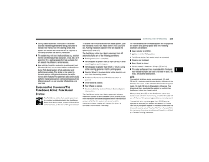 111
111 112
112 113
113 114
114 115
115 116
116 117
117 118
118 119
119 120
120 121
121 122
122 123
123 124
124 125
125 126
126 127
127 128
128 129
129 130
130 131
131 132
132 133
133 134
134 135
135 136
136 137
137 138
138 139
139 140
140 141
141 142
142 143
143 144
144 145
145 146
146 147
147 148
148 149
149 150
150 151
151 152
152 153
153 154
154 155
155 156
156 157
157 158
158 159
159 160
160 161
161 162
162 163
163 164
164 165
165 166
166 167
167 168
168 169
169 170
170 171
171 172
172 173
173 174
174 175
175 176
176 177
177 178
178 179
179 180
180 181
181 182
182 183
183 184
184 185
185 186
186 187
187 188
188 189
189 190
190 191
191 192
192 193
193 194
194 195
195 196
196 197
197 198
198 199
199 200
200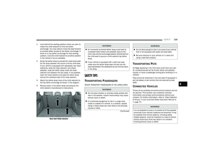 201
201 202
202 203
203 204
204 205
205 206
206 207
207 208
208 209
209 210
210 211
211 212
212 213
213 214
214 215
215 216
216 217
217 218
218 219
219 220
220 221
221 222
222 223
223 224
224 225
225 226
226 227
227 228
228 229
229 230
230 231
231 232
232 233
233 234
234 235
235 236
236 237
237 238
238 239
239 240
240 241
241 242
242 243
243 244
244 245
245 246
246 247
247 248
248 249
249 250
250 251
251 252
252 253
253 254
254 255
255 256
256 257
257 258
258 259
259 260
260 261
261 262
262 263
263 264
264 265
265 266
266 267
267 268
268 269
269 270
270 271
271 272
272 273
273 274
274 275
275 276
276 277
277 278
278 279
279 280
280 281
281 282
282 283
283 284
284 285
285 286
286 287
287