2023 DODGE CHARGER spare tire
[x] Cancel search: spare tirePage 211 of 292

IN CASE OF EMERGENCY209
5. Raise the vehicle just enough to remove the flat tire
and install the spare tire.
6. Remove the lug nuts and tire.
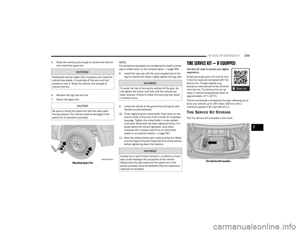
7. Mount the spare tire.
Mounting Spare Tire
NOTE:
For vehicles so equipped, do not attempt to install a center
cap or wheel cover on the compact spare Úpage 259.
8. Install the lug nuts with the cone shaped end of the lug nut toward the wheel. Lightly tighten the lug nuts.
9. Lower the vehicle to the ground by turning the jack handle counterclockwise.
10. Finish tightening the wheel bolts. Push down on the wrench while at the end of the handle for increased
leverage. Tighten the wheel bolts in a star pattern
until each wheel bolt has been tightened twice. If in
doubt about the correct tightness, have them
checked with a torque wrench by an authorized
dealer or at a service station
Úpage 267.
11. Stow the wheel chocks, jack, tools and flat tire. Make sure the base of the jack faces the front of the vehicle
before tightening down the fastener.
TIRE SERVICE KIT — IF EQUIPPED
Use this QR code to access your digital
experience.
Small punctures up to 1/4 inch (6 mm)
in the tire tread can be sealed with Tire
Service Kit. Foreign objects (e.g.,
screws or nails) should not be removed
from the tire. Tire Service Kit can be
used in outside temperatures down to
approximately -4°F (-20°C).
This kit will provide a temporary tire seal, allowing you to
drive your vehicle up to 100 miles (160 km) with a
maximum speed of 50 mph (80 km/h).
TIRE SERVICE KIT STORAGE
The Tire Service Kit is located in the trunk.
Tire Service Kit Location
WARNING!
Raising the vehicle higher than necessary can make the
vehicle less stable. It could slip off the jack and hurt
someone near it. Raise the vehicle only enough to
remove the tire.
CAUTION!
Be sure to mount the spare tire with the valve stem
facing outward. The vehicle could be damaged if the
spare tire is mounted incorrectly.
WARNING!
To avoid the risk of forcing the vehicle off the jack, do
not tighten the wheel nuts fully until the vehicle has
been lowered. Failure to follow this warning may result
in serious injury.
WARNING!
A loose tire or jack thrown forward in a collision or hard
stop could endanger the occupants of the vehicle.
Always stow the jack parts and the spare tire in the
places provided. Have the deflated (flat) tire repaired or
replaced immediately.
7
23_LD_OM_EN_USC_t.book Page 209
Page 217 of 292

IN CASE OF EMERGENCY215
4. Connect the opposite end of the negative (-) jumper
cable to the remote negative (-) post (exposed
metallic/unpainted post of the discharge vehicle)
located directly behind the underhood fuse box.
5. Start the engine in the vehicle that has the booster battery, let the engine idle a few minutes, and then
start the engine in the vehicle with the discharged
battery.
6. Once the engine is started, follow the disconnection procedure.
Disconnecting The Jumper Cables
1. Disconnect the negative
(-) end of the jumper cable
from the remote negative (-)
post of the vehicle with
the discharged battery.
2. Disconnect the opposite end of the negative (-)
jumper cable from the negative (-) post of the booster
battery. 3. Disconnect the positive
(+) end of the jumper cable
from the positive (+) post of the booster battery.
4. Disconnect the opposite end of the positive (+)
jumper cable from the remote positive (+) post of the
vehicle with the discharged battery, and reinstall the
protective cap.
If frequent jump starting is required to start your vehicle
you should have the battery and charging system
inspected at an authorized dealer.
REFUELING IN EMERGENCY
The vehicle is equipped with a refueling funnel for a
Cap-Less Fuel System. The funnel is located under the
access cover in the trunk. If refueling is necessary, while
using an approved gas can, insert the refueling funnel into
the filler neck opening. Take care to open both flappers
with the funnel to avoid spills.
NOTE:In certain cold conditions, ice may prevent the fuel door
from opening. If this occurs, lightly push on the fuel door
to break the ice buildup and re-release the fuel door using
the inside release button. Do not pry on the door.
Fuel Funnel Location
Emergency Refueling Funnel
Most gas cans will not open the flapper doors. A funnel is
provided to allow emergency refueling with a gas can.
See the following steps for refueling:
1. Retrieve funnel from the spare tire storage area.
2. Insert funnel into same filler pipe opening as the fuel nozzle.
Inserting Funnel
WARNING!
Do not connect the jumper cable to the negative (-) post
of the discharged battery. The resulting electrical spark
could cause the battery to explode and could result in
personal injury.
CAUTION!
Do not run the booster vehicle engine above 2,000
RPM since it provides no charging benefit, wastes fuel,
and can damage booster vehicle engine.
CAUTION!
Accessories plugged into the vehicle power outlets draw
power from the vehicle’s battery, even when not in use
(i.e., cellular devices, etc.). Eventually, if plugged in long
enough without engine operation, the vehicle’s battery
will discharge sufficiently to degrade battery life and/or
prevent the engine from starting.
7
23_LD_OM_EN_USC_t.book Page 215
Page 218 of 292

216IN CASE OF EMERGENCY
3. Ensure funnel is inserted fully to hold flapper doors
open.
4. Pour fuel into funnel opening.
5. Remove funnel from filler pipe, clean off prior to putting back in the spare tire storage area.IF YOUR ENGINE OVERHEATS
If the vehicle is overheating, it will need to be serviced by
an authorized dealer.
Potential signs of vehicle overheating:
Temperature gauge is at HOT (H)
Strong smell of coolant
White smoke coming from engine or exhaust
Coolant bottle coolant has bubbles present
In the event it is observed that the temperature gauge is
moving towards or close to the HOT (H) position, you can
reduce the potential for overheating by taking the
appropriate action.
On the highways — slow down.
In city traffic — while stopped, place the transmission in
NEUTRAL (N), but do not increase the engine idle speed
while preventing vehicle motion with the brakes.
If your Air Conditioner (A/C) is on, turn it off. The A/C
system adds heat to the engine cooling system and
turning the A/C off can help remove this heat.
You can also turn the temperature control to maximum
heat, the mode control to floor and the blower control
to high. This allows the heater core to act as a supple -
ment to the radiator and aids in removing heat from the
engine cooling system.
MANUAL PARK RELEASE–8–SPEED
TRANSMISSION
CAUTION!
To avoid fuel spillage and overfilling, do not “top off” the
fuel tank after filling.
WARNING!
Never have any smoking materials lit in or near the
vehicle when the fuel door is open or the tank is
being filled.
Never add fuel when the engine is running. This is in
violation of most state and federal fire regulations
and may cause the Malfunction Indicator Light to
turn on.
A fire may result if fuel is pumped into a portable
container that is inside of a vehicle. You could be
burned. Always place fuel containers on the ground
while filling.
WARNING!
You or others can be badly burned by hot engine
coolant (antifreeze) or steam from your radiator. If you
see or hear steam coming from under the hood, do not
open the hood until the radiator has had time to cool.
Never try to open a cooling system pressure cap when
the radiator or coolant bottle is hot.
CAUTION!
Driving with a hot cooling system could damage your
vehicle. If the temperature gauge reads HOT (H), pull
over and stop the vehicle. Idle the vehicle with the air
conditioner turned off until the pointer drops back into
the normal range. If the pointer remains on HOT (H),
and you hear continuous chimes, turn the engine off
immediately and call for service.
WARNING!
Always secure your vehicle by fully applying the parking
brake before activating the Manual Park Release. In
addition, you should be seated in the driver's seat with
your foot firmly on the brake pedal when activating the
Manual Park Release. Activating the Manual Park
Release will allow your vehicle to roll away if it is not
secured by the parking brake, or by proper connection
to a tow vehicle. Activating the Manual Park Release on
an unsecured vehicle could lead to serious injury or
death for those in or around the vehicle.
23_LD_OM_EN_USC_t.book Page 216
Page 244 of 292

242SERVICING AND MAINTENANCE
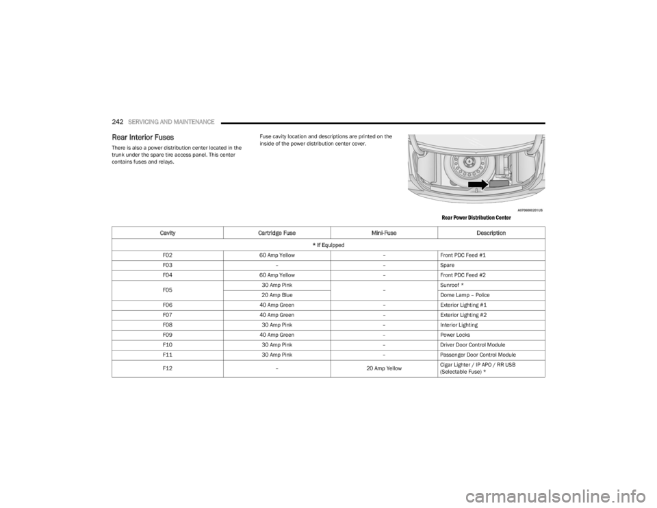
Rear Interior Fuses
There is also a power distribution center located in the
trunk under the spare tire access panel. This center
contains fuses and relays. Fuse cavity location and descriptions are printed on the
inside of the power distribution center cover.
Rear Power Distribution Center
Cavity
Cartridge Fuse Mini-FuseDescription
* If Equipped
F02 60 Amp Yellow –Front PDC Feed #1
F03 ––Spare
F04 60 Amp Yellow –Front PDC Feed #2
F05 30 Amp Pink
–Sunroof *
20 Amp Blue Dome Lamp – Police
F06 40 Amp Green –Exterior Lighting #1
F07 40 Amp Green –Exterior Lighting #2
F08 30 Amp Pink –Interior Lighting
F09 40 Amp Green –Power Locks
F10 30 Amp Pink –Driver Door Control Module
F11 30 Amp Pink –Passenger Door Control Module
F12 –20 Amp YellowCigar Lighter / IP APO / RR USB
(Selectable Fuse) *
23_LD_OM_EN_USC_t.book Page 242
Page 245 of 292

SERVICING AND MAINTENANCE243
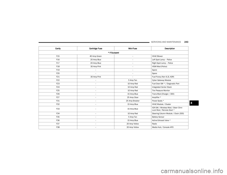
F15 40 Amp Green –HVAC Blower
F16 20 Amp Blue –Left Spot Lamp – Police
F17 20 Amp Blue –Right Spot Lamp – Police
F18 30 Amp Pink –VISM Mod (Police)
F19 ––Spare
F20 ––Spare
F21 30 Amp Pink –Fuel Pump (Non 6.2L ADR)
F22 –5 Amp TanCyber Gateway Module
F23 –10 Amp RedFuel Door SW * / Diagnostic Port
F24 –10 Amp RedIntegrated Center Stack
F25 –10 Amp RedTire Pressure Monitor
F26 –15 Amp BlueTrans Mod (Charger / 300)
F27 –25 Amp ClearAmplifier *
F31 –25 Amp BreakerPower Seats *
F32 –15 Amp BlueHVAC Module / Cluster
F33 –15 Amp BlueIGN SW / Wireless Mod / Steer Clmn
Lock Mod / Remote Start *
F34 –10 Amp RedSteering Column Module / Clock (300)
F35 –5 Amp TanBattery Sensor
F36 –15 Amp BlueActive Exhaust Valve *
F37 –20 Amp YellowRadio
F38 –20 Amp YellowMedia Hub / Console APO
Cavity Cartridge Fuse Mini-FuseDescription
* If Equipped
8
23_LD_OM_EN_USC_t.book Page 243
Page 250 of 292

248SERVICING AND MAINTENANCE
TIRES
TIRE SAFETY INFORMATION
Tire safety information will cover aspects of the following
information: Tire Markings, Tire Identification Numbers,
Tire Terminology and Definitions, Tire Pressures, and Tire
Loading.
Tire Markings
Tire Markings
NOTE:
P (Passenger) — Metric tire sizing is based on US design
standards. P-Metric tires have the letter “P” molded
into the sidewall preceding the size designation.
Example: P215/65R15 95H.
European — Metric tire sizing is based on European
design standards. Tires designed to this standard have
the tire size molded into the sidewall beginning with the
section width. The letter "P" is absent from this tire size
designation.
Example: 215/65R15 96H.
LT (Light Truck) — Metric tire sizing is based on US
design standards. The size designation for LT-Metric
tires is the same as for P-Metric tires except for the
letters “LT” that are molded into the sidewall preceding
the size designation.
Example: LT235/85R16.
Temporary spare tires are designed for temporary
emergency use only. Temporary high pressure compact
spare tires have the letter “T” or “S” molded into the
sidewall preceding the size designation.
Example: T145/80D18 103M.
High flotation tire sizing is based on US design stan -
dards and it begins with the tire diameter molded into
the sidewall.
Example: 31x10.5 R15 LT.
1 — US DOT Safety Standards Code
(TIN)
2 — Size Designation
3 — Service Description
4 — Maximum Load
5 — Maximum Pressure
6 — Treadwear, Traction and
Temperature Grades
23_LD_OM_EN_USC_t.book Page 248
Page 251 of 292

SERVICING AND MAINTENANCE249
TIRE SIZING CHART
EXAMPLE:
Example Size Designation: P215/65R15XL 95H, 215/65R15 96H, LT235/85R16C, T145/80D18 103M, 31x10.5 R15 LT
P = Passenger car tire size based on US design standards, or
"....blank...." = Passenger car tire based on European design standards, or
LT = Light truck tire based on US design standards, or
T or S = Temporary spare tire or
31 = Overall diameter in inches (in)
215, 235, 145 = Section width in millimeters (mm)
65, 85, 80 = Aspect ratio in percent (%)
Ratio of section height to section width of tire, or
10.5 = Section width in inches (in)
R = Construction code
"R" means radial construction, or
"D" means diagonal or bias construction
15, 16, 18 = Rim diameter in inches (in)
8
23_LD_OM_EN_USC_t.book Page 249
Page 254 of 292

252SERVICING AND MAINTENANCE
Tire Loading And Tire Pressure
NOTE:The proper cold tire inflation pressure is listed on the
driver’s side B-pillar or the rear edge of the driver's side
door.
Check the inflation pressure of each tire, including the
spare tire (if equipped), at least monthly and inflate to the
recommended pressure for your vehicle.
Example Tire Placard Location (Door) Example Tire Placard Location (B-pillar)
Tire And Loading Information Placard
Tire And Loading Information Placard
This placard tells you important information about the:
1. Number of people that can be carried in the vehicle.
2. Total weight your vehicle can carry.
3. Tire size designed for your vehicle.
4. Cold tire inflation pressures for the front, rear, and
spare tires.
Loading
The vehicle maximum load on the tire must not exceed the
load carrying capacity of the tire on your vehicle. You will
not exceed the tire's load carrying capacity if you adhere to
the loading conditions, tire size, and cold tire inflation
pressures specified on the Tire And Loading Information
Placard
Úpage 102.
NOTE:Under a maximum loaded vehicle condition, Gross Axle
Weight Rating (GAWR) for the front and rear axles must
not be exceeded.
For further information on GAWR, vehicle loading, and
trailer towing
Úpage 102.
To determine the maximum loading conditions of your
vehicle, locate the statement “The combined weight of
occupants and cargo should never exceed XXX kg or XXX
lbs” on the Tire And Loading Information Placard. The
combined weight of occupants, cargo/luggage and trailer
tongue weight (if applicable) should never exceed the
weight referenced here.
23_LD_OM_EN_USC_t.book Page 252