2023 DODGE CHALLENGER transmission
[x] Cancel search: transmissionPage 157 of 300
MULTIMEDIA155
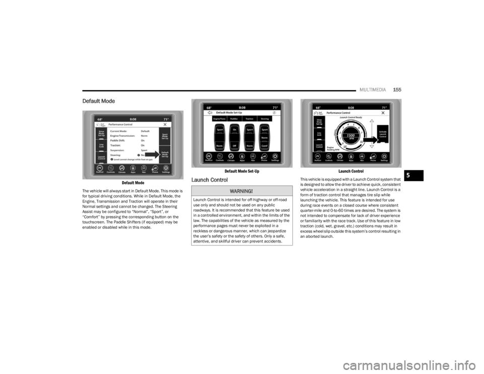
Default Mode
Default Mode
The vehicle will always start in Default Mode. This mode is
for typical driving conditions. While in Default Mode, the
Engine, Transmission and Traction will operate in their
Normal settings and cannot be changed. The Steering
Assist may be configured to “Normal”, “Sport”, or
“Comfort” by pressing the corresponding button on the
touchscreen. The Paddle Shifters (if equipped) may be
enabled or disabled while in this mode.
Default Mode Set-Up
Launch Control
Launch Control
This vehicle is equipped with a Launch Control system that
is designed to allow the driver to achieve quick, consistent
vehicle acceleration in a straight line. Launch Control is a
form of traction control that manages tire slip while
launching the vehicle. This feature is intended for use
during race events on a closed course where consistent
quarter-mile and 0-to-60 times are desired. The system is
not intended to compensate for lack of driver experience
or familiarity with the race track. Use of this feature in low
traction (cold, wet, gravel, etc.) conditions may result in
excess wheel slip outside this system’s control resulting in
an aborted launch.
WARNING!
Launch Control is intended for off-highway or off-road
use only and should not be used on any public
roadways. It is recommended that this feature be used
in a controlled environment, and within the limits of the
law. The capabilities of the vehicle as measured by the
performance pages must never be exploited in a
reckless or dangerous manner, which can jeopardize
the user’s safety or the safety of others. Only a safe,
attentive, and skillful driver can prevent accidents.
5
23_LA_OM_EN_USC_t.book Page 155
Page 158 of 300

156MULTIMEDIA
NOTE:
Launch Control should not be used on public roads.
Always check track conditions and the surrounding
area.
Launch Control is not available for the first 500 miles
(805 km) of the vehicle’s life.
Launch Control should only be used when the engine
and transmission are at operating temperature.
Launch Control is intended to be used on dry, paved
road surfaces only. Use on slippery or loose surfaces
may cause damage to vehicle components and is not
recommended.
Launch Control is not available in ESC Full Off Mode.
Sport Mode
Sport Mode
Sport Mode is a configuration setup for typical enthusiast
driving. The Transmission and Steering are both set to
their Sport settings. The steering wheel Paddle switches
are enabled. Traction Control defaults to Normal. Any of
these four settings may be changed to the driver’s
preferences by pressing the buttons on the touchscreen.
Push the Sport button on the instrument panel switch
bank to put the vehicle in Sport Mode and activate these
settings. The customized settings will only be active when
the Sport button is active.
Sport Mode Set-Up
Possible Performance Control configurations are listed
with accompanying descriptions. The information
contained in the following list can also be accessed from
within the mode Set-Up menus. To access the information,
press the Info button on the touchscreen from the mode
Set-Up menu, and use the Left/Right arrows to toggle
through available descriptions. The title for each system in
the Set-Up menu can be pressed, which provides the
descriptions for each function of that system.
ENGINE/TRANS (IF EQUIPPED WITH
AUTOMATIC TRANSMISSION)
Engine/Trans
SPORT
Press the Sport button on the touchscreen for
improved throttle response and modified shifting for an
enhanced driving experience.
NORMAL
Press the Normal button on the touchscreen for a
balance of throttle response, shift comfort and
economy for normal driving.
23_LA_OM_EN_USC_t.book Page 156
Page 159 of 300
MULTIMEDIA157
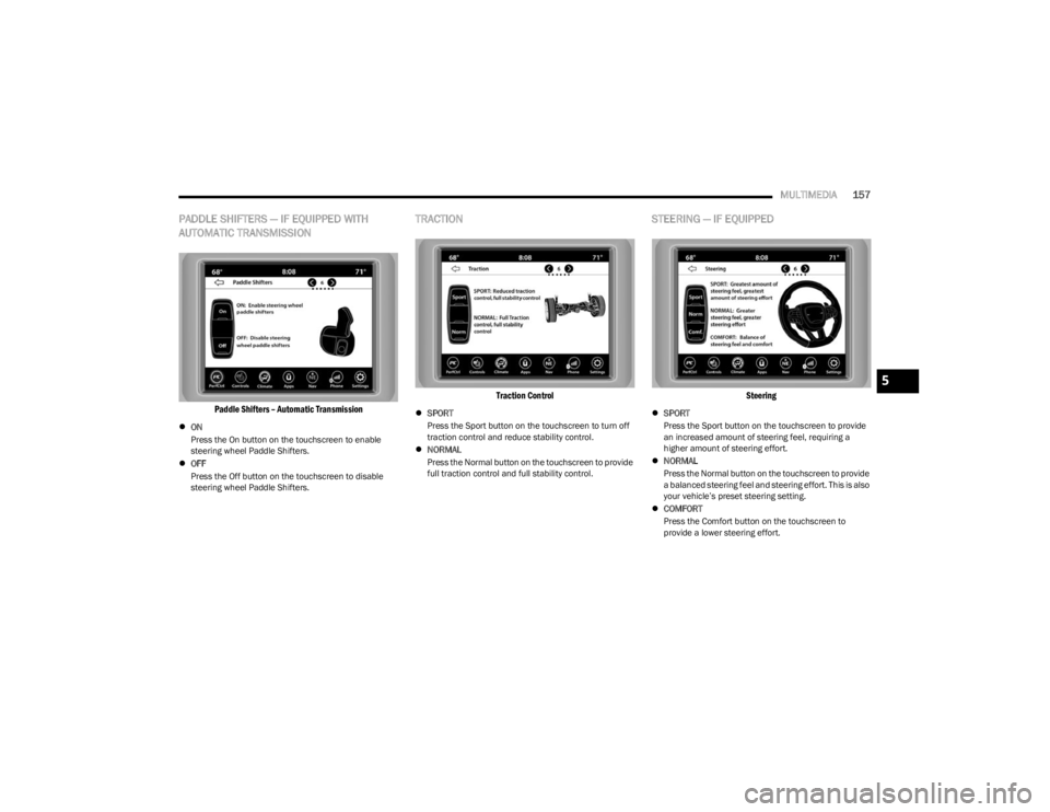
PADDLE SHIFTERS — IF EQUIPPED WITH
AUTOMATIC TRANSMISSION
Paddle Shifters – Automatic Transmission
ON
Press the On button on the touchscreen to enable
steering wheel Paddle Shifters.
OFF
Press the Off button on the touchscreen to disable
steering wheel Paddle Shifters.
TRACTION
Traction Control
SPORT
Press the Sport button on the touchscreen to turn off
traction control and reduce stability control.
NORMAL
Press the Normal button on the touchscreen to provide
full traction control and full stability control.
STEERING — IF EQUIPPED
Steering
SPORT
Press the Sport button on the touchscreen to provide
an increased amount of steering feel, requiring a
higher amount of steering effort.
NORMAL
Press the Normal button on the touchscreen to provide
a balanced steering feel and steering effort. This is also
your vehicle’s preset steering setting.
COMFORT
Press the Comfort button on the touchscreen to
provide a lower steering effort.
5
23_LA_OM_EN_USC_t.book Page 157
Page 165 of 300
SAFETY163
The following conditions must be met in order for HSA to
activate:
The feature must be enabled.
The vehicle must be stopped.
The parking brake must be off.
The driver door must be closed.
The vehicle must be on a sufficient grade.
The gear selection must match vehicle uphill direction
(i.e., vehicle facing uphill is in forward gear; vehicle
backing uphill is in REVERSE gear).
HSA will work in REVERSE gear and all forward gears.
The system will not activate if the transmission is in
PARK or NEUTRAL. For vehicles equipped with a
manual transmission, if the clutch is pressed, HSA will
remain active.Disabling And Enabling HSA
This feature can be turned on or turned off. To change the
current setting, proceed as follows:
If disabling HSA using Uconnect Settings, see
Úpage 107.
Towing With HSA
HSA will also provide assistance to mitigate roll back while
towing a trailer.
Rain Brake Support (RBS)
RBS may improve braking performance in wet conditions.
It will periodically apply a small amount of brake pressure
to remove any water buildup on the front brake rotors. It
functions when the windshield wipers are in LO or HI
speed. When RBS is active, there is no notification to the
driver and no driver interaction is required.
Ready Alert Braking (RAB)
RAB may reduce the time required to reach full braking
during emergency braking situations. It anticipates when
an emergency braking situation may occur by monitoring
how fast the throttle is released by the driver. The
Electronic Brake Controller (EBC) will prepare the brake
system for a panic stop.
Traction Control System (TCS)
The TCS monitors the amount of wheel spin of each of the
driven wheels. If wheel spin is detected, the TCS may apply
brake pressure to the spinning wheel(s) and/or reduce
engine power to provide enhanced acceleration and
stability. A feature of the TCS, Brake Limited Differential
(BLD) functions similarly to a limited slip differential and
controls the wheel spin across a driven axle. If one wheel
on a driven axle is spinning faster than the other, the
system will apply the brake of the spinning wheel. This will
allow more engine power to be applied to the wheel that is
not spinning. BLD may remain enabled even if TCS and
ESC are in reduced modes.WARNING!
There may be situations where the Hill Start Assist
(HSA) will not activate and slight rolling may occur, such
as on minor hills or with a loaded vehicle, or while
pulling a trailer. HSA is not a substitute for active driving
involvement. It is always the driver’s responsibility to be
attentive to distance to other vehicles, people, and
objects, and most importantly brake operation to
ensure safe operation of the vehicle under all road
conditions. Your complete attention is always required
while driving to maintain safe control of your vehicle.
Failure to follow these warnings can result in a collision
or serious personal injury.
WARNING!
If you use a trailer brake controller with your trailer,
the trailer brakes may be activated and deactivated
with the brake switch. If so, there may not be enough
brake pressure to hold both the vehicle and the
trailer on a hill when the brake pedal is released. In
order to avoid rolling down an incline while resuming
acceleration, manually activate the trailer brake or
apply more vehicle brake pressure prior to releasing
the brake pedal.
HSA is not a parking brake. Always apply the parking
brake fully when exiting your vehicle. Also, be certain
to place the transmission in PARK.
Failure to follow these warnings can result in a colli -
sion or serious personal injury.
6
23_LA_OM_EN_USC_t.book Page 163
Page 166 of 300

164SAFETY
AUXILIARY DRIVING SYSTEMS
BLIND SPOT MONITORING (BSM) —
I
F EQUIPPED
BSM uses two radar sensors, located inside the rear
fascia/bumper, to detect highway licensable vehicles
(automobiles, trucks, motorcycles, etc.) that enter the
blind spot zones from the rear/front/side of the vehicle.
Rear Detection Zones
When the vehicle is started, the BSM Warning Light will
momentarily illuminate in both outside rearview mirrors to
let the driver know that the system is operational. Automatic Transmission Vehicles
The BSM system sensors operate when the vehicle is in
any forward gear or NEUTRAL.
Manual Transmission Vehicles
The BSM system sensors operate when the vehicle is in
any gear selector position, except REVERSE.
BSM Warning Light
The BSM detection zone covers approximately one lane
width on both sides of the vehicle 12 ft (3.8 m). The zone
length starts at the outside rearview mirror and extends
approximately 10 ft (3 m) beyond the rear fascia/bumper
of the vehicle. The BSM system monitors the detection
zones on both sides of the vehicle when the vehicle speed
reaches approximately 6 mph (10 km/h) or higher and will
alert the driver of vehicles in these areas.
NOTE:
The BSM system DOES NOT alert the driver about
rapidly approaching vehicles that are outside the
detection zones.
The BSM system detection zone DOES NOT change if
your vehicle is towing a trailer. Therefore, visually verify
the adjacent lane is clear for both your vehicle and
trailer before making a lane change. If the trailer or
other object (i.e., bicycle, sports equipment) extends
beyond the side of your vehicle, this may result in the
BSM Warning Light remaining illuminated the entire
time the vehicle is in a forward gear.
The BSM system may experience dropouts (blinking on
and off) of the side mirror warning indicator lamps
when a motorcycle or any small object remains at the
side of the vehicle for extended periods of time (more
than a couple of seconds).
The area on the rear fascia/bumper where the radar
sensors are located must remain free of snow, ice and
dirt/road contamination so that the BSM system can
function properly. Do not block the area of the rear fascia/
bumper where the radar sensors are located with foreign
objects (bumper stickers, bicycle racks, etc.).
23_LA_OM_EN_USC_t.book Page 164
Page 186 of 300

184SAFETY
(Continued)
Do not drive your vehicle after the air bags have deployed.
If you are involved in another collision, the air bags will not
be in place to protect you.
NOTE:
Air bag covers may not be obvious in the interior trim,
but they will open during air bag deployment.
After any collision, the vehicle should be taken to an
authorized dealer immediately.
Enhanced Accident Response System
In the event of an impact, if the communication network
remains intact, and the power remains intact, depending
on the nature of the event, the Occupant Restraint
Controller (ORC) will determine whether to have the
Enhanced Accident Response System perform the
following functions:
Cut off fuel to the engine (if equipped).
Cut off battery power to the electric motor (if equipped).
Flash hazard lights as long as the battery has power.
Turn on the interior lights, which remain on as long as
the battery has power or for 15 minutes from the inter -
vention of the Enhanced Accident Response System.
Unlock the power door locks. Your vehicle may also be designed to perform any of these
other functions in response to the Enhanced Accident
Response System:
Turn off the Fuel Filter Heater, Turn off the HVAC Blower
Motor, Close the HVAC Circulation Door
Cut off battery power to the:
Engine
Electric Motor (if equipped)
Electric power steering
Brake booster
Electric park brake
Automatic transmission gear selector
Horn
Front wiper
NOTE:After an accident, remember to cycle the ignition to the
STOP (OFF/LOCK) position and remove the key from the
ignition switch to avoid draining the battery. Carefully
check the vehicle for fuel leaks in the engine compartment
and on the ground near the engine compartment and fuel
tank before resetting the system and starting the engine.
If there are no fuel leaks or damage to the vehicle elec -
trical devices (e.g. headlights) after an accident, reset the
system by following the procedure described below. If you
have any doubt, contact an authorized dealer.
Enhanced Accident Response System
Reset Procedure
In order to reset the Enhanced Accident Response System
functions after an event, the ignition switch must be
changed from ignition START or ON/RUN to ignition OFF.
Carefully check the vehicle for fuel leaks in the engine
compartment and on the ground near the engine
compartment and fuel tank before resetting the system
and starting the engine.
After an accident, if the vehicle will not start after
performing the reset procedure, the vehicle must be
towed to an authorized dealer to be inspected and to have
the Enhanced Accident Response System reset.
Maintaining Your Air Bag System
WARNING!
Deployed air bags and seat belt pretensioners cannot
protect you in another collision. Have the air bags, seat
belt pretensioners, and the seat belt retractor
assemblies replaced by an authorized dealer
immediately. Also, have the Occupant Restraint
Controller System serviced as well.
WARNING!
Modifications to any part of the air bag system could
cause it to fail when you need it. You could be injured
if the air bag system is not there to protect you. Do
not modify the components or wiring, including
adding any kind of badges or stickers to the steering
wheel hub trim cover or the upper passenger side of
the instrument panel. Do not modify the front fascia/
bumper, vehicle body structure, or add aftermarket
side steps or running boards.
It is dangerous to try to repair any part of the air bag
system yourself. Be sure to tell anyone who works on
your vehicle that it has an air bag system.
23_LA_OM_EN_USC_t.book Page 184
Page 204 of 300
202IN CASE OF EMERGENCY
(Continued)
Automatic SOS — If Equipped
Automatic SOS is a hands-free safety service that can
immediately connect you with help in the event that your
vehicle’s airbags deploy. Please refer to your provided
radio supplement for complete information.
JACKING AND TIRE CHANGING
Use this QR code to access your digital
experience.PREPARATIONS FOR JACKING
1. Park the vehicle on a firm, level surface as far from
the edge of the roadway as possible. Avoid icy or
slippery areas.
2. Turn on the Hazard Warning Flashers.
3. Apply the parking brake.
4. Place the gear selector into PARK (automatic transmission) or FIRST gear (manual transmission).
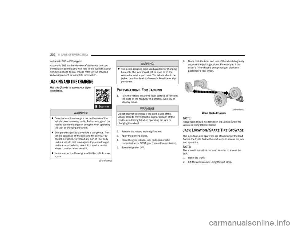
5. Turn the ignition OFF. 6. Block both the front and rear of the wheel diagonally
opposite the jacking position. For example, if the
driver’s front wheel is being changed, block the
passenger’s rear wheel.
Wheel Blocked Example
NOTE:Passengers should not remain in the vehicle when the
vehicle is being lifted or raised.
JACK LOCATION/SPARE TIRE STOWAGE
The jack, tools and spare tire are stowed under the load
floor in the trunk. Follow the next steps to access the jack
and spare tire.
NOTE:The spare tire must be removed in order to access the
jack.
1. Open the trunk.
2. Lift the access cover using the pull strap.
WARNING!
Do not attempt to change a tire on the side of the
vehicle close to moving traffic. Pull far enough off the
road to avoid the danger of being hit when operating
the jack or changing the wheel.
Being under a jacked-up vehicle is dangerous. The
vehicle could slip off the jack and fall on you. You
could be crushed. Never put any part of your body
under a vehicle that is on a jack. If you need to get
under a raised vehicle, take it to a service center
where it can be raised on a lift.
Never start or run the engine while the vehicle is on
a jack.
The jack is designed to be used as a tool for changing
tires only. The jack should not be used to lift the
vehicle for service purposes. The vehicle should be
jacked on a firm level surface only. Avoid ice or slip -
pery areas.
WARNING!
Do not attempt to change a tire on the side of the
vehicle close to moving traffic, pull far enough off the
road to avoid being hit when operating the jack or
changing the wheel.
WARNING!
23_LA_OM_EN_USC_t.book Page 202
Page 205 of 300
IN CASE OF EMERGENCY203
(Continued)
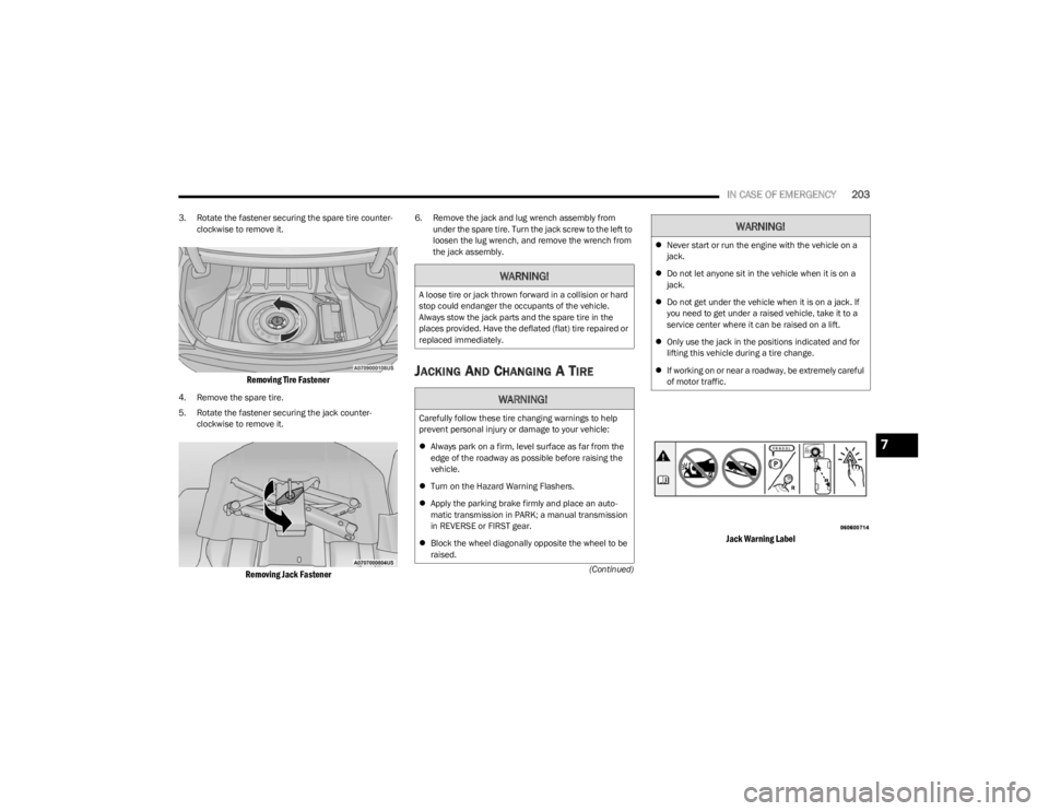
3. Rotate the fastener securing the spare tire counter
-
clockwise to remove it.
Removing Tire Fastener
4. Remove the spare tire.
5. Rotate the fastener securing the jack counter -
clockwise to remove it.
Removing Jack Fastener
6. Remove the jack and lug wrench assembly from under the spare tire. Turn the jack screw to the left to
loosen the lug wrench, and remove the wrench from
the jack assembly.
JACKING AND CHANGING A TIRE
Jack Warning Label
WARNING!
A loose tire or jack thrown forward in a collision or hard
stop could endanger the occupants of the vehicle.
Always stow the jack parts and the spare tire in the
places provided. Have the deflated (flat) tire repaired or
replaced immediately.
WARNING!
Carefully follow these tire changing warnings to help
prevent personal injury or damage to your vehicle:
Always park on a firm, level surface as far from the
edge of the roadway as possible before raising the
vehicle.
Turn on the Hazard Warning Flashers.
Apply the parking brake firmly and place an auto -
matic transmission in PARK; a manual transmission
in REVERSE or FIRST gear.
Block the wheel diagonally opposite the wheel to be
raised.
Never start or run the engine with the vehicle on a
jack.
Do not let anyone sit in the vehicle when it is on a
jack.
Do not get under the vehicle when it is on a jack. If
you need to get under a raised vehicle, take it to a
service center where it can be raised on a lift.
Only use the jack in the positions indicated and for
lifting this vehicle during a tire change.
If working on or near a roadway, be extremely careful
of motor traffic.
WARNING!
7
23_LA_OM_EN_USC_t.book Page 203