2023 DODGE CHALLENGER transmission
[x] Cancel search: transmissionPage 102 of 300

100STARTING AND OPERATING
TRAILER HITCH CLASSIFICATION
The following chart provides the industry standard for the maximum trailer weight a given trailer hitch class can tow and should be used to assist you in selecting the correct trailer hitch
for your intended towing condition.
TRAILER TOWING WEIGHTS (MAXIMUM TRAILER WEIGHT RATINGS)
Trailer towing with the 5.7L manual transmission, 6.4L and 6.2L Supercharged engine is not recommended.
Trailer Hitch Classification Definitions
Class Max. Trailer Hitch Industry Standards
Class I - Light Duty 2,000 lb (907 kg)
Class II - Medium Duty 3,500 lb (1,587 kg)
Class III - Heavy Duty 6,000 lb (2,722 kg)
Class IV - Extra Heavy Duty 10,000 lb (4,535 kg)
Refer to the “Trailer Towing Weights (Maximum Trailer Weight Ratings)” chart for the Maximum Gross Trailer Weight (GTW) towable for your given drivetrain.
All trailer hitches should be professionally installed on your vehicle.
Engine/Transmission Frontal AreaMaximum GTWMaximum Trailer TW
3.6L Automatic 12 sq ft (1.11 sq m)1,000 lb (454 kg) 100 lb (45 kg)
5.7L Automatic 12 sq ft (1.11 sq m)1,000 lb (454 kg) 100 lb (45 kg)
Refer to local laws for maximum trailer towing speeds.
23_LA_OM_EN_USC_t.book Page 100
Page 103 of 300

STARTING AND OPERATING101
(Continued)
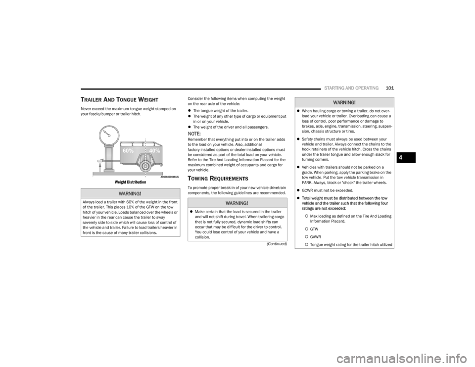
TRAILER AND TONGUE WEIGHT
Never exceed the maximum tongue weight stamped on
your fascia/bumper or trailer hitch.
Weight Distribution
Consider the following items when computing the weight
on the rear axle of the vehicle:
The tongue weight of the trailer.
The weight of any other type of cargo or equipment put
in or on your vehicle.
The weight of the driver and all passengers.
NOTE:Remember that everything put into or on the trailer adds
to the load on your vehicle. Also, additional
factory-installed options or dealer-installed options must
be considered as part of the total load on your vehicle.
Refer to the Tire And Loading Information Placard for the
maximum combined weight of occupants and cargo for
your vehicle.
TOWING REQUIREMENTS
To promote proper break-in of your new vehicle drivetrain
components, the following guidelines are recommended.
WARNING!
Always load a trailer with 60% of the weight in the front
of the trailer. This places 10% of the GTW on the tow
hitch of your vehicle. Loads balanced over the wheels or
heavier in the rear can cause the trailer to sway
severely side to side which will cause loss of control of
the vehicle and trailer. Failure to load trailers heavier in
front is the cause of many trailer collisions.WARNING!
Make certain that the load is secured in the trailer
and will not shift during travel. When trailering cargo
that is not fully secured, dynamic load shifts can
occur that may be difficult for the driver to control.
You could lose control of your vehicle and have a
collision.
When hauling cargo or towing a trailer, do not over -
load your vehicle or trailer. Overloading can cause a
loss of control, poor performance or damage to
brakes, axle, engine, transmission, steering, suspen -
sion, chassis structure or tires.
Safety chains must always be used between your
vehicle and trailer. Always connect the chains to the
hook retainers of the vehicle hitch. Cross the chains
under the trailer tongue and allow enough slack for
turning corners.
Vehicles with trailers should not be parked on a
grade. When parking, apply the parking brake on the
tow vehicle. Put the tow vehicle transmission in
PARK. Always, block or "chock" the trailer wheels.
GCWR must not be exceeded.
Total weight must be distributed between the tow
vehicle and the trailer such that the following four
ratings are not exceeded :
Max loading as defined on the Tire And Loading
Information Placard.
GTW
GAWR
Tongue weight rating for the trailer hitch utilized
WARNING!
4
23_LA_OM_EN_USC_t.book Page 101
Page 105 of 300

STARTING AND OPERATING103
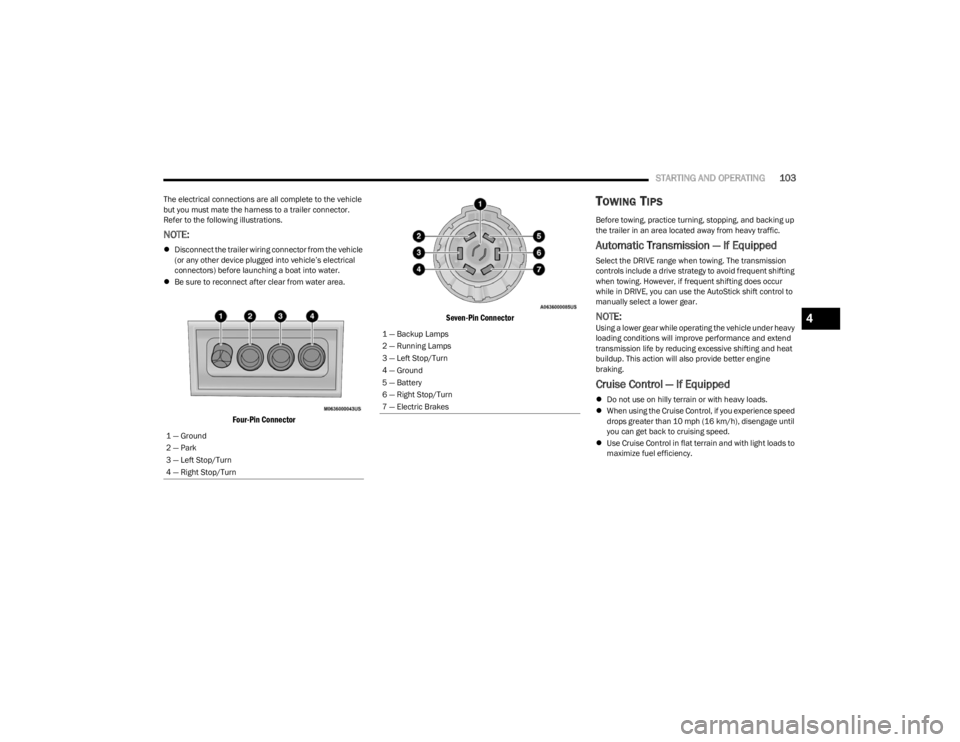
The electrical connections are all complete to the vehicle
but you must mate the harness to a trailer connector.
Refer to the following illustrations.
NOTE:
Disconnect the trailer wiring connector from the vehicle
(or any other device plugged into vehicle’s electrical
connectors) before launching a boat into water.
Be sure to reconnect after clear from water area.
Four-Pin Connector Seven-Pin Connector
TOWING TIPS
Before towing, practice turning, stopping, and backing up
the trailer in an area located away from heavy traffic.
Automatic Transmission — If Equipped
Select the DRIVE range when towing. The transmission
controls include a drive strategy to avoid frequent shifting
when towing. However, if frequent shifting does occur
while in DRIVE, you can use the AutoStick shift control to
manually select a lower gear.
NOTE:Using a lower gear while operating the vehicle under heavy
loading conditions will improve performance and extend
transmission life by reducing excessive shifting and heat
buildup. This action will also provide better engine
braking.
Cruise Control — If Equipped
Do not use on hilly terrain or with heavy loads.
When using the Cruise Control, if you experience speed
drops greater than 10 mph (16 km/h), disengage until
you can get back to cruising speed.
Use Cruise Control in flat terrain and with light loads to
maximize fuel efficiency.
1 — Ground
2 — Park
3 — Left Stop/Turn
4 — Right Stop/Turn
1 — Backup Lamps
2 — Running Lamps
3 — Left Stop/Turn
4 — Ground
5 — Battery
6 — Right Stop/Turn
7 — Electric Brakes
4
23_LA_OM_EN_USC_t.book Page 103
Page 106 of 300

104STARTING AND OPERATING
AutoStick
When using the AutoStick shift control, select the
highest gear that allows for adequate performance and
avoids frequent downshifts. For example, choose “5” if
the desired speed can be maintained. Choose “4” or
“3” if needed to maintain the desired speed.
To prevent excess heat generation, avoid continuous
driving at high RPM. Reduce vehicle speed as neces -
sary to avoid extended driving at high RPM. Return to a
higher gear or vehicle speed when grade and road
conditions allow.
RECREATIONAL TOWING
(BEHIND MOTORHOME)
Recreational towing (with all four wheels on the ground, or
using a tow dolly) is NOT ALLOWED. The only acceptable
method for towing this vehicle (behind another vehicle) is
on a vehicle trailer with all four wheels OFF the ground.
DRIVING TIPS
DRIVING ON SLIPPERY SURFACES
Information in this section will aid in safe controlled
launches in adverse conditions.
Acceleration
Rapid acceleration on snow covered, wet, or other slippery
surfaces may cause the driving wheels to pull erratically to
the right or left. This phenomenon occurs when there is a
difference in the surface traction under the rear (driving)
wheels.
Traction
When driving on wet or slushy roads, it is possible for a
wedge of water to build up between the tire and road
surface. This is known as hydroplaning and may cause
partial or complete loss of vehicle control and stopping
ability. To reduce this possibility, the following precautions
should be observed:
Slow down during rainstorms or when the roads are
slushy.
Slow down if the road has standing water or puddles.
Replace tires when tread wear indicators first become
visible.
Keep tires properly inflated.
Maintain sufficient distance between your vehicle and
the vehicle in front of you to avoid a collision in a
sudden stop.
Your vehicle may be equipped with a Limited Slip
Differential (LSD) that reduces, but does not eliminate, the
amount of wheel slip across a given axle for improved
handling.
CAUTION!
Towing this vehicle in violation of the above
requirements can cause severe engine, transmission
and/or transfer case damage. Damage from improper
towing is not covered under the New Vehicle Limited
Warranty.
WARNING!
Rapid acceleration on slippery surfaces is dangerous.
Unequal traction can cause sudden pulling of the rear
wheels. You could lose control of the vehicle and
possibly have a collision. Accelerate slowly and carefully
whenever there is likely to be poor traction (ice, snow,
wet, mud, loose sand, etc.).
23_LA_OM_EN_USC_t.book Page 104
Page 151 of 300

MULTIMEDIA149
3. After selecting a widget location, select the gauge to
display:
Gauge: Oil Temp
Gauge: Oil Pressure
Gauge: Coolant Temp
Gauge: Battery Voltage
Gauge: Trans Temp — If Equipped with an Auto -
matic Transmission
Gauge: Boost Pressure — If Equipped
Gauge: Air/Fuel Ratio — If Equipped
Gauge: I/C Coolant Temp — If Equipped
Gauge: Intake Air Temp
Gauge: Engine Torque
Gauge: Engine Power
Gauge: G-Force
Gauge: Steering Angle
Gauge: Current Gear
Gauge: Current Speed
Timer: 0–60 mph (0–100 km/h)
Timer: 0–100 mph (0–160 km/h)
Timer: 60 ft (20 m)
Timer: 330 ft (100 m)
Timer: 1/8 Mile (200 m)
Timer: 1000 ft (300 m)
Timer: 1/4 Mile (400 m)
Timer: Braking Distance
Timer: Reaction Time
Historical Data
The Historical Data feature allows you to view information
about your vehicle such as the VIN, miles on the odometer,
longitude and latitude coordinates, and more.
To activate the Historical Data feature on your
touchscreen, follow these steps:
1. Select the Home page tab within Performance Pages. Then, press the settings icon (gear icon) in
the upper right hand corner of the touchscreen.
Home Page Settings
2. Towards the bottom of the screen, a checkbox will appear next to “Include historical data in
screenshot.” Click the box to signify that this feature
will be on.
Historical Data
NOTE:Once the checkbox is selected, the bottom bar of the
screen will be replaced with the historical data from your
vehicle present at the time the screenshot icon was
pressed.
5
23_LA_OM_EN_USC_t.book Page 149
Page 154 of 300

152MULTIMEDIA
GAUGES
Performance Pages — Gauges
When selected, this screen displays the following values:
Oil Temperature
Shows the actual oil temperature.
Oil Pressure
Shows the actual oil pressure.
Coolant Temperature
Shows the actual coolant temperature.
Battery Voltage
Shows actual battery voltage.
Trans Oil Temp — If Equipped with an Automatic
Transmission
Shows actual transmission oil temperature.
Boost Pressure — If Equipped
Shows actual boost pressure.
Air Fuel Ratio — If Equipped
Shows current air fuel ratio.
I/C Coolant Temp — If Equipped
Shows actual I/C Coolant temperature.
Intake Air Temp
Shows actual air intake temperature.
If a gauge is selected, the Gauge Detail View page will
appear on the screen. This page shows gauge values for
the previous two minutes on the selected gauge.
Pressing the Left and Right arrows will cycle through the
details for each of the gauges. Pressing the minimize
button above the graph will return to the gauge menu.
Gauge Detail View Page
G-FORCE
Performance Pages — G-Force
When selected, this screen displays all four G-Force values
as well as steering angle.
When G-Force is selected, the following features will be
available:
Vehicle Speed:
Measures the current speed of the vehicle in either
mph or km/h, starting at zero with no maximum value.
Front G-Force:
Measures the peak braking force on the front of the
vehicle.
23_LA_OM_EN_USC_t.book Page 152
Page 155 of 300

MULTIMEDIA153
Right G-Force:
Measures the peak force on the right side of the
vehicle.
Left G-Force:
Measures the peak force on the left side of the vehicle.
Rear G-Force:
Measures the peak acceleration force on the rear of
the vehicle.
NOTE:Front, Right, Left, and Rear G-Forces are all peak values.
These readings can be reset by clearing peak G-Force on
the instrument cluster.
Steering Wheel Angle
Steering Wheel Angle utilizes the steering angle sensor
to measure the degree of the steering wheel relative to
zero (straight ahead) reference angle. The zero degree
reference angle measurement indicates a steering
wheel straight ahead position.
The friction circle display shows instantaneous G-Force as
a highlight and previous G-Force as dots within the circle.
The system records previous G-Force for three minutes. If
there are multiple samples at a given point, the color of
the dot will darken from blue to red. Vectors more frequent
will show in red; infrequent vectors will show in blue.
ENGINE
Performance Pages — Engine
When selected, this screen displays the following values:
Vehicle Speed
Shows the actual vehicle speed.
Engine Power
Shows the instantaneous power.
Engine Torque
Shows the instantaneous torque.
Oil Pressure (6.4L Only) — If Equipped
Shows the actual engine oil pressure.
Boost Pressure (6.2L Only) — If Equipped
Shows the actual boost pressure.
Gear (Automatic Transmission Only)
Shows the current (or pending) operating gear of the
vehicle.
DYNAMOMETER (DYNO)
Performance Pages — Dyno
The system will start drawing graphs for Power and Torque
(top chart) and Engine Speed (bottom chart). The graph
will fill to the right side of the page (based on History time
selected). Once the right side of the page is reached, the
graph will scroll with the right side always being the most
recent recorded sample.
5
23_LA_OM_EN_USC_t.book Page 153
Page 156 of 300

154MULTIMEDIA
The following options can be selected:
Pressing the STOP button will freeze the graph.
Selecting Play will clear the graph and restart the
process over.
Press the + or - buttons to change the history of the
graph. The selectable options are “30”, “60”, “90”, and
“120” seconds. The graph will expand or constrict
depending on the setting selected.
Select the “Gear” display setting to turn the graph gear
markers on and off for automatic transmission vehicles
only.
NOTE:The Gear on/off feature will only display if your vehicle is
equipped with an Automatic Transmission.
DODGE DRIVE MODES — IF EQUIPPED
PERFORMANCE CONTROL —
I
F EQUIPPED
Your vehicle may be equipped with a Performance Control
feature which allows for coordinating the operation of
various vehicle systems depending upon the type of
driving behavior desired. The Performance Control feature
is controlled through the Uconnect system and may be
accessed by performing any of the following:
Pushing the Super Track Pack button on the instru -
ment panel switch bank.
Selecting “Performance Control” from the Apps menu.
Selecting “Performance Control” from within the
Performance Pages menu. You will be able to enable, disable, and customize the
functionality of the Launch Control and Performance
Control Set-Up features within Performance Control.
To access information about the functionality of these
features through the Uconnect system, press the Info
button on the touchscreen.
NOTE:Dodge vehicles equipped with a 6.4L engine, except for
R/T Scat Pack 1320 6.4L non-widebody vehicles, will use
SRT Drive Modes rather than the Dodge Performance
Control Pages. Please refer to the following sections for
further information on the SRT Drive Modes.
Drive Mode Set-Up
Performance Control Set-Up
Pressing the Drive Mode Set-Up button on the
touchscreen within the Performance Control screen
indicates the real-time status of the various systems.
Pressing the Sport Mode Set-Up, Drag Mode Set-Up
(1320 only), or Default Mode Set-Up buttons on the
touchscreen allows the driver to configure their individual
performance control and see how those configurations
affect the performance of the vehicle.
NOTE:Not all of the options listed in this manual are available on
every vehicle. Here is a chart with all available Perfor
-
mance Control vehicle configurations:
Available Mode Configurations
Refer to the Sport and Default Modes for their detailed
operation.
NOTE:These settings will remain in effect when using the Launch
Control feature.
Engine If Manual Transmission
Engine/Transmission If Auto Transmission
Steering X
Paddle Shifters If Auto Transmission
Traction Control X
Suspension If Adaptive Suspension
23_LA_OM_EN_USC_t.book Page 154