2023 DODGE CHALLENGER radio
[x] Cancel search: radioPage 38 of 300

36GETTING TO KNOW YOUR VEHICLE
POWER MIRRORS
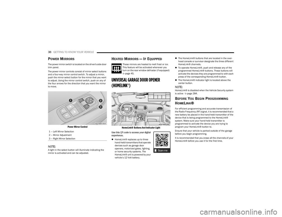
The power mirror switch is located on the driver's side door
trim panel.
The power mirror controls consist of mirror select buttons
and a four-way mirror control switch. To adjust a mirror,
push the mirror select button for the mirror that you want
to adjust. Using the mirror control switch, push on any of
the four arrows for the direction that you want the mirror
to move.
Power Mirror Control
NOTE:A light in the select button will illuminate indicating the
mirror is activated and can be adjusted.
HEATED MIRRORS — IF EQUIPPED
These mirrors are heated to melt frost or ice.
This feature will be activated whenever you
turn on the rear window defroster (if equipped)
Úpage 45.
UNIVERSAL GARAGE DOOR OPENER
(HOMELINK®)
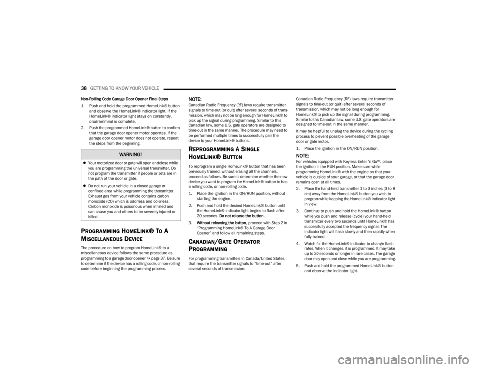
HomeLink® Buttons And Indicator Light
Use this QR code to access your digital
experience.
HomeLink® replaces up to three
hand-held transmitters that operate
devices such as garage door
openers, motorized gates, lighting,
or home security systems. The
HomeLink® unit is powered by your
vehicle’s 12 Volt battery.
The HomeLink® buttons that are located in the over -
head console or sunvisor designate the three different
HomeLink® channels.
To operate HomeLink®, push and release any of the
programmed HomeLink® buttons. These buttons will
activate the devices they are programmed to with each
press of the corresponding HomeLink® button.
The HomeLink® indicator light is located above the
center button.
NOTE:HomeLink® is disabled when the Vehicle Security system
is active Úpage 284.
BEFORE YOU BEGIN PROGRAMMING
H
OMELINK®
For efficient programming and accurate transmission of
the Radio Frequency (RF) signal, it is recommended that a
new battery be placed in the hand-held transmitter of the
device that is being programmed to the HomeLink®
system. Make sure your hand-held transmitter is
programmed to activate the device you are trying to
program your HomeLink® button to.
Ensure that your vehicle is parked outside of the garage
before you begin programming.
It is recommended that you erase all the channels of your
HomeLink® before you use it for the first time.
1 — Left Mirror Selection
2 — Mirror Adjustment
3 — Right Mirror Selection
23_LA_OM_EN_USC_t.book Page 36
Page 40 of 300

38GETTING TO KNOW YOUR VEHICLE
Non-Rolling Code Garage Door Opener Final Steps
1. Push and hold the programmed HomeLink® button
and observe the HomeLink® indicator light. If the
HomeLink® indicator light stays on constantly,
programming is complete.
2. Push the programmed HomeLink® button to confirm that the garage door opener motor operates. If the
garage door opener motor does not operate, repeat
the steps from the beginning.
PROGRAMMING HOMELINK® TO A
M
ISCELLANEOUS DEVICE
The procedure on how to program HomeLink® to a
miscellaneous device follows the same procedure as
programming to a garage door opener
Úpage 37. Be sure
to determine if the device has a rolling code, or non-rolling
code before beginning the programming process.
NOTE:Canadian Radio Frequency (RF) laws require transmitter
signals to time-out (or quit) after several seconds of trans -
mission, which may not be long enough for HomeLink® to
pick up the signal during programming. Similar to this
Canadian law, some U.S. gate operators are designed to
time-out in the same manner. The procedure may need to
be performed multiple times to successfully pair the
device to your HomeLink® buttons.
REPROGRAMMING A SINGLE
H
OMELINK® BUTTON
To reprogram a single HomeLink® button that has been
previously trained, without erasing all the channels,
proceed as follows. Be sure to determine whether the new
device you want to program the HomeLink® button to has
a rolling code, or non-rolling code.
1. Place the ignition in the ON/RUN position, without
starting the engine.
2. Push and hold the desired HomeLink® button until the HomeLink® indicator light begins to flash after
20 seconds. Do not release the button.
3. Without releasing the button , proceed with Step 2 in
“Programming HomeLink® To A Garage Door
Opener” and follow all remaining steps.
CANADIAN/GATE OPERATOR
P
ROGRAMMING
For programming transmitters in Canada/United States
that require the transmitter signals to “time-out” after
several seconds of transmission: Canadian Radio Frequency (RF) laws require transmitter
signals to time-out (or quit) after several seconds of
transmission, which may not be long enough for
HomeLink® to pick up the signal during programming.
Similar to this Canadian law, some U.S. gate operators are
designed to time-out in the same manner.
It may be helpful to unplug the device during the cycling
process to prevent possible overheating of the garage
door or gate motor.
1. Place the ignition in the ON/RUN position.
NOTE:For vehicles equipped with Keyless Enter ‘n Go™, place
the ignition in the RUN position. Make sure while
programming HomeLink® with the engine on that your
vehicle is outside of your garage, or that the garage door
remains open at all times.
2. Place the hand-held transmitter 1 to 3 inches (3 to 8
cm) away from the HomeLink® button you wish to
program while keeping the HomeLink® indicator light
in view.
3. Continue to push and hold the HomeLink® button while you push and release (cycle) your hand-held
transmitter every two seconds until HomeLink® has
successfully accepted the frequency signal. The
indicator light will flash slowly and then rapidly when
fully trained.
4. Watch for the HomeLink® indicator to change flash rates. When it changes, it is programmed. It may take
up to 30 seconds or longer in rare cases. The garage
door may open and close while you are programming.
5. Push and hold the programmed HomeLink® button and observe the indicator light.
WARNING!
Your motorized door or gate will open and close while
you are programming the universal transmitter. Do
not program the transmitter if people or pets are in
the path of the door or gate.
Do not run your vehicle in a closed garage or
confined area while programming the transmitter.
Exhaust gas from your vehicle contains carbon
monoxide (CO) which is odorless and colorless.
Carbon monoxide is poisonous when inhaled and
can cause you and others to be severely injured or
killed.
23_LA_OM_EN_USC_t.book Page 38
Page 45 of 300

GETTING TO KNOW YOUR VEHICLE43
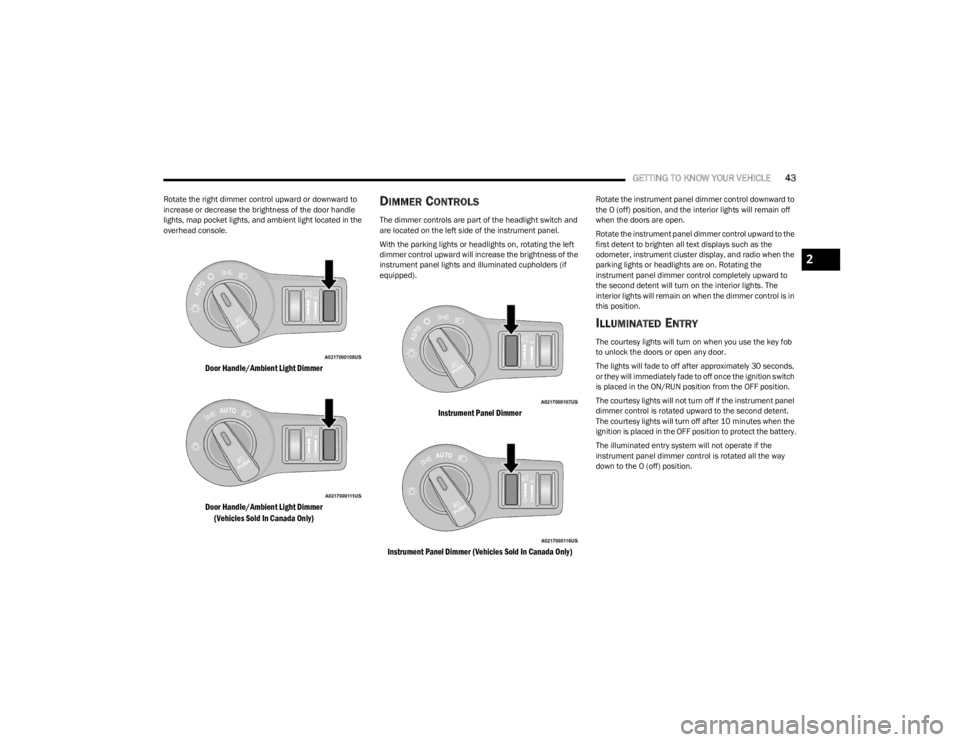
Rotate the right dimmer control upward or downward to
increase or decrease the brightness of the door handle
lights, map pocket lights, and ambient light located in the
overhead console.
Door Handle/Ambient Light Dimmer
Door Handle/Ambient Light Dimmer
(Vehicles Sold In Canada Only)
DIMMER CONTROLS
The dimmer controls are part of the headlight switch and
are located on the left side of the instrument panel.
With the parking lights or headlights on, rotating the left
dimmer control upward will increase the brightness of the
instrument panel lights and illuminated cupholders (if
equipped).
Instrument Panel Dimmer
Instrument Panel Dimmer (Vehicles Sold In Canada Only)
Rotate the instrument panel dimmer control downward to
the O (off) position, and the interior lights will remain off
when the doors are open.
Rotate the instrument panel dimmer control upward to the
first detent to brighten all text displays such as the
odometer, instrument cluster display, and radio when the
parking lights or headlights are on. Rotating the
instrument panel dimmer control completely upward to
the second detent will turn on the interior lights. The
interior lights will remain on when the dimmer control is in
this position.
ILLUMINATED ENTRY
The courtesy lights will turn on when you use the key fob
to unlock the doors or open any door.
The lights will fade to off after approximately 30 seconds,
or they will immediately fade to off once the ignition switch
is placed in the ON/RUN position from the OFF position.
The courtesy lights will not turn off if the instrument panel
dimmer control is rotated upward to the second detent.
The courtesy lights will turn off after 10 minutes when the
ignition is placed in the OFF position to protect the battery.
The illuminated entry system will not operate if the
instrument panel dimmer control is rotated all the way
down to the O (off) position.
2
23_LA_OM_EN_USC_t.book Page 43
Page 47 of 300

GETTING TO KNOW YOUR VEHICLE45
RAIN SENSING WIPERS — IF EQUIPPED
This feature senses rain or snowfall on the windshield and
automatically activates the wipers. Rotate the end of the
multifunction lever to one of four settings to activate this
feature.
The sensitivity of the system can be adjusted with the
multifunction lever. Wiper delay position 1 is the least
sensitive, and wiper delay position 4 is the most sensitive.
Wiper delay position three should be used for normal rain
conditions.
NOTE:
The Rain Sensing feature will not operate when the
wiper switch is in the low or high-speed position.
The Rain Sensing feature may not function properly
when ice, or dried salt water is present on the
windshield.
Use of products containing wax or silicone may reduce
Rain Sensing performance.
The Rain Sensing feature can be turned on and off
using the Uconnect system
Úpage 107.
The Rain Sensing system has protection features for the
wiper blades and arms, and will not operate under the
following conditions:
Low Ambient Temperature — When the ignition is first
placed in the ON position, the Rain Sensing system will
not operate until the wiper switch is moved, vehicle
speed is greater than 0 mph (0 km/h), or the outside
temperature is greater than 32°F (0°C).
Transmission In NEUTRAL Position — When the ignition
is ON, and the transmission is in the NEUTRAL position,
the Rain Sensing system will not operate until the wiper
switch is moved, vehicle speed is greater than 3 mph
(5 km/h), or the gear selector is moved out of the
NEUTRAL position.
Remote Start Mode Inhibit — On vehicles equipped with
the Remote Start system, Rain Sensing wipers are not
operational when the vehicle is in the Remote Start
mode.
CLIMATE CONTROLS
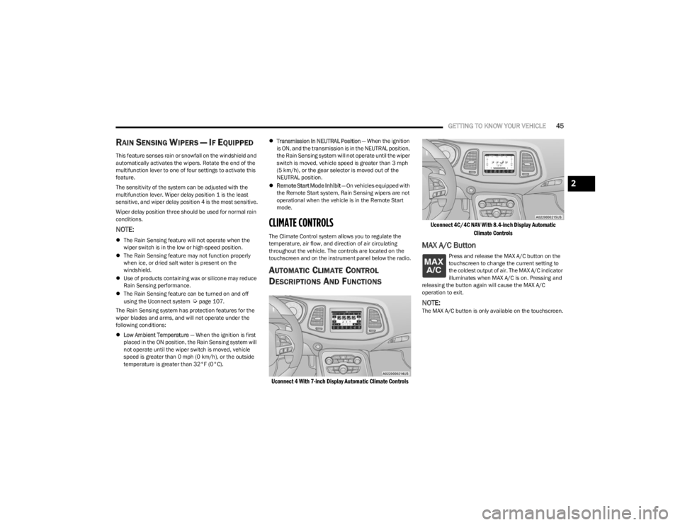
The Climate Control system allows you to regulate the
temperature, air flow, and direction of air circulating
throughout the vehicle. The controls are located on the
touchscreen and on the instrument panel below the radio.
AUTOMATIC CLIMATE CONTROL
D
ESCRIPTIONS AND FUNCTIONS
Uconnect 4 With 7-inch Display Automatic Climate Controls Uconnect 4C/4C NAV With 8.4-inch Display Automatic
Climate Controls
MAX A/C Button
Press and release the MAX A/C button on the
touchscreen to change the current setting to
the coldest output of air. The MAX A/C indicator
illuminates when MAX A/C is on. Pressing and
releasing the button again will cause the MAX A/C
operation to exit.
NOTE:The MAX A/C button is only available on the touchscreen.
2
23_LA_OM_EN_USC_t.book Page 45
Page 64 of 300

62GETTING TO KNOW YOUR INSTRUMENT PANEL
Audio
This menu displays the Audio information of the currently
playing audio source (e.g. FM radio).
Messages
This feature shows the number of stored warning
messages, if any. Pushing the right or left arrow
button will allow you to scroll through the stored
messages.
Screen Setup
Push and release the up or down arrow button until
the Screen Setup Menu displays in the instrument cluster
display. Push and release the OK button to enter the
submenus. The Screen Setup feature allows you to
change what information is displayed in the instrument
cluster as well as the location that information is
displayed.
NOTE:Based upon equipment options and current vehicle
status, some of the features may not be available.
Current Gear
On
Off
Odometer
Show
Hide Gear Display
Full
Single
Restore Defaults
Restore
Cancel
BATTERY SAVER ON/BATTERY SAVER
M
ODE MESSAGE — ELECTRICAL LOAD
R
EDUCTION ACTIONS — IF EQUIPPED
This vehicle is equipped with an Intelligent Battery Sensor
(IBS) to perform additional monitoring of the electrical
system and status of the vehicle battery.
In cases when the IBS detects charging system failure, or
the vehicle battery conditions are deteriorating, electrical
load reduction actions will take place to extend the driving
time and distance of the vehicle. This is done by reducing
power to or turning off non-essential electrical loads.
Load reduction is only active when the engine is running.
It will display a message if there is a risk of battery
depletion to the point where the vehicle may stall due to
lack of electrical supply, or will not restart after the current
drive cycle.
When load reduction is activated, the message “Battery
Saver On” or “Battery Saver Mode” will appear in the
instrument cluster.
These messages indicate the vehicle battery has a low
state of charge and continues to lose electrical charge at
a rate that the charging system cannot sustain.
Upper Left
Compass -
If Equipped Outside Temp Time
Range to Empty Average (MPG,
L/100 km, or
km/L)Current (MPG,
L/100 km, or
km/L)
Trip A Distance Trip B Distance None
Upper Right
Compass -
If Equipped Outside Temp Time
Range to Empty Average (MPG,
L/100 km, or
km/L)Current (MPG,
L/100 km, or
km/L)
Trip A Distance Trip B Distance None
Center
Menu Title Compass -
If EquippedOutside Temp
Time Range to EmptyAverage (MPG,
L/100 km, or
km/L)
Current (MPG,
L/100 km, or
km/L) Trip A Distance Trip B Distance
Audio
Information Digital Speed None
23_LA_OM_EN_USC_t.book Page 62
Page 65 of 300

GETTING TO KNOW YOUR INSTRUMENT PANEL63
NOTE:
The charging system is independent from load reduc -
tion. The charging system performs a diagnostic on the
charging system continuously.
If the Battery Charge Warning Light is on it may indicate
a problem with the charging system
Úpage 64.
The electrical loads that may be switched off (if equipped),
and vehicle functions which can be affected by load
reduction:
Heated Seat/Vented Seats/Heated Wheel
Heated/Cooled Cup Holders — If Equipped
Rear Defroster And Heated Mirrors
HVAC System
115 Volts AC Power Inverter System
Audio and Telematics System
Loss of the battery charge may indicate one or more of the
following conditions:
The charging system cannot deliver enough electrical
power to the vehicle system because the electrical
loads are larger than the capability of the charging
system. The charging system is still functioning prop -
erly.
Turning on all possible vehicle electrical loads
(e.g. HVAC to max settings, exterior and interior lights,
overloaded power outlets +12 Volts, 115 Volts AC, USB
ports) during certain driving conditions (city driving,
towing, frequent stopping).
Installing options like additional lights, upfitter elec -
trical accessories, audio systems, alarms and similar
devices.
Unusual driving cycles (short trips separated by long
parking periods).
The vehicle was parked for an extended period of time
(weeks, months).
The battery was recently replaced and was not charged
completely.
The battery was discharged by an electrical load left on
when the vehicle was parked.
The battery was used for an extended period with the
engine not running to supply radio, lights, chargers,
+12 Volts portable appliances like vacuum cleaners,
game consoles and similar devices.
What to do when an electrical load reduction action
message is present (“Battery Saver On” or “Battery Saver
Mode”)
During a trip:
Reduce power to unnecessary loads if possible:
Turn off redundant lights (interior or exterior)
Check what may be plugged in to power outlets
+12 Volts, 115 Volts AC, USB ports
Check HVAC settings (blower, temperature)
Check the audio settings (volume)
After a trip:
Check if any aftermarket equipment was installed
(additional lights, upfitter electrical accessories, audio
systems, alarms) and review specifications if any (load
and Ignition Off Draw currents).
Evaluate the latest driving cycles (distance, driving
time and parking time).
The vehicle should have service performed if the
message is still present during consecutive trips and
the evaluation of the vehicle and driving pattern did not
help to identify the cause.
WARNING LIGHTS AND MESSAGES
The warning/indicator lights will illuminate in the
instrument panel together with a dedicated message
and/or acoustic signal when applicable. These indications
are indicative and precautionary and as such must not be
considered as exhaustive and/or alternative to the
information contained in the Owner’s Manual, which you
are advised to read carefully in all cases. Always refer to
the information in this chapter in the event of a failure
indication. All active telltales will display first if applicable.
The system check menu may appear different based upon
equipment options and current vehicle status. Some
telltales are optional and may not appear.
RED WARNING LIGHTS
Air Bag Warning Light
This warning light will illuminate to indicate a
fault with the air bag, and will turn on for four to
eight seconds as a bulb check when the
ignition is placed in the ON/RUN or ACC/ON/
RUN position. This light will illuminate with a single chime
when a fault with the air bag has been detected, it will stay
on until the fault is cleared. If the light is either not on
during startup, stays on, or turns on while driving, have the
system inspected at an authorized dealer as soon as
possible.
3
23_LA_OM_EN_USC_t.book Page 63
Page 96 of 300

94STARTING AND OPERATING
The vehicle is close to the obstacle when the warning display shows one flashing arc and sounds a continuous tone. The following chart shows the warning alert operation when the
system is detecting an obstacle:
PARKSENSE WARNING DISPLAY
The ParkSense Warning screen will only be displayed if
Sound and Display is selected from within the Uconnect
system
Úpage 107.
The ParkSense Warning screen is located within the
instrument cluster display. It provides visual warnings to
indicate the distance between the rear fascia/bumper
and the detected obstacle.
ENABLING AND DISABLING PARKSENSE
ParkSense can be enabled and disabled with
the ParkSense switch, located on the switch
panel below the Uconnect display. When the ParkSense switch is pushed to disable the
system, the instrument cluster will display the “ParkSense
Off” message for approximately five seconds. When the
gear selector is moved to REVERSE and the system is
disabled, the instrument cluster display will display the
“ParkSense Off” message for as long as the vehicle is in
REVERSE.
The ParkSense switch LED will be on when ParkSense is
disabled or requires service. The ParkSense switch LED
will be off when the system is enabled. If the ParkSense
switch is pushed, and the system requires service, the
ParkSense switch LED will blink momentarily, and then the
LED will be on.
SERVICE THE PARKSENSE REAR PARK
A
SSIST SYSTEM
During vehicle start up, when the ParkSense Rear Park
Assist System has detected a faulted condition, the
instrument cluster will actuate a single chime, once per
ignition cycle and it will display the “PARKSENSE
UNAVAILABLE WIPE REAR SENSORS” or “PARKSENSE
UNAVAILABLE SERVICE REQUIRED” message for five
seconds.
WARNING ALERTS
Rear Distance
(inches/cm) Greater than
79 inches (200 cm) 79-59 inches
(200-150 cm) 59-47 inches
(150-120 cm) 47-39 inches
(120-100 cm) 39-25 inches
(100-65 cm) 25-12 inches
(65-30 cm) Less than 12 inches
(30 cm)
Audible Alert Chime None Single 1/2 Second
Tone
(for rear center only) Slow
(for rear center only) Slow
(for rear center only) Fast
(for rear center only) Fast
Continuous
Arc — Left Rear NoneNoneNoneNoneNone2nd Flashing 1st Flashing
Arc — Center Rear None 6th Solid5th Solid4th Solid3rd Flashing 2nd Flashing 1st Flashing
Arc — Right Rear None NoneNoneNoneNone2nd Flashing 1st Flashing
Radio Volume Reduced No
Yes YesYesYesYesYes
23_LA_OM_EN_USC_t.book Page 94
Page 97 of 300

STARTING AND OPERATING95
When the gear selector is moved to REVERSE and the
system has detected a faulted condition, the instrument
cluster display will display the “PARKSENSE UNAVAILABLE
WIPE REAR SENSORS” or “PARKSENSE UNAVAILABLE
SERVICE REQUIRED” message for as long as the vehicle is
in REVERSE. Under this condition, ParkSense will not
operate.
If “PARKSENSE UNAVAILABLE WIPE REAR SENSORS”
appears in the instrument cluster display, make sure the
outer surface and the inside of the rear fascia/bumper is
clean and clear of snow, ice, mud, dirt or other
obstruction, and then cycle the ignition. If the message
continues to appear see an authorized dealer.
If “PARKSENSE UNAVAILABLE SERVICE REQUIRED”
appears in the instrument cluster display, see an
authorized dealer.
CLEANING THE PARKSENSE SYSTEM
Clean the Rear Park Assist sensors with water, car wash
soap and a soft cloth. Do not use rough or hard cloths. In
washing stations, clean sensors quickly keeping the vapor
jet/high pressure washing nozzles at least 4 inches (10
cm) from the sensors. Do not scratch or poke the sensors.
Otherwise, you could damage the sensors.
PARKSENSE SYSTEM USAGE
P
RECAUTIONS
Ensure that the rear fascia/bumper is free of snow, ice,
mud, dirt and debris to keep the ParkSense system
operating properly.
Jackhammers, large trucks, and other vibrations could
affect the performance of ParkSense or render the
system temporarily unavailable.
When you turn ParkSense off in DRIVE, the instrument
cluster will display "PARKSENSE OFF" for five seconds.
Furthermore, once you turn ParkSense off, it remains
off until you turn it on again, even if you cycle the igni -
tion.
When you move the gear selector to the REVERSE posi -
tion and ParkSense is turned off, the instrument
cluster display will show the “PARKSENSE OFF”
message for as long as the vehicle is in REVERSE.
ParkSense will reduce the volume of the radio when it
is sounding an audio tone.
Clean the ParkSense sensors regularly, taking care not
to scratch or damage them. The sensors must not be
covered with ice, snow, slush, mud, dirt or debris.
Failure to do so can result in the system not working
properly. The ParkSense system might not detect an
obstacle behind the fascia/bumper, or it could provide
a false indication that an obstacle is behind the fascia/
bumper.
Ensure the ParkSense system is off if objects such as
bicycle carriers, trailer hitches, etc., are placed within
12 inches (30 cm) from the rear fascia/bumper.
Failure to do so can result in the system misinter -
preting a close object as a sensor problem, causing the
“PARKSENSE UNAVAILABLE SERVICE REQUIRED”
message to be shown in the instrument cluster display.
WARNING!
Drivers must be careful when backing up even when
using the Rear Park Assist system. Always check
carefully behind your vehicle, and be sure to check for
pedestrians, animals, other vehicles, obstructions, or
blind spots before backing up. You are responsible for
the safety of your surroundings and must continue to
pay attention while backing up. Failure to do so can
result in serious injury or death.
CAUTION!
ParkSense is only a parking aid and it is unable to
recognize every obstacle, including small obstacles.
Parking curbs might be temporarily detected or not
detected at all. Obstacles located above or below the
sensors will not be detected when they are in close
proximity.
The vehicle must be driven slowly when using
ParkSense in order to be able to stop in time when an
obstacle is detected. It is recommended that the
driver looks over his/her shoulder when using
ParkSense.
4
23_LA_OM_EN_USC_t.book Page 95