2023 CHRYSLER PACIFICA HYBRID engine overheat
[x] Cancel search: engine overheatPage 7 of 328

5
MULTIMEDIA
UCONNECT SYSTEMS ..................................................... 157
CYBERSECURITY ............................................................. 157
UCONNECT SETTINGS...................................................... 157Customer Programmable Features ........................ 158
REAR SEAT ENTERTAINMENT (RSE) WITH AMAZON
FIRE TV BUILT-IN — IF EQUIPPED .................................. 177 Overview .................................................................... 177Getting Started .......................................................... 177
Accessing Rear Seat Entertainment with Fire TV
built-in from the Front Radio Screen ....................... 178
Accessing Rear Seat Entertainment with Fire TV
built-in from the Rear Screens ................................. 178First Time Starting Up (Using the Rear Screens) .... 178Alexa Voice Control ................................................... 179
Listen Via Vehicle Speakers ..................................... 179
Quick Menu ............................................................... 179
Parental Controls (Using the Rear Screens)............ 179Voice Remote with Alexa Pairing (Using the Rear
Screens)..................................................................... 179Media Sources Input (Using the Front Radio and
Rear Screens)............................................................ 180
Voice Remote with Alexa .......................................... 180
Rear Seat Entertainment with Fire TV built-in streaming
(Using the Front Radio and Rear Screens) .................181
Play A Blu-ray™ or DVD —If Equipped ...................... 182
Fire TV Apps/Games (Using the Rear Screens) ...... 183 Using The Video USB Port ........................................ 183
Play Video Games ..................................................... 183
Headphones Operation ............................................ 183
Rear Climate Controls .............................................. 184
Legal & Compliance.................................................. 186
RADIO OPERATION AND MOBILE PHONES.................. 186 Regulatory And Safety Information.......................... 186
SAFETY
SAFETY FEATURES .......................................................... 187Anti-Lock Brake System (ABS) ................................ 187
Electronic Brake Control (EBC) System .................. 188
AUXILIARY DRIVING SYSTEMS ...................................... 192 Blind Spot Monitoring (BSM) — If Equipped............ 192
Forward Collision Warning (FCW) With Mitigation —
If Equipped ................................................................ 195Tire Pressure Monitoring System (TPMS) ............... 197
OCCUPANT RESTRAINT SYSTEMS ............................... 200 Occupant Restraint Systems Features ................... 200
Important Safety Precautions .................................. 200
Seat Belt Systems .................................................... 201
Supplemental Restraint Systems (SRS).................. 209
Child Restraints ........................................................ 219
SAFETY TIPS .................................................................... 233 Transporting Passengers ......................................... 233
Transporting Pets .................................................... 233
Connected Vehicles .................................................. 233Safety Checks You Should Make Inside
The Vehicle ............................................................... 233 Periodic Safety Checks You Should Make Outside
The Vehicle ................................................................ 234
Exhaust Gas ............................................................... 235
Carbon Monoxide Warnings ..................................... 235
IN CASE OF EMERGENCY
HAZARD WARNING FLASHERS ......................................236
SOS AND ASSIST MIRROR — IF EQUIPPED ..................236
JACKING AND TIRE CHANGING —IF EQUIPPED ...........239
Preparations For Jacking ......................................... 239
Jack And Spare Tire Location ................................... 240
Equipment Removal ................................................. 240
Jacking Instructions .................................................. 240
Road Tire Installation ................................................ 244
Portable Air Compressor —If Equipped .................... 244
Return Inflatable Spare Tire ..................................... 245
TIRE SERVICE KIT — IF EQUIPPED.................................. 245
JUMP STARTING ...............................................................251 Preparations For Jump Start..................................... 251
Jump Starting Procedure .......................................... 252
REFUELING IN EMERGENCY – IF EQUIPPED ................252
IF YOUR ENGINE OVERHEATS......................................... 253
MANUAL PARK RELEASE ...............................................254
FREEING A STUCK VEHICLE ........................................... 255
TOWING A DISABLED VEHICLE.......................................256 All Wheel Drive (AWD) Models .................................. 258
ENHANCED ACCIDENT RESPONSE SYSTEM (EARS) ..258
EVENT DATA RECORDER (EDR)......................................258
23_RUP_OM_EN_USC_t.book Page 5
Page 29 of 328

GETTING TO KNOW YOUR VEHICLE27
NOTE:The engine must be running for the heated steering wheel
to operate.
For information on use with the Remote Start system, see
Úpage 18.
DRIVER MEMORY SETTINGS — IF EQUIPPED
This feature allows the driver to save up to two different
memory profiles for easy recall through a memory switch.
Each memory profile saves desired position settings for
the following features:
Driver’s seat
Easy Entry/Exit seat operation (if equipped)
Power steering wheel position (if equipped)
Side mirrors (if equipped)
A set of desired radio station presets
NOTE:
Your vehicle is equipped with two key fobs, each can be
linked to either memory position 1 or 2.
Memory settings will be linked to the driver profiles in
the Uconnect system, in addition to several other
features (radio presets, home screens, settings, navi -
gation, phone, etc.)
Úpage 157.
The Driver Memory Settings switch is located on the driver
door, next to the door handle, and consists of three
buttons:
The set (S) button, which is used to activate the
memory save function.
The (1) and (2) buttons which are used to recall either
of two saved memory profiles.
Driver Memory Switch
PROGRAMMING THE MEMORY FEATURE
To create a new memory profile, perform the following:
NOTE:Saving a new memory profile will erase the selected profile
from memory.
1. Place the vehicle’s ignition in the ON/RUN position
(do not start the engine).
2. Adjust all memory profile settings to desired preferences (i.e., driver’s seat, outside mirrors and
radio station presets).
3. Push the set (S) button on the memory switch, and then push the desired memory button (1 or 2) within
five seconds. The instrument cluster display will show
which memory position has been set.
NOTE:Memory profiles can be set without the vehicle in PARK.
LINKING AND UNLINKING THE KEY FOB
T
O MEMORY
Your key fob can be programmed to recall one of two
saved memory profiles.
NOTE:Before programming your key fob you must select the
“Personal Settings Linked to Key Fob” feature through the
Uconnect Settings
Úpage 157.
To program your key fob, perform the following:
1. Place the vehicle’s ignition in the OFF position.
2. Select a desired memory profile 1 or 2.
WARNING!
Persons who are unable to feel pain to the skin
because of advanced age, chronic illness, diabetes,
spinal cord injury, medication, alcohol use, exhaus -
tion, or other physical conditions must exercise care
when using the steering wheel heater. It may cause
burns even at low temperatures, especially if used
for long periods.
Do not place anything on the steering wheel that
insulates against heat, such as a blanket or steering
wheel covers of any type and material. This may
cause the steering wheel heater to overheat.
1 — Memory Profile Button 1
2 — Memory Profile Button 2
3 — Set Button
2
23_RUP_OM_EN_USC_t.book Page 27
Page 46 of 328

44GETTING TO KNOW YOUR VEHICLE
The level of heat selected will stay on until the operator
changes it.
NOTE:
Once a heat setting is selected, heat will be felt within
two to five minutes.
The engine must be running for the heated seats to
operate.
For information on use with the Remote Start system, see
Úpage 18.
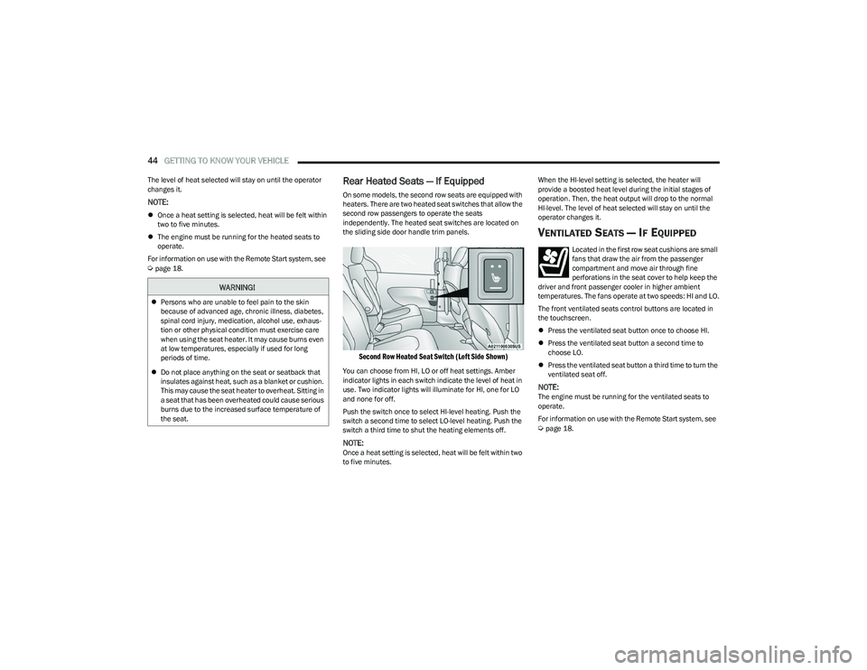
Rear Heated Seats — If Equipped
On some models, the second row seats are equipped with
heaters. There are two heated seat switches that allow the
second row passengers to operate the seats
independently. The heated seat switches are located on
the sliding side door handle trim panels.
Second Row Heated Seat Switch (Left Side Shown)
You can choose from HI, LO or off heat settings. Amber
indicator lights in each switch indicate the level of heat in
use. Two indicator lights will illuminate for HI, one for LO
and none for off.
Push the switch once to select HI-level heating. Push the
switch a second time to select LO-level heating. Push the
switch a third time to shut the heating elements off.
NOTE:Once a heat setting is selected, heat will be felt within two
to five minutes. When the HI-level setting is selected, the heater will
provide a boosted heat level during the initial stages of
operation. Then, the heat output will drop to the normal
HI-level. The level of heat selected will stay on until the
operator changes it.
VENTILATED SEATS — IF EQUIPPED
Located in the first row seat cushions are small
fans that draw the air from the passenger
compartment and move air through fine
perforations in the seat cover to help keep the
driver and front passenger cooler in higher ambient
temperatures. The fans operate at two speeds: HI and LO.
The front ventilated seats control buttons are located in
the touchscreen.
Press the ventilated seat button once to choose HI.
Press the ventilated seat button a second time to
choose LO.
Press the ventilated seat button a third time to turn the
ventilated seat off.
NOTE:The engine must be running for the ventilated seats to
operate.
For information on use with the Remote Start system, see
Úpage 18.
WARNING!
Persons who are unable to feel pain to the skin
because of advanced age, chronic illness, diabetes,
spinal cord injury, medication, alcohol use, exhaus -
tion or other physical condition must exercise care
when using the seat heater. It may cause burns even
at low temperatures, especially if used for long
periods of time.
Do not place anything on the seat or seatback that
insulates against heat, such as a blanket or cushion.
This may cause the seat heater to overheat. Sitting in
a seat that has been overheated could cause serious
burns due to the increased surface temperature of
the seat.
23_RUP_OM_EN_USC_t.book Page 44
Page 55 of 328

GETTING TO KNOW YOUR VEHICLE53
PROGRAMMING HOMELINK® TO A
M
ISCELLANEOUS DEVICE
The procedure on how to program HomeLink® to a
miscellaneous device follows the same procedure as
programming to a garage door opener
Úpage 52. Be sure
to determine if the device has a rolling code, or non-rolling
code before beginning the programming process.
NOTE:Canadian Radio Frequency (RF) laws require transmitter
signals to time-out (or quit) after several seconds of trans -
mission, which may not be long enough for HomeLink® to
pick up the signal during programming. Similar to this
Canadian law, some U.S. gate operators are designed to
time-out in the same manner. The procedure may need to
be performed multiple times to successfully pair the
device to your HomeLink® buttons.
REPROGRAMMING A SINGLE
H
OMELINK® BUTTON
To reprogram a single HomeLink® button that has been
previously trained, without erasing all the channels,
proceed as follows. Be sure to determine whether the new
device you want to program the HomeLink® button to has
a rolling code, or non-rolling code.
1. Place the ignition in the ON/RUN position, without
starting the engine.
2. Push and hold the desired HomeLink® button until the HomeLink® indicator light begins to flash after
20 seconds. Do not release the button.
3. Without releasing the button , proceed with Step 2 in
“Programming HomeLink® To A Garage Door
Opener” and follow all remaining steps.
CANADIAN/GATE OPERATOR
P
ROGRAMMING
For programming transmitters in Canada/United States
that require the transmitter signals to “time-out” after
several seconds of transmission:
Canadian Radio Frequency (RF) laws require transmitter
signals to time-out (or quit) after several seconds of
transmission, which may not be long enough for
HomeLink® to pick up the signal during programming.
Similar to this Canadian law, some U.S. gate operators are
designed to time-out in the same manner. It may be helpful to unplug the device during the cycling
process to prevent possible overheating of the garage
door or gate motor.
1. Place the ignition in the ON/RUN position.
NOTE:For vehicles equipped with Keyless Enter ‘n Go™, place
the ignition in the RUN position. Make sure while
programming HomeLink® with the engine on that your
vehicle is outside of your garage, or that the garage door
remains open at all times.
2. Place the hand-held transmitter 1 to 3 inches
(3 to 8 cm) away from the HomeLink® button you
wish to program while keeping the HomeLink®
indicator light in view.
3. Continue to push and hold the HomeLink® button while you push and release (cycle) your hand-held
transmitter every two seconds until HomeLink® has
successfully accepted the frequency signal. The
indicator light will flash slowly and then rapidly when
fully trained.
4. Watch for the HomeLink® indicator to change flash rates. When it changes, it is programmed. It may take
up to 30 seconds or longer in rare cases. The garage
door may open and close while you are programming.
5. Push and hold the programmed HomeLink® button and observe the indicator light.
WARNING!
Your motorized door or gate will open and close while
you are programming the universal transmitter. Do
not program the transmitter if people or pets are in
the path of the door or gate.
Do not run your vehicle in a closed garage or
confined area while programming the transmitter.
Exhaust gas from your vehicle contains carbon
monoxide (CO) which is odorless and colorless.
Carbon monoxide is poisonous when inhaled and
can cause you and others to be severely injured or
killed.
2
23_RUP_OM_EN_USC_t.book Page 53
Page 72 of 328

70GETTING TO KNOW YOUR VEHICLE
FLOOR MODE
Air comes from the floor outlets.
REAR CLIMATE CONTROL/BLOWER OFF
To manually set the rear blower controls to off,
press the Rear Climate Control/Blower Off
button.
AUTOMATIC TEMPERATURE CONTROL
(ATC) — I
F EQUIPPED
Automatic Operation
1. Push the AUTO button on the faceplate, or the AUTO
button on the touchscreen on the Automatic
Temperature Control (ATC) Panel.
2. Next, adjust the temperature you would like the system to maintain by adjusting the driver and
passenger temperature control buttons. Once the
desired temperature is displayed, the system will
achieve and automatically maintain that comfort
level.
3. When the system is set up for your comfort level, it is not necessary to change the settings. You will
experience the greatest efficiency by simply allowing
the system to function automatically.
NOTE:
It is not necessary to move the temperature settings for
cold or hot vehicles. The system automatically adjusts
the temperature, mode, and blower speed to provide
comfort as quickly as possible.
The temperature can be displayed in U.S. or Metric
units by selecting the U.S./Metric customer-program -
mable feature within the Uconnect system
Úpage 157.
To provide you with maximum comfort in the Automatic
mode during cold start-ups, the blower fan will remain on
low until the engine warms up. The blower will increase in
speed and transition into Auto mode.
Manual Operation Override
This system offers a full complement of manual override
features. The AUTO symbol in the front Automatic
Temperature Control (ATC) display will be turned off when
the system is being used in the manual mode.
CLIMATE VOICE COMMANDS
Adjust vehicle temperatures hands-free and keep
everyone comfortable while you keep moving ahead
(If vehicle is equipped with climate control).
Push the VR button on the steering wheel. After the beep,
say one of the following commands:
“Set driver temperature to 70 degrees ”
“Set passenger temperature to 70 degrees ”
Did you know : Voice Command for Climate may only be
used to adjust the interior temperature of your vehicle.
Voice Command will not work to adjust the heated seats
or steering wheel if equipped.
OPERATING TIPS
Refer to the chart at the end of this section for suggested
control settings for various weather conditions.
Summer Operation
The engine cooling system must be protected with a
high-quality antifreeze coolant to provide proper corrosion
protection and to protect against engine overheating. OAT
coolant (conforming to MS.90032) is recommended.
Winter Operation
To ensure the best possible heater and defroster
performance, make sure the engine cooling system is
functioning properly and the proper amount, type, and
concentration of coolant is used. Use of the Air
Recirculation mode during Winter months is not
recommended, because it may cause window fogging.
Vacation/Storage
For information on maintaining the Climate Control system
when the vehicle is being stored for an extended period of
time, see
Úpage 299.
Window Fogging
Vehicle windows tend to fog on the inside in mild, rainy,
and/or humid weather. To clear the windows, select
Defrost or Mix mode and increase the front blower speed.
Do not use the Recirculation mode without A/C for long
periods, as fogging may occur.
23_RUP_OM_EN_USC_t.book Page 70
Page 80 of 328

78GETTING TO KNOW YOUR VEHICLE
LED Indicator Status:
No Light: Charging pad is idle or searching for a device.
Blue Light: Device is detected and is charging.
Red Light/Flashing: Internal error or foreign object is
detected.
Important Notes Regarding This Vehicle’s Wireless
Charging Pad:
The wireless charging pad will not work if any of the
four doors or the liftgate are open, even if the engine is
running.
Wireless charging is not as fast as when the phone is
connected to a wired charger.
The phone’s protective case must be removed when
placed on the wireless charging pad.
iPhone® 12 (including iPod®) is equipped with soft -
ware to protect the device from overheating. When the
software is active, the rate of charge is slowed down to
protect the device.
Phones must always be placed on the wireless
charging pad within the outline shown on the pad so
that its charging parts connect with the charging coils
of the system. Movement of the phone during charging
may prevent or slow the rate of charge.
Having multiple applications open on the phone while
charging will reduce the charging efficiency, and may
even shut down an application that is actively running
(i.e. Apple CarPlay®). This may also cause the phone to
overheat.
Wireless chargers may implement certain methods to
prevent the phone from overheating during charging
such as slowing down the rate of charge. In certain instances, the device may shut down for a brief period
of time (when the device reaches a certain tempera
-
ture). If this happens, it does not mean there is a fault
with the wireless charing pad. This may just be a
protective measure to prevent damage to the phone.
WINDOWS
POWER WINDOWS
The window switches on the driver’s door trim panel
control all of the door windows.
Driver’s Power Window Controls
The driver may lock out the rear power windows by
pushing the bar control just below the power window
controls.
Window Lockout Switch
The window switches will operate only when the ignition is
in the ACC or ON/RUN position and during power
accessory delay.
NOTE:Power Window controls will also remain active for up to
10 minutes after the ignition has been placed in the OFF
position, depending upon the accessory delay setting.
Opening a front door will cancel this feature.
There is a single control on the front passenger’s door trim
panel which operates the passenger door window and a
set of controls that lock and unlock all doors. The controls
will operate only when the ignition is in the ACC or ON/RUN
position and during power accessory delay.
CAUTION!
The key fob should not be placed on the charging pad
or within 6 inches (15 cm) of it. Doing so can cause
excessive heat buildup and damage to the fob. Placing
the fob in close proximity of the charging pad blocks the
fob from being detected by the vehicle and prevents the
vehicle from starting.
23_RUP_OM_EN_USC_t.book Page 78
Page 98 of 328

96GETTING TO KNOW YOUR INSTRUMENT PANEL
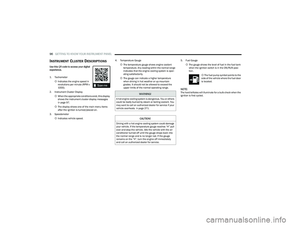
INSTRUMENT CLUSTER DESCRIPTIONS
Use this QR code to access your digital
experience.
1. Tachometer
Indicates the engine speed in
revolutions per minute (RPM x
1000).
2. Instrument Cluster Display When the appropriate conditions exist, this display
shows the instrument cluster display messages
Úpage 97.
The display shows one of the main menu items
after the ignition is turned/placed on.
3. Speedometer Indicates vehicle speed. 4. Temperature Gauge
The temperature gauge shows engine coolant
temperature. Any reading within the normal range
indicates that the engine cooling system is oper -
ating satisfactorily.
The gauge can indicate a higher temperature
when driving in hot weather or up mountain
grades. It should not be allowed to exceed the
upper limits of the normal operating range. 5. Fuel Gauge
The gauge shows the level of fuel in the fuel tank
when the ignition switch is in the ON/RUN posi -
tion.
The fuel pump symbol points to the
side of the vehicle where the fuel door
is located.
NOTE:The hard telltales will illuminate for a bulb check when the
ignition is first cycled.WARNING!
A hot engine cooling system is dangerous. You or others
could be badly burned by steam or boiling coolant. You
may want to call an authorized dealer for service if your
vehicle overheats
Úpage 271.
CAUTION!
Driving with a hot engine cooling system could damage
your vehicle. If the temperature gauge reaches “H” pull
over and stop the vehicle. Idle the vehicle with the air
conditioner turned off until the gauge drops back into
the normal range and is no longer red. If the gauge
remains on the “H”, turn the engine off immediately
and call an authorized dealer for service.
23_RUP_OM_EN_USC_t.book Page 96
Page 106 of 328

104GETTING TO KNOW YOUR INSTRUMENT PANEL
Electronic Throttle Control (ETC) Warning
Light
This warning light will illuminate to indicate a
problem with the ETC system. If a problem is
detected while the vehicle is running, the light
will either stay on or flash depending on the
nature of the problem. Cycle the ignition when the vehicle
is safely and completely stopped and the transmission is
placed in the PARK (P) position. The light should turn off.
If the light remains on with the vehicle running, your
vehicle will usually be drivable; however, see an
authorized dealer for service as soon as possible.
NOTE:This light may turn on if the accelerator and brake pedals
are pressed at the same time.
If the light continues to flash when the vehicle is running,
immediate service is required and you may experience
reduced performance, an elevated/rough idle, or engine
stall and your vehicle may require towing. The light will
come on when the ignition is placed in the ON/RUN or
ACC/ON/RUN position and remain on briefly as a bulb
check. If the light does not come on during starting, have
the system checked by an authorized dealer.
Engine Coolant Temperature Warning
Light
This warning light warns of an overheated
engine condition. If the engine coolant
temperature is too high, this indicator will
illuminate and a single chime will sound. If the
temperature reaches the upper limit, a continuous chime
will sound for four minutes or until the engine is able to
cool; whichever comes first. If the light turns on while driving, safely pull over and stop
the vehicle. If the Air Conditioning (A/C) system is on, turn
it off. Also, shift the transmission into NEUTRAL (N) and
idle the vehicle. If the temperature reading does not return
to normal, turn the engine off immediately and call for
service
Úpage 253.
Hood Open Warning Light
This warning light will illuminate when the hood
is left open and not fully closed.
NOTE:If the vehicle is moving, there will also be a single chime.
Liftgate Open Warning Light
This warning light will illuminate when the
liftgate is open.
NOTE:If the vehicle is moving, there will also be a single chime.
Oil Pressure Warning Light
This warning light will illuminate to indicate low
engine oil pressure. If the light turns on while
driving, stop the vehicle, shut off the engine as
soon as possible, and contact an authorized
dealer. A chime will sound when this light turns on.
Do not operate the vehicle until the cause is corrected.
This light does not indicate how much oil is in the engine.
The engine oil level must be checked under the hood.
Oil Temperature Warning Light
This warning light will illuminate to indicate the
engine oil temperature is high. If the light turns
on while driving, stop the vehicle and shut off
the engine as soon as possible. Wait for oil
temperature to return to normal levels.
Seat Belt Reminder Warning Light
This warning light indicates when the driver or
passenger seat belt is unbuckled. When the
ignition is first placed in the ON/RUN or ACC/
ON/RUN position and if the driver’s seat belt is
unbuckled, a chime will sound and the light will turn on.
When driving, if the driver or front passenger seat belt
remains unbuckled, the Seat Belt Reminder Light will flash
or remain on continuously and a chime will sound
Úpage 200.
Transmission Temperature Warning Light
This warning light will illuminate to warn of a
high transmission fluid temperature. This may
occur with strenuous usage such as trailer
towing. If this light turns on, stop the vehicle
and run the engine at idle or slightly faster, with the
transmission in PARK (P) or NEUTRAL (N), until the light
turns off. Once the light turns off, you may continue to
drive normally.
WARNING!
If you continue operating the vehicle when the
Transmission Temperature Warning Light is illuminated
you could cause the fluid to boil over, come in contact with
hot engine or exhaust components and cause a fire.
23_RUP_OM_EN_USC_t.book Page 104