2023 CHRYSLER PACIFICA HYBRID engine
[x] Cancel search: enginePage 90 of 328
88GETTING TO KNOW YOUR VEHICLE
(Continued)
NOTE:To access crevice or upholstery attachments, open the
front Attachment Compartment.
Crevice Tool — Able to reach into tight spaces
including the seat latches located in the floor.
Upholstery Tool — Use to agitate dirt and debris
from carpets and seats. This tool can also be used
to pick up pet hair.
Hose Extension — Use to add another 12 ft (3.6 m)
of usable length to the vacuum hose. Hose exten -
sion is provided in a bag attached to a grocery
hook behind the third row seat on the driver’s side.
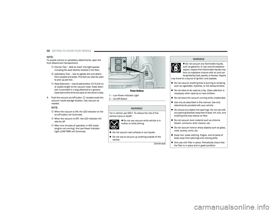
4. Push the vacuum on/off button located under the vacuum nozzle storage location. Use vacuum as
needed.
NOTE:
When the vacuum is ON, the LED indicator on the
on/off button will illuminate.
When the vacuum is OFF, the LED indicator will
also be off.
After nine minutes of operation in ACC mode
(engine not running), the Low Power Indicator
Light (LOW PWR) will illuminate.
Power Buttons
1 — Low Power Indicator Light
2 — On/Off Button
WARNING!
For in vehicle use ONLY. To reduce the risk of fire,
serious injury or death:
Do not use vacuum while vehicle is in
motion or while driving.
Do not vacuum wet surfaces or any liquids.
Do not use to vacuum up anything outside of the
vehicle.
Do not vacuum any flammable liquids,
such as gasoline, or use around explosive
vapors. Vapors from flammable liquids may
form an explosive mixture with air and can
be ignited by heat, sparks, or flames. Vapors
may travel to a source of ignition and explode.
Do not vacuum anything that is burning or smoking,
such as cigarettes, matches, or hot ashes/embers.
Do not allow to be used as a toy. Close attention is
necessary when used by or near children.
Do not leave the vacuum running while unattended.
Use only as described in this manual. Use only
attachments provided with your vehicle.
Do not put any object into openings. Do not use with
any opening blocked; keep free of dust, lint, hair, and
anything that may reduce air flow.
Do not vacuum toxic material such as chlorine
bleach, ammonia, drain cleaner, etc.
Do not vacuum hard or sharp objects such as glass,
nails, screws, coins, etc.
Keep hair, loose clothing, fingers, and all parts of
body away from openings and moving parts.
Only use with filter in place. Periodically check that
the filter is in place and in good condition.
WARNING!
23_RUP_OM_EN_USC_t.book Page 88
Page 91 of 328
GETTING TO KNOW YOUR VEHICLE89
5. When finished, push power button to turn vacuum off
and store vacuum hose and any attachments.
6. Before exiting the vehicle: If the ignition is in the ACC position, push the
START/STOP ignition button to place ignition in the
OFF position, remove key fob from the vehicle, and
lock the vehicle.
If the engine is running, raise all of the windows,
push the START/STOP ignition button to place igni -
tion in the OFF position, remove key fob from the
vehicle, close all of the doors and the liftgate and
lock the vehicle.
Vacuum Troubleshooting
DO NOT use with any opening blocked. If an object
becomes lodged in the hose, attempt to fully extend
the hose in a straight line while the vacuum motor is
running. If this does not dislodge the object, turn the
vacuum OFF and remove the hose from the vehicle
using the subsequent removal instructions. If the filter
is clogged, follow the emptying debris bin procedure
and lightly tap the filter on the collection bin to remove any collected debris from the filter. Both the bin and
the filter can be rinsed with water if needed. To avoid
mold and stale odors, allow both to dry completely
before reinstalling in your vehicle. If the filter has tears,
holes or other damage and needs to be replaced,
please contact an authorized dealer.
If there are any other issues with your vacuum, contact
an authorized dealer. Your vacuum has no user
serviceable parts.
Debris Bin
The debris bin is located behind the access panel behind
the third row seat on the driver’s side.
To Empty
1. Push power button to turn vacuum OFF.
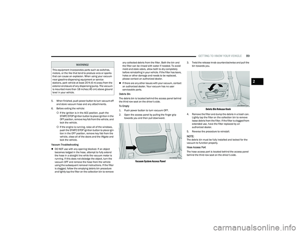
2. Open the access panel by pulling the finger grip towards you and then pull downward.
Vacuum System Access Panel
3. Twist the release knob counterclockwise and pull the bin towards you.
Debris Bin Release Knob
4. Remove the filter and dump the debris in a trash can. Lightly tap the filter on the collection bin to remove
loose debris from the filter. If the filter is clogged from
extended use, have the filter replaced by an
authorized dealer.
5. Reverse the procedure to reinstall.
NOTE:The debris bin must be fully installed and locked for the
vacuum to function properly.
Hose Access Port
The hose access port is located behind the access panel
behind the third row seat on the driver’s side.
WARNING!
This equipment incorporates parts such as switches,
motors, or the like that tend to produce arcs or sparks
that can cause an explosion. When using your vacuum
near gasoline-dispensing equipment or service
stations, park vehicle at least 20 ft (6 m) away from the
exterior enclosure of any dispensing pump. The vacuum
is mounted more than 18 inches (45 cm) above ground
level in your vehicle.
2
23_RUP_OM_EN_USC_t.book Page 89
Page 98 of 328
96GETTING TO KNOW YOUR INSTRUMENT PANEL
INSTRUMENT CLUSTER DESCRIPTIONS
Use this QR code to access your digital
experience.
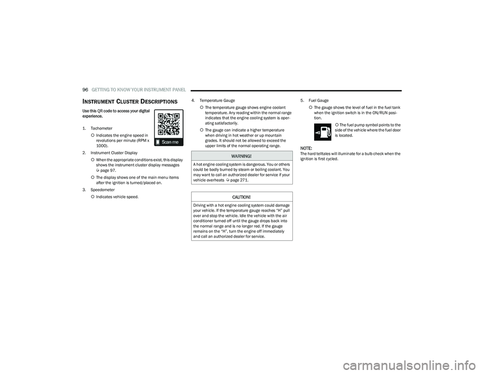
1. Tachometer
Indicates the engine speed in
revolutions per minute (RPM x
1000).
2. Instrument Cluster Display When the appropriate conditions exist, this display
shows the instrument cluster display messages
Úpage 97.
The display shows one of the main menu items
after the ignition is turned/placed on.
3. Speedometer Indicates vehicle speed. 4. Temperature Gauge
The temperature gauge shows engine coolant
temperature. Any reading within the normal range
indicates that the engine cooling system is oper -
ating satisfactorily.
The gauge can indicate a higher temperature
when driving in hot weather or up mountain
grades. It should not be allowed to exceed the
upper limits of the normal operating range. 5. Fuel Gauge
The gauge shows the level of fuel in the fuel tank
when the ignition switch is in the ON/RUN posi -
tion.
The fuel pump symbol points to the
side of the vehicle where the fuel door
is located.
NOTE:The hard telltales will illuminate for a bulb check when the
ignition is first cycled.WARNING!
A hot engine cooling system is dangerous. You or others
could be badly burned by steam or boiling coolant. You
may want to call an authorized dealer for service if your
vehicle overheats
Úpage 271.
CAUTION!
Driving with a hot engine cooling system could damage
your vehicle. If the temperature gauge reaches “H” pull
over and stop the vehicle. Idle the vehicle with the air
conditioner turned off until the gauge drops back into
the normal range and is no longer red. If the gauge
remains on the “H”, turn the engine off immediately
and call an authorized dealer for service.
23_RUP_OM_EN_USC_t.book Page 96
Page 100 of 328

98GETTING TO KNOW YOUR INSTRUMENT PANEL
Back / Left Arrow Button
Push and release the left arrow button to access
the information screens or submenu screens of a main
menu item.
Up Arrow Button
Push and release the up arrow button to scroll
upward through the Main Menu items.
Right Arrow Button
Push and release the right arrow button to access
the information screens or submenu screens of a main
menu item.
Down Arrow Button
Push and release the down arrow button to scroll
downward through the Main Menu items.
OK Button
Push the OK button to access/select the information
screens or submenu screens of a Main Menu item.
Push and hold the OK button for two seconds to reset
displayed/selected features that can be reset.
ENGINE OIL LIFE
Use this QR code to access your digital
experience.
Your vehicle is equipped with an
engine oil change indicator system.
The “Oil Change Required”
message will display for approxi -
mately five seconds after a single
chime has sounded, to indicate it is
time to change the engine oil. The engine oil change indicator system is duty cycle based, which means the
engine oil change interval may fluctuate, dependent
upon your personal driving style.
Unless reset, this message will continue to display
each time the ignition is cycled to the ON/RUN position.
To reset the oil change indicator after performing the
scheduled maintenance, refer to the following proce -
dure.
NOTE:This procedure should only be performed after scheduled
maintenance is completed. Resetting oil life other than
when associated with a scheduled maintenance may
result in damage due to not properly maintaining the
engine oil.
Oil Life Reset
1. Without pressing the brake pedal, push the ENGINE START/STOP button and place the ignition in the
ON/RUN position (do not start the vehicle.)
2. Push the OK button to enter the instrument cluster
display menu screen.
3. Push and release the down arrow button to
access the ”Vehicle Info” menu screen.
4. Push the left arrow button or right arrow button
to access the “Oil Life” submenu.
5. Hold the OK button to reset the “Oil Life” to 100%.
6. Push the up arrow button to exit the instrument
cluster display menu screen. Secondary Method For Oil Life Reset Procedure
1. Without pushing the brake pedal, place the ignition
in the ON/RUN position (do not start the engine).
2. Fully press the accelerator pedal, slowly, three times within 10 seconds.
3. Without pushing the brake pedal, place the ignition in the OFF position.
NOTE:If the indicator message illuminates when you start the
vehicle, the oil change indicator system did not reset. If
necessary, repeat this procedure.
KEYSENSE CLUSTER MESSAGES —
I
F EQUIPPED
When the KeySense key is in use there will be:
Continuous, dedicated telltale
Unique Display Splash Screen
With KeySense in use there will be multiple associated
messages shown in the following table:
Setting Instrument Cluster Display
Message
None – With vehicle ignition ON “KeySense in use. Max
vehicle speed set to xx MPH/or km/h”
23_RUP_OM_EN_USC_t.book Page 98
Page 102 of 328
100GETTING TO KNOW YOUR INSTRUMENT PANEL
Oil Life
Displays the remaining engine oil life as a percentage.
To reset the Oil Life, you must hold the OK button. The
“Hold OK to Reset” instruction will be displayed at all
times, but the following conditions will need to be met in
order to reset Oil Life:
The ignition must be in the ON/RUN position.
If the conditions are met, holding the OK button will reset
the gauge and the numeric display will return to 100%.
If the conditions are not met, a pop-up message will
display for five seconds, describing the required
conditions, and then the Oil Life screen will reappear.
Battery Voltage
Displays the actual battery voltage.
Engine Hours — If Equipped
Displays the number of hours of engine operation.
Driver Assist — If Equipped
Push and release the up or down arrow button until
the Driver Assist display icon is highlighted in the
instrument cluster display.
Adaptive Cruise Control
LaneSense
Fuel Economy
Push and release the up or down arrow button until
the Fuel Economy Menu item is highlighted in the
instrument cluster display. The Fuel Economy Menu will
display the following:
Two submenu pages that can be toggled between
using the left and right arrow buttons; one with
Current Value displayed and one without the Current
Value displayed:
Average Fuel Economy (MPG, L/100 km, or km/L)
Range To Empty (miles or km)
Current Fuel Economy (MPG, L/100 km, or km/L)
The Max and Min values will correspond to the
particular engine requirements
Hold OK to reset average fuel economy information.
Trip Info
Push and release the up or down arrow button until
the Trip Menu item is highlighted in the instrument cluster
display. Push the left or right arrow button to scroll
through the Trip A and Trip B submenus. The Trip
information will display the following:
Distance
Average Fuel Economy
Elapsed Time
Hold the OK button to reset feature information.
Stop / Start – If Equipped
Push and release the up or down arrow button until
the Stop/Start menu title is displayed in the instrument
cluster display.
Audio
Push and release the up or down arrow button until
the Audio Menu displays in the instrument cluster display.
Messages
Push and release the up or down arrow button until
Messages is highlighted in the instrument cluster display.
This feature shows the number of stored warning
messages. Pushing the right arrow button will allow you
to see what the stored messages are.
NOTE:The pop-up messages indicate the status of the system
and/or the conditions that need to be met. Messages
remain in the stored stack until condition is cleared.
Screen Setup
Push and release the up or down arrow button until
the Screen Setup Menu displays in the instrument cluster
display. Push and release the OK button to enter the
submenus. The Screen Setup feature allows you to
change what information is displayed in the instrument
cluster as well as the location that information is
displayed.
23_RUP_OM_EN_USC_t.book Page 100
Page 104 of 328

102GETTING TO KNOW YOUR INSTRUMENT PANEL
NOTE:
The charging system is independent from load reduc -
tion. The charging system performs a diagnostic on the
charging system continuously.
If the Battery Charge Warning Light is on it may indicate
a problem with the charging system
Úpage 103.
The electrical loads that may be switched off (if equipped),
and vehicle functions which can be effected by load
reduction:
Heated Seat/Vented Seats/Heated Wheel
Heated/Cooled Cup Holders — If Equipped
Rear Defroster And Heated Mirrors
HVAC System
115 Volts AC Power Inverter System
Audio and Telematics System
Loss of the battery charge may indicate one or more of the
following conditions:
The charging system cannot deliver enough electrical
power to the vehicle system because the electrical
loads are larger than the capability of charging system.
The charging system is still functioning properly.
Turning on all possible vehicle electrical loads (e.g.
HVAC to max settings, exterior and interior lights, over -
loaded power outlets +12 Volts, 150W, USB ports)
during certain driving conditions (city driving, towing,
frequent stopping).
Installing options like additional lights, upfitter elec -
trical accessories, audio systems, alarms and similar
devices.
Unusual driving cycles (short trips separated by long
parking periods).
The vehicle was parked for an extended period of time
(weeks, months).
The battery was recently replaced and was not charged
completely.
The battery was discharged by an electrical load left on
when the vehicle was parked.
The battery was used for an extended period with the
engine not running to supply radio, lights, chargers,
+12 Volt portable appliances like vacuum cleaners,
game consoles and similar devices.
What to do when an electrical load reduction action
message is present (“Battery Saver On” or “Battery Saver
Mode”)
During a trip:
Reduce power to unnecessary loads if possible:
Turn off redundant lights (interior or exterior)
Check what may be plugged in to power outlets
+12 Volts, 150W, USB ports
Check HVAC settings (blower, temperature)
Check the audio settings (volume)
After a trip:
Check if any aftermarket equipment was installed
(additional lights, upfitter electrical accessories, audio
systems, alarms) and review specifications if any (load
and Ignition Off Draw currents).
Evaluate the latest driving cycles (distance, driving
time and parking time).
The vehicle should have service performed if the
message is still present during consecutive trips and
the evaluation of the vehicle and driving pattern did not
help to identify the cause.
WARNING LIGHTS AND MESSAGES
The warning/indicator lights will illuminate in the
instrument panel together with a dedicated message and/
or acoustic signal when applicable. These indications are
indicative and precautionary and as such must not be
considered as exhaustive and/or alternative to the
information contained in the Owner’s Manual, which you
are advised to read carefully in all cases. Always refer to
the information in this chapter in the event of a failure
indication. All active telltales will display first if applicable.
The system check menu may appear different based upon
equipment options and current vehicle status. Some
telltales are optional and may not appear.
RED WARNING LIGHTS
Air Bag Warning Light
This warning light will illuminate to indicate a
fault with the air bag, and will turn on for four to
eight seconds as a bulb check when the ignition
is placed in the ON/RUN or ACC/ON/RUN
position. This light will illuminate with a single chime when a
fault with the air bag has been detected, it will stay on until
the fault is cleared. If the light is either not on during startup,
stays on, or turns on while driving, have the system
inspected at an authorized dealer as soon as possible.
23_RUP_OM_EN_USC_t.book Page 102
Page 105 of 328
GETTING TO KNOW YOUR INSTRUMENT PANEL103
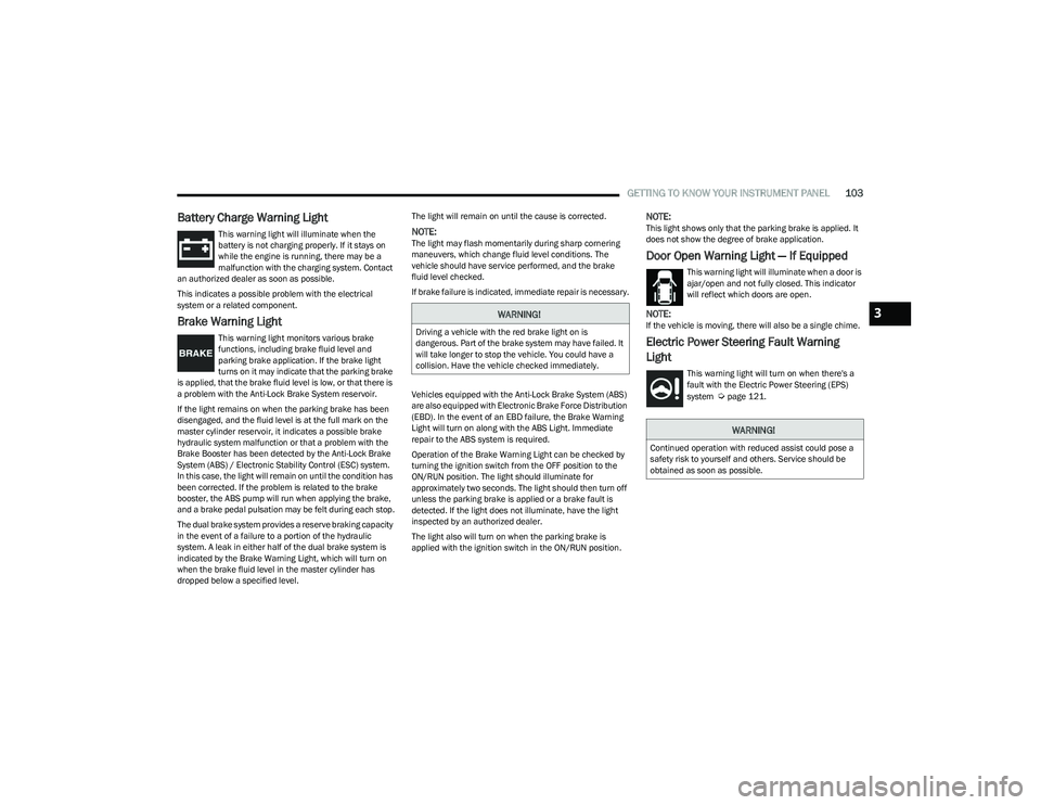
Battery Charge Warning Light
This warning light will illuminate when the
battery is not charging properly. If it stays on
while the engine is running, there may be a
malfunction with the charging system. Contact
an authorized dealer as soon as possible.
This indicates a possible problem with the electrical
system or a related component.
Brake Warning Light
This warning light monitors various brake
functions, including brake fluid level and
parking brake application. If the brake light
turns on it may indicate that the parking brake
is applied, that the brake fluid level is low, or that there is
a problem with the Anti-Lock Brake System reservoir.
If the light remains on when the parking brake has been
disengaged, and the fluid level is at the full mark on the
master cylinder reservoir, it indicates a possible brake
hydraulic system malfunction or that a problem with the
Brake Booster has been detected by the Anti-Lock Brake
System (ABS) / Electronic Stability Control (ESC) system.
In this case, the light will remain on until the condition has
been corrected. If the problem is related to the brake
booster, the ABS pump will run when applying the brake,
and a brake pedal pulsation may be felt during each stop.
The dual brake system provides a reserve braking capacity
in the event of a failure to a portion of the hydraulic
system. A leak in either half of the dual brake system is
indicated by the Brake Warning Light, which will turn on
when the brake fluid level in the master cylinder has
dropped below a specified level. The light will remain on until the cause is corrected.
NOTE:The light may flash momentarily during sharp cornering
maneuvers, which change fluid level conditions. The
vehicle should have service performed, and the brake
fluid level checked.
If brake failure is indicated, immediate repair is necessary.
Vehicles equipped with the Anti-Lock Brake System (ABS)
are also equipped with Electronic Brake Force Distribution
(EBD). In the event of an EBD failure, the Brake Warning
Light will turn on along with the ABS Light. Immediate
repair to the ABS system is required.
Operation of the Brake Warning Light can be checked by
turning the ignition switch from the OFF position to the
ON/RUN position. The light should illuminate for
approximately two seconds. The light should then turn off
unless the parking brake is applied or a brake fault is
detected. If the light does not illuminate, have the light
inspected by an authorized dealer.
The light also will turn on when the parking brake is
applied with the ignition switch in the ON/RUN position.
NOTE:This light shows only that the parking brake is applied. It
does not show the degree of brake application.
Door Open Warning Light — If Equipped
This warning light will illuminate when a door is
ajar/open and not fully closed. This indicator
will reflect which doors are open.
NOTE:If the vehicle is moving, there will also be a single chime.
Electric Power Steering Fault Warning
Light
This warning light will turn on when there's a
fault with the Electric Power Steering (EPS)
system
Úpage 121.
WARNING!
Driving a vehicle with the red brake light on is
dangerous. Part of the brake system may have failed. It
will take longer to stop the vehicle. You could have a
collision. Have the vehicle checked immediately.
WARNING!
Continued operation with reduced assist could pose a
safety risk to yourself and others. Service should be
obtained as soon as possible.
3
23_RUP_OM_EN_USC_t.book Page 103
Page 106 of 328
104GETTING TO KNOW YOUR INSTRUMENT PANEL
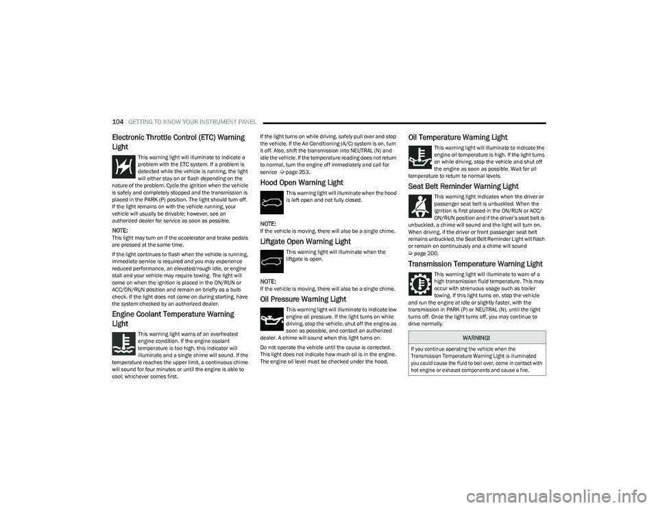
Electronic Throttle Control (ETC) Warning
Light
This warning light will illuminate to indicate a
problem with the ETC system. If a problem is
detected while the vehicle is running, the light
will either stay on or flash depending on the
nature of the problem. Cycle the ignition when the vehicle
is safely and completely stopped and the transmission is
placed in the PARK (P) position. The light should turn off.
If the light remains on with the vehicle running, your
vehicle will usually be drivable; however, see an
authorized dealer for service as soon as possible.
NOTE:This light may turn on if the accelerator and brake pedals
are pressed at the same time.
If the light continues to flash when the vehicle is running,
immediate service is required and you may experience
reduced performance, an elevated/rough idle, or engine
stall and your vehicle may require towing. The light will
come on when the ignition is placed in the ON/RUN or
ACC/ON/RUN position and remain on briefly as a bulb
check. If the light does not come on during starting, have
the system checked by an authorized dealer.
Engine Coolant Temperature Warning
Light
This warning light warns of an overheated
engine condition. If the engine coolant
temperature is too high, this indicator will
illuminate and a single chime will sound. If the
temperature reaches the upper limit, a continuous chime
will sound for four minutes or until the engine is able to
cool; whichever comes first. If the light turns on while driving, safely pull over and stop
the vehicle. If the Air Conditioning (A/C) system is on, turn
it off. Also, shift the transmission into NEUTRAL (N) and
idle the vehicle. If the temperature reading does not return
to normal, turn the engine off immediately and call for
service
Úpage 253.
Hood Open Warning Light
This warning light will illuminate when the hood
is left open and not fully closed.
NOTE:If the vehicle is moving, there will also be a single chime.
Liftgate Open Warning Light
This warning light will illuminate when the
liftgate is open.
NOTE:If the vehicle is moving, there will also be a single chime.
Oil Pressure Warning Light
This warning light will illuminate to indicate low
engine oil pressure. If the light turns on while
driving, stop the vehicle, shut off the engine as
soon as possible, and contact an authorized
dealer. A chime will sound when this light turns on.
Do not operate the vehicle until the cause is corrected.
This light does not indicate how much oil is in the engine.
The engine oil level must be checked under the hood.
Oil Temperature Warning Light
This warning light will illuminate to indicate the
engine oil temperature is high. If the light turns
on while driving, stop the vehicle and shut off
the engine as soon as possible. Wait for oil
temperature to return to normal levels.
Seat Belt Reminder Warning Light
This warning light indicates when the driver or
passenger seat belt is unbuckled. When the
ignition is first placed in the ON/RUN or ACC/
ON/RUN position and if the driver’s seat belt is
unbuckled, a chime will sound and the light will turn on.
When driving, if the driver or front passenger seat belt
remains unbuckled, the Seat Belt Reminder Light will flash
or remain on continuously and a chime will sound
Úpage 200.
Transmission Temperature Warning Light
This warning light will illuminate to warn of a
high transmission fluid temperature. This may
occur with strenuous usage such as trailer
towing. If this light turns on, stop the vehicle
and run the engine at idle or slightly faster, with the
transmission in PARK (P) or NEUTRAL (N), until the light
turns off. Once the light turns off, you may continue to
drive normally.
WARNING!
If you continue operating the vehicle when the
Transmission Temperature Warning Light is illuminated
you could cause the fluid to boil over, come in contact with
hot engine or exhaust components and cause a fire.
23_RUP_OM_EN_USC_t.book Page 104