2023 CHRYSLER PACIFICA HYBRID instrument panel
[x] Cancel search: instrument panelPage 3 of 328

TABLE OF CONTENTS
1
2
3
4
5
6
7
8
9
10
11
1 INTRODUCTION .............................................................................................................................. 7
2 GETTING TO KNOW YOUR VEHICLE ..................................................................................12
3 GETTING TO KNOW YOUR INSTRUMENT PANEL ....................................................... 94
4 STARTING AND OPERATING ................................................................................................. 111 5 MULTIMEDIA ............................................................................................................................... 157
6 SAFETY ......................................................................................................................................... 187 7 IN CASE OF EMERGENCY .................................................................................................... 236
8 SERVICING AND MAINTENANCE ...................................................................................... 259
9 TECHNICAL SPECIFICATIONS ............................................................................................303
10 CUSTOMER ASSISTANCE .....................................................................................................308 11 INDEX .............................................................................................................................................. 313
23_RUP_OM_EN_USC_t.book Page 1
Page 5 of 328

3
EXTERIOR LIGHTS ..............................................................54Multifunction Lever ..................................................... 54
Headlight Switch ......................................................... 55
Daytime Running Lights (DRLs) — If Equipped.......... 55
High/Low Beam Switch .............................................. 56
Automatic High Beam — If Equipped ........................ 56
Flash-To-Pass .............................................................. 56
Automatic Headlights — If Equipped ......................... 56
Headlights On With Wipers —If Equipped .................. 56
Headlight Time Delay — If Equipped .......................... 56
Lights-On Reminder .................................................... 57
Front Fog Lights — If Equipped .................................. 57
Turn Signals................................................................. 57
Lane Change Assist — If Equipped............................. 57
Battery Saver .............................................................. 57
INTERIOR LIGHTS ...............................................................58 Interior Courtesy Lights .............................................. 58
WINDSHIELD WIPER AND WASHERS .............................59 Windshield Wiper Operation....................................... 59
Rain Sensing Wipers — If Equipped ........................... 60
Rear Wiper And Washer ............................................. 60
CLIMATE CONTROLS .........................................................60 Automatic Climate Control Descriptions
And Functions.............................................................. 61
Manual Climate Control Descriptions
And Functions.............................................................. 66
Automatic Temperature Control (ATC) —
If Equipped ................................................................. 70
Climate Voice Commands .......................................... 70
Operating Tips ............................................................ 70 INTERIOR STORAGE AND EQUIPMENT ............................ 71
Storage ......................................................................... 71
Lighted Cupholders — If Equipped..............................74
Sun Screens — If Equipped ......................................... 74
USB/AUX Control ........................................................ 74
Power Outlets .............................................................. 75
Power Inverter — If Equipped ..................................... 77
Wireless Charging Pad — If Equipped......................... 77
WINDOWS............................................................................ 78 Power Windows............................................................ 78
Automatic Window Features ....................................... 79
Reset Auto-Up .............................................................. 79
Wind Buffeting ............................................................. 79
PANORAMIC SUNROOF — IF EQUIPPED .......................... 80 Opening And Closing The Sunroof ..............................80
Opening And Closing The Power Sunshade —
If Equipped ................................................................... 81
Pinch Protect Feature.................................................. 81
Venting Sunroof ........................................................... 81
Ignition Off Operation .................................................. 81
Sunroof Maintenance.................................................. 81
HOOD.................................................................................... 82 Opening ........................................................................ 82
Closing .......................................................................... 82
LIFTGATE .............................................................................. 83 To Unlock/Open The Liftgate ......................................83
To Lock/Close The Liftgate ......................................... 83
Power Liftgate — If Equipped ......................................83
Hands-Free Liftgate — If Equipped ............................. 84
Cargo Area Features ................................................... 86 STOW ‘N PLACE ROOF RACK — IF EQUIPPED ............... 90
Deploying The Crossbars ............................................ 91
Stowing The Crossbars ............................................... 92
GETTING TO KNOW YOUR
INSTRUMENT PANEL
INSTRUMENT CLUSTER ..................................................... 94 Instrument Cluster Descriptions ................................ 96
INSTRUMENT CLUSTER DISPLAY .................................... 97 Instrument Cluster Display Location And Controls ... 97
Engine Oil Life ............................................................. 98
KeySense Cluster Messages — If Equipped .............. 98
Instrument Cluster Display Menu Items ................... 99
Battery Saver On/Battery Saver Mode Message —
Electrical Load Reduction Actions — If Equipped ... 101
WARNING LIGHTS AND MESSAGES ..............................102 Red Warning Lights ................................................... 102
Yellow Warning Lights ............................................... 105Yellow Indicator Lights .............................................. 107Green Indicator Lights............................................... 107White Indicator Lights ............................................... 108Blue Indicator Lights ................................................. 109
ONBOARD DIAGNOSTIC SYSTEM — OBD II ................... 109 Onboard Diagnostic System
(OBD II) Cybersecurity ............................................... 109
EMISSIONS INSPECTION AND MAINTENANCE
PROGRAMS ....................................................................... 110
23_RUP_OM_EN_USC_t.book Page 3
Page 26 of 328
24GETTING TO KNOW YOUR VEHICLE
POWER SLIDING SIDE DOOR —
I
F EQUIPPED
The power sliding door may be power opened or closed in
several ways:
Key fob
Inside or outside handles
Buttons located:
In the overhead console
Just inside the sliding door
On the outside handle
Push the button on the key fob twice within five
seconds to open, close, or reverse a power
sliding door.
The key fob and the overhead console button will operate
the door when the door is locked. All other ways require
the sliding door to be unlocked. If the vehicle is equipped
with Passive Entry, pushing the button on the outside
handle or Hands-Free feature (if equipped) will unlock and
open the sliding door, with a valid Passive Entry key fob
within 5 ft (1.5 m) of the door handle.
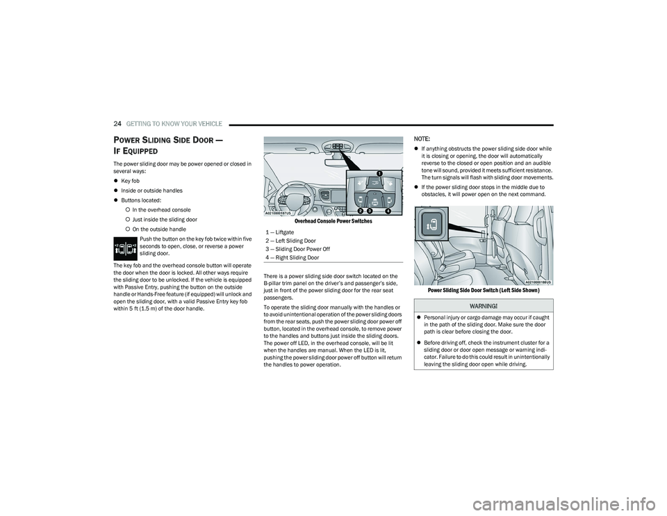
Overhead Console Power Switches
There is a power sliding side door switch located on the
B-pillar trim panel on the driver’s and passenger’s side,
just in front of the power sliding door for the rear seat
passengers.
To operate the sliding door manually with the handles or
to avoid unintentional operation of the power sliding doors
from the rear seats, push the power sliding door power off
button, located in the overhead console, to remove power
to the handles and buttons just inside the sliding doors.
The power off LED, in the overhead console, will be lit
when the handles are manual. When the LED is lit,
pushing the power sliding door power off button will return
the handles to power operation.
NOTE:
If anything obstructs the power sliding side door while
it is closing or opening, the door will automatically
reverse to the closed or open position and an audible
tone will sound, provided it meets sufficient resistance.
The turn signals will flash with sliding door movements.
If the power sliding door stops in the middle due to
obstacles, it will power open on the next command.
Power Sliding Side Door Switch (Left Side Shown)
1 — Liftgate
2 — Left Sliding Door
3 — Sliding Door Power Off
4 — Right Sliding Door
WARNING!
Personal injury or cargo damage may occur if caught
in the path of the sliding door. Make sure the door
path is clear before closing the door.
Before driving off, check the instrument cluster for a
sliding door or door open message or warning indi -
cator. Failure to do this could result in unintentionally
leaving the sliding door open while driving.
23_RUP_OM_EN_USC_t.book Page 24
Page 38 of 328
36GETTING TO KNOW YOUR VEHICLE
2. Pulling strap “2” releases the seatback to return to its
full upright position.
Strap “2”
3. Raise the head restraint to its upright position.
Stow 'n Go Seating
On vehicles equipped with Stow 'n Go seating, the second
and third row seats can be folded into the floor for
convenient storage.
AUTO ADVANCE ‘N RETURN — IF EQUIPPED
On vehicles equipped with the Auto Advance ‘n Return
feature, the front seat will move forward automatically to
a location that will allow the second row Stow ‘n Go seat
movement, without interference by the front seat. After
the second row seat is stowed, the front seat will move
back to the previous location once the Auto Advance ‘n
Return button is pushed again.
The Auto Advance ‘n Return feature is available to both the
front driver and passenger power seats (if equipped).
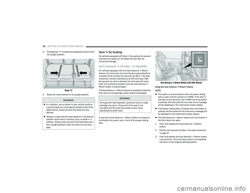
A one-touch Auto Advance ‘n Return button is located on
the B-pillar trim panel, just in front of the power sliding
door.
Auto Advance ‘n Return Button (Left Side Shown)
Using the Auto Advance ‘n Return Feature
NOTE:
The button is only functional when the power sliding
door is open and the vehicle is in PARK. If the door is
not open or the vehicle is not in PARK when the button
is pushed, the front seat will not move and a message
will be displayed in the instrument cluster display.
If the power sliding door is closing when the button is
pushed, the front seat will not move and a message will
be displayed in the instrument cluster display.
The Auto Advance ‘n Return feature will not function if
the front doors are open.
1. Push and release the Auto Advance ‘n Return button.
2. Perform the second row Stow ‘n Go seat movement
Úpage 37.
3. Push and release the Auto Advance ‘n Return button a second time. The front seat cushion and seatback
will return to the original starting location.
WARNING!
In a collision, you or others in your vehicle could be
injured if seats are not properly latched to their floor
attachments. Always be sure the seats are fully
latched.
Sitting in a seat with the head restraint in its lowered
position could result in serious injury or death in a
collision. Always make sure the head restraints are in
their upright positions when the seat is to be occu -
pied.
WARNING!
During power seat operation, personal injury or cargo
damage may occur. Ensure the front seat is not
occupied and the seat travel path is clear when
operating the power seat.
23_RUP_OM_EN_USC_t.book Page 36
Page 39 of 328
GETTING TO KNOW YOUR VEHICLE37
NOTE:
To abort seat operation while seat is in motion, push
the Auto Advance ‘n Return button, or push the front
power seat button to stop the seat movement. Pushing
the Auto Advance ‘n Return button again will return the
front seat to the original starting location.
The Auto Advance ‘n Return system includes obstacle
detection. When the system detects an obstacle, the
seat will stop, reverse direction, and return to the
previous location. A message will be displayed in the
instrument cluster indicating that an obstacle has been
detected.
If the front seat is already in a location that will allow
space for Stow ‘n Go of the second row seat, the front
seat will not move and a message will be displayed in
the instrument cluster.
If calibration of the front seat is lost, the seat will auto -
matically recalibrate when the Auto Advance ‘n Return
button is pushed. This may result in the seat cushion
moving forward and downward, before moving to the
location that will allow space for the second row Stow
‘n Go seat movement.
SECOND ROW STOW 'N GO
For Manual Seats: To stow the seat in the floor, move the
front seat all the way forward using the manual seat
adjustment bar. Move the seatback all the way forward
using the recliner handle located on the outboard side of
the cushion. Move the seat height to at least mid position
using the height adjuster handle in the outboard side of
the cushion. For Power Seats:
Push the Auto Advance ‘n Return button
located on the B-pillar trim (if equipped)
Úpage 36.
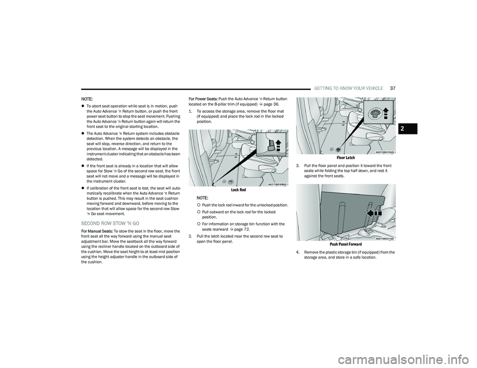
1. To access the storage area, remove the floor mat (if equipped) and place the lock rod in the locked
position.
Lock Rod
NOTE:
Push the lock rod inward for the unlocked position.
Pull outward on the lock rod for the locked
position.
For information on storage bin function with the
seats rearward
Úpage 72.
2. Pull the latch located near the second row seat to open the floor panel.
Floor Latch
3. Pull the floor panel and position it toward the front seats while folding the top half down, and rest it
against the front seats.
Push Panel Forward
4. Remove the plastic storage bin (if equipped) from the storage area, and store in a safe location.
2
23_RUP_OM_EN_USC_t.book Page 37
Page 57 of 328
GETTING TO KNOW YOUR VEHICLE55
HEADLIGHT SWITCH
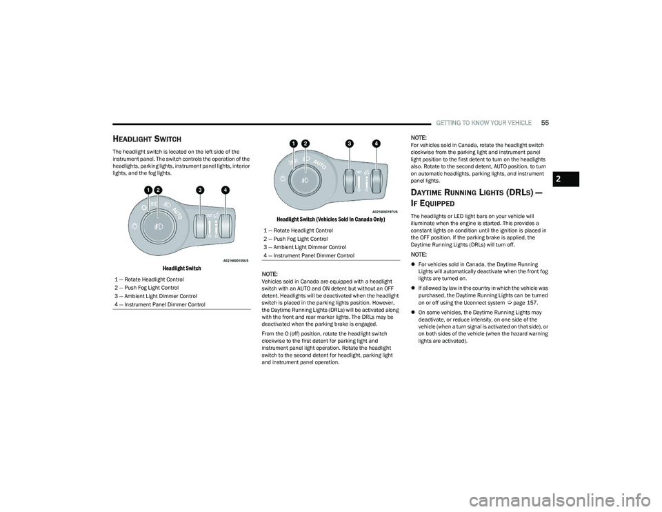
The headlight switch is located on the left side of the
instrument panel. The switch controls the operation of the
headlights, parking lights, instrument panel lights, interior
lights, and the fog lights.
Headlight Switch Headlight Switch (Vehicles Sold In Canada Only)
NOTE:
Vehicles sold in Canada are equipped with a headlight
switch with an AUTO and ON detent but without an OFF
detent. Headlights will be deactivated when the headlight
switch is placed in the parking lights position. However,
the Daytime Running Lights (DRLs) will be activated along
with the front and rear marker lights. The DRLs may be
deactivated when the parking brake is engaged.
From the O (off) position, rotate the headlight switch
clockwise to the first detent for parking light and
instrument panel light operation. Rotate the headlight
switch to the second detent for headlight, parking light
and instrument panel operation.
NOTE:For vehicles sold in Canada, rotate the headlight switch
clockwise from the parking light and instrument panel
light position to the first detent to turn on the headlights
also. Rotate to the second detent, AUTO position, to turn
on automatic headlights, parking lights, and instrument
panel lights.
DAYTIME RUNNING LIGHTS (DRLS) —
I
F EQUIPPED
The headlights or LED light bars on your vehicle will
illuminate when the engine is started. This provides a
constant lights on condition until the ignition is placed in
the OFF position. If the parking brake is applied, the
Daytime Running Lights (DRLs) will turn off.
NOTE:
For vehicles sold in Canada, the Daytime Running
Lights will automatically deactivate when the front fog
lights are turned on.
If allowed by law in the country in which the vehicle was
purchased, the Daytime Running Lights can be turned
on or off using the Uconnect system
Úpage 157.
On some vehicles, the Daytime Running Lights may
deactivate, or reduce intensity, on one side of the
vehicle (when a turn signal is activated on that side), or
on both sides of the vehicle (when the hazard warning
lights are activated).
1 — Rotate Headlight Control
2 — Push Fog Light Control
3 — Ambient Light Dimmer Control
4 — Instrument Panel Dimmer Control
1 — Rotate Headlight Control
2 — Push Fog Light Control
3 — Ambient Light Dimmer Control
4 — Instrument Panel Dimmer Control
2
23_RUP_OM_EN_USC_t.book Page 55
Page 58 of 328
56GETTING TO KNOW YOUR VEHICLE
HIGH/LOW BEAM SWITCH
Push the multifunction lever toward the instrument panel
to switch the headlights to high beams. Pulling the
multifunction lever back will turn the low beams on.
AUTOMATIC HIGH BEAM — IF EQUIPPED
The Automatic High Beam system provides increased
forward lighting at night by automatically controlling the
high beams through the use of a camera mounted on the
windshield. This camera detects vehicle specific light and
automatically switches from high beams to low beams
until the approaching vehicle is out of view.
NOTE:Broken, muddy, or obstructed headlights and taillights of
vehicles in the field of view will cause headlights to remain
on longer (closer to the vehicle). Also, dirt, film and other
obstructions on the windshield or camera lens will cause
the system to function improperly.
To Activate
1. Select “Auto Dim High Beams” through the
Uconnect system to enable the feature
Ú
page 157.
2. Rotate the headlight switch clockwise to the AUTO position.
3. Push the multifunction lever away from you to switch the headlights to the high beam position. Refer to
“Multifunction Lever” in this section for further
information.
NOTE:This system will not activate until the vehicle is at, or
above 16 mph (25 km/h).
To Deactivate
Perform either of the following steps to deactivate the
Automatic High Beam system.
1. Deselect “Auto Dim High Beams” through the
Uconnect system
Ú
page 157.
2. Pull the multifunction lever toward you to switch the headlights from the high beam to the low beam
position.
3. Rotate the headlight switch counterclockwise from the AUTO to the on position.
NOTE:Once active, the Automatic High Beam system will stop
functioning below 12 mph (20 km/h).
FLASH-TO-PASS
You can signal another vehicle with your headlights by
lightly pulling the multifunction lever toward you. This will
cause the high beam headlights to turn on, and remain on,
until the lever is released.
AUTOMATIC HEADLIGHTS — IF EQUIPPED
This system automatically turns your headlights on or off
based on ambient light levels. To turn the system on, turn
the headlight switch to the extreme clockwise position
aligning the indicator with the AUTO on the headlight
switch. When the system is on, the Headlight Time Delay
feature is also on. This means your headlights will stay on
for up to 90 seconds after the ignition is placed in the OFF
position. To turn the automatic system off, move the
headlight switch out of the AUTO position.
NOTE:The engine must be running before the headlights will
come on in the Automatic mode.
HEADLIGHTS ON WITH WIPERS —
I
F EQUIPPED
When your headlights are in the AUTO mode and the
engine is running, the headlights will automatically turn on
when the wiper system is also turned on. Headlights on
when windshield wipers are on may be found on vehicles
equipped with an automatic headlight system.
NOTE:The Headlights with Wipers feature can be turned on or off
through the Uconnect system Úpage 157.
HEADLIGHT TIME DELAY — IF EQUIPPED
This feature provides the safety of headlight illumination
for up to 90 seconds after exiting your vehicle.
To activate the delay feature, place the ignition in the OFF
position while the headlights are still on. The 90 second
delay interval begins when headlight switch is turned off.
If the headlights or parking lights are turned back on or the
ignition is placed in the ON position, the delay will be
cancelled.
When exiting the vehicle the driver can choose to have the
headlights remain on for 30, 60, or 90 seconds or not
remain on. You can change the timer setting through the
Uconnect system
Úpage 157.
23_RUP_OM_EN_USC_t.book Page 56
Page 60 of 328

58GETTING TO KNOW YOUR VEHICLE
INTERIOR LIGHTS
INTERIOR COURTESY LIGHTS
The courtesy light switches are used to turn the courtesy
lights on/off.
Courtesy Light Switches
To operate the courtesy lights, push either the driver or
passenger light switch.
NOTE:
Before exiting the vehicle, make sure that the interior
lights are turned off. This will prevent the battery from
discharging once the doors are closed.
If a light is left on, it will automatically be turned off
approximately 10 minutes after the ignition is placed in
the OFF position.
Rear Courtesy/Reading Lights —
If Equipped
Located above the rear passengers are courtesy/reading
lights. The lights turn on when a front door, a sliding door
or the liftgate is opened. If your vehicle is equipped with
Remote Keyless Entry (RKE) the lights will also turn on
when the unlock button on the key fob is pushed.
The courtesy lights also function as reading lights. Push
the lens to turn these lights on while inside the vehicle.
Push the lens a second time to turn each light off.
Dimmer Controls
The dimmer controls are part of the headlight switch, and
are located on the driver’s side of the instrument panel.
With the parking lights or headlights on, rotating the right
dimmer control upward will increase the brightness of the
instrument cluster lights. Rotating the left dimmer control
will adjust the interior light levels of the ambient lighting
on the instrument panel and doors.
Dimmer Controls
Dimmer Controls (Vehicles Sold In Canada Only)
1 — Ambient Light Dimmer Control
2 — Instrument Panel Dimmer Control
1 — Ambient Light Dimmer Control
2 — Instrument Panel Dimmer Control
23_RUP_OM_EN_USC_t.book Page 58