2023 CHRYSLER PACIFICA HYBRID engine
[x] Cancel search: enginePage 58 of 328
56GETTING TO KNOW YOUR VEHICLE
HIGH/LOW BEAM SWITCH
Push the multifunction lever toward the instrument panel
to switch the headlights to high beams. Pulling the
multifunction lever back will turn the low beams on.
AUTOMATIC HIGH BEAM — IF EQUIPPED
The Automatic High Beam system provides increased
forward lighting at night by automatically controlling the
high beams through the use of a camera mounted on the
windshield. This camera detects vehicle specific light and
automatically switches from high beams to low beams
until the approaching vehicle is out of view.
NOTE:Broken, muddy, or obstructed headlights and taillights of
vehicles in the field of view will cause headlights to remain
on longer (closer to the vehicle). Also, dirt, film and other
obstructions on the windshield or camera lens will cause
the system to function improperly.
To Activate
1. Select “Auto Dim High Beams” through the
Uconnect system to enable the feature
Ú
page 157.
2. Rotate the headlight switch clockwise to the AUTO position.
3. Push the multifunction lever away from you to switch the headlights to the high beam position. Refer to
“Multifunction Lever” in this section for further
information.
NOTE:This system will not activate until the vehicle is at, or
above 16 mph (25 km/h).
To Deactivate
Perform either of the following steps to deactivate the
Automatic High Beam system.
1. Deselect “Auto Dim High Beams” through the
Uconnect system
Ú
page 157.
2. Pull the multifunction lever toward you to switch the headlights from the high beam to the low beam
position.
3. Rotate the headlight switch counterclockwise from the AUTO to the on position.
NOTE:Once active, the Automatic High Beam system will stop
functioning below 12 mph (20 km/h).
FLASH-TO-PASS
You can signal another vehicle with your headlights by
lightly pulling the multifunction lever toward you. This will
cause the high beam headlights to turn on, and remain on,
until the lever is released.
AUTOMATIC HEADLIGHTS — IF EQUIPPED
This system automatically turns your headlights on or off
based on ambient light levels. To turn the system on, turn
the headlight switch to the extreme clockwise position
aligning the indicator with the AUTO on the headlight
switch. When the system is on, the Headlight Time Delay
feature is also on. This means your headlights will stay on
for up to 90 seconds after the ignition is placed in the OFF
position. To turn the automatic system off, move the
headlight switch out of the AUTO position.
NOTE:The engine must be running before the headlights will
come on in the Automatic mode.
HEADLIGHTS ON WITH WIPERS —
I
F EQUIPPED
When your headlights are in the AUTO mode and the
engine is running, the headlights will automatically turn on
when the wiper system is also turned on. Headlights on
when windshield wipers are on may be found on vehicles
equipped with an automatic headlight system.
NOTE:The Headlights with Wipers feature can be turned on or off
through the Uconnect system Úpage 157.
HEADLIGHT TIME DELAY — IF EQUIPPED
This feature provides the safety of headlight illumination
for up to 90 seconds after exiting your vehicle.
To activate the delay feature, place the ignition in the OFF
position while the headlights are still on. The 90 second
delay interval begins when headlight switch is turned off.
If the headlights or parking lights are turned back on or the
ignition is placed in the ON position, the delay will be
cancelled.
When exiting the vehicle the driver can choose to have the
headlights remain on for 30, 60, or 90 seconds or not
remain on. You can change the timer setting through the
Uconnect system
Úpage 157.
23_RUP_OM_EN_USC_t.book Page 56
Page 72 of 328
70GETTING TO KNOW YOUR VEHICLE
FLOOR MODE
Air comes from the floor outlets.
REAR CLIMATE CONTROL/BLOWER OFF
To manually set the rear blower controls to off,
press the Rear Climate Control/Blower Off
button.
AUTOMATIC TEMPERATURE CONTROL
(ATC) — I
F EQUIPPED
Automatic Operation
1. Push the AUTO button on the faceplate, or the AUTO
button on the touchscreen on the Automatic
Temperature Control (ATC) Panel.
2. Next, adjust the temperature you would like the system to maintain by adjusting the driver and
passenger temperature control buttons. Once the
desired temperature is displayed, the system will
achieve and automatically maintain that comfort
level.
3. When the system is set up for your comfort level, it is not necessary to change the settings. You will
experience the greatest efficiency by simply allowing
the system to function automatically.
NOTE:
It is not necessary to move the temperature settings for
cold or hot vehicles. The system automatically adjusts
the temperature, mode, and blower speed to provide
comfort as quickly as possible.
The temperature can be displayed in U.S. or Metric
units by selecting the U.S./Metric customer-program -
mable feature within the Uconnect system
Úpage 157.
To provide you with maximum comfort in the Automatic
mode during cold start-ups, the blower fan will remain on
low until the engine warms up. The blower will increase in
speed and transition into Auto mode.
Manual Operation Override
This system offers a full complement of manual override
features. The AUTO symbol in the front Automatic
Temperature Control (ATC) display will be turned off when
the system is being used in the manual mode.
CLIMATE VOICE COMMANDS
Adjust vehicle temperatures hands-free and keep
everyone comfortable while you keep moving ahead
(If vehicle is equipped with climate control).
Push the VR button on the steering wheel. After the beep,
say one of the following commands:
“Set driver temperature to 70 degrees ”
“Set passenger temperature to 70 degrees ”
Did you know : Voice Command for Climate may only be
used to adjust the interior temperature of your vehicle.
Voice Command will not work to adjust the heated seats
or steering wheel if equipped.
OPERATING TIPS
Refer to the chart at the end of this section for suggested
control settings for various weather conditions.
Summer Operation
The engine cooling system must be protected with a
high-quality antifreeze coolant to provide proper corrosion
protection and to protect against engine overheating. OAT
coolant (conforming to MS.90032) is recommended.
Winter Operation
To ensure the best possible heater and defroster
performance, make sure the engine cooling system is
functioning properly and the proper amount, type, and
concentration of coolant is used. Use of the Air
Recirculation mode during Winter months is not
recommended, because it may cause window fogging.
Vacation/Storage
For information on maintaining the Climate Control system
when the vehicle is being stored for an extended period of
time, see
Úpage 299.
Window Fogging
Vehicle windows tend to fog on the inside in mild, rainy,
and/or humid weather. To clear the windows, select
Defrost or Mix mode and increase the front blower speed.
Do not use the Recirculation mode without A/C for long
periods, as fogging may occur.
23_RUP_OM_EN_USC_t.book Page 70
Page 73 of 328
GETTING TO KNOW YOUR VEHICLE71
Outside Air Intake
Make sure the air intake, located directly in front of the
windshield, is free of obstructions, such as leaves. Leaves
collected in the air intake may reduce airflow, and if they
enter the air distribution box, they could plug the water
drains. In Winter months, make sure the air intake is clear
of ice, slush, and snow.
Cabin Air Filter
The Climate Control system filters out dust and pollen
from the air. Contact an authorized dealer to service your
cabin air filter, and to have it replaced when needed.
Stop/Start System — If Equipped
While in an Autostop, the Climate Control system may
automatically adjust airflow to maintain cabin comfort.
Customer settings will be maintained upon return to an
engine running condition.
Operating Tips Chart
INTERIOR STORAGE AND EQUIPMENT
STORAGE
Glove Compartment
The glove compartment is located on the passenger side
of the instrument panel.
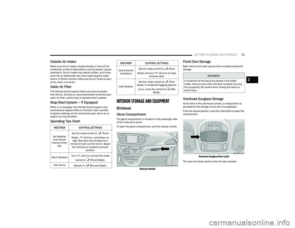
To open the glove compartment, pull the release handle.
Release Handle
Front Door Storage
Both interior front door panels have multiple pockets for
storage.
Overhead Sunglass Storage
At the front of the overhead console, a compartment is
provided for the storage of one pair of sunglasses.
From the closed position, push the indentation to open the
compartment.
Overhead Sunglass Door Latch
The door will slowly rotate to the full open position.
WEATHER CONTROL SETTINGS
Hot Weather
And Vehicle
Interior Is Very Hot Set the mode control to (Panel
Mode), (A/C) on, and blower on high. Roll down the windows for a
minute to flush out the hot air. Adjust the controls as needed to achieve comfort.
Warm Weather Turn (A/C) on and set the mode
control to (Panel Mode).
Cool Sunny Operate in (Bi-Level Mode).
Cool & Humid
Conditions Set the mode control to (Floor
Mode) and turn (A/C) on to keep windows clear.
Cold Weather Set the mode control to (Floor
Mode). If windshield fogging starts to
occur, move the control to (Mix Mode).
WEATHER CONTROL SETTINGS
WARNING!
If containers of hot liquid are placed in the bottle
holder, they can spill when the door is closed, burning
the occupants. Be careful when closing the doors to
avoid injury.2
23_RUP_OM_EN_USC_t.book Page 71
Page 79 of 328
GETTING TO KNOW YOUR VEHICLE77
POWER INVERTER — IF EQUIPPED
There is a 115 Volt, 150 W Power Inverter outlet located
on the right side of the vehicle, before the third row of
seats to convert DC current to AC current. The Power
Inverter can power cellular phones, electronics and other
low power devices requiring up to 150 W. Certain video
game consoles will exceed this power limit, as will most
power tools.
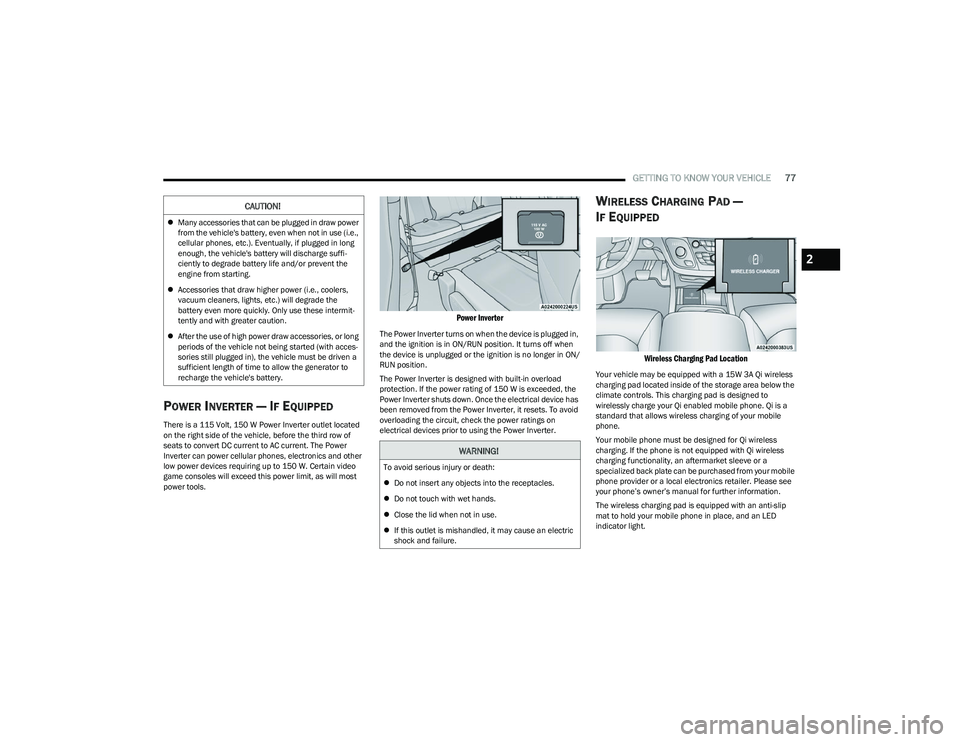
Power Inverter
The Power Inverter turns on when the device is plugged in,
and the ignition is in ON/RUN position. It turns off when
the device is unplugged or the ignition is no longer in ON/
RUN position.
The Power Inverter is designed with built-in overload
protection. If the power rating of 150 W is exceeded, the
Power Inverter shuts down. Once the electrical device has
been removed from the Power Inverter, it resets. To avoid
overloading the circuit, check the power ratings on
electrical devices prior to using the Power Inverter.
WIRELESS CHARGING PAD —
I
F EQUIPPED
Wireless Charging Pad Location
Your vehicle may be equipped with a 15W 3A Qi wireless
charging pad located inside of the storage area below the
climate controls. This charging pad is designed to
wirelessly charge your Qi enabled mobile phone. Qi is a
standard that allows wireless charging of your mobile
phone.
Your mobile phone must be designed for Qi wireless
charging. If the phone is not equipped with Qi wireless
charging functionality, an aftermarket sleeve or a
specialized back plate can be purchased from your mobile
phone provider or a local electronics retailer. Please see
your phone’s owner’s manual for further information.
The wireless charging pad is equipped with an anti-slip
mat to hold your mobile phone in place, and an LED
indicator light.
CAUTION!
Many accessories that can be plugged in draw power
from the vehicle's battery, even when not in use (i.e.,
cellular phones, etc.). Eventually, if plugged in long
enough, the vehicle's battery will discharge suffi -
ciently to degrade battery life and/or prevent the
engine from starting.
Accessories that draw higher power (i.e., coolers,
vacuum cleaners, lights, etc.) will degrade the
battery even more quickly. Only use these intermit -
tently and with greater caution.
After the use of high power draw accessories, or long
periods of the vehicle not being started (with acces -
sories still plugged in), the vehicle must be driven a
sufficient length of time to allow the generator to
recharge the vehicle's battery.
WARNING!
To avoid serious injury or death:
Do not insert any objects into the receptacles.
Do not touch with wet hands.
Close the lid when not in use.
If this outlet is mishandled, it may cause an electric
shock and failure.
2
23_RUP_OM_EN_USC_t.book Page 77
Page 80 of 328

78GETTING TO KNOW YOUR VEHICLE
LED Indicator Status:
No Light: Charging pad is idle or searching for a device.
Blue Light: Device is detected and is charging.
Red Light/Flashing: Internal error or foreign object is
detected.
Important Notes Regarding This Vehicle’s Wireless
Charging Pad:
The wireless charging pad will not work if any of the
four doors or the liftgate are open, even if the engine is
running.
Wireless charging is not as fast as when the phone is
connected to a wired charger.
The phone’s protective case must be removed when
placed on the wireless charging pad.
iPhone® 12 (including iPod®) is equipped with soft -
ware to protect the device from overheating. When the
software is active, the rate of charge is slowed down to
protect the device.
Phones must always be placed on the wireless
charging pad within the outline shown on the pad so
that its charging parts connect with the charging coils
of the system. Movement of the phone during charging
may prevent or slow the rate of charge.
Having multiple applications open on the phone while
charging will reduce the charging efficiency, and may
even shut down an application that is actively running
(i.e. Apple CarPlay®). This may also cause the phone to
overheat.
Wireless chargers may implement certain methods to
prevent the phone from overheating during charging
such as slowing down the rate of charge. In certain instances, the device may shut down for a brief period
of time (when the device reaches a certain tempera
-
ture). If this happens, it does not mean there is a fault
with the wireless charing pad. This may just be a
protective measure to prevent damage to the phone.
WINDOWS
POWER WINDOWS
The window switches on the driver’s door trim panel
control all of the door windows.
Driver’s Power Window Controls
The driver may lock out the rear power windows by
pushing the bar control just below the power window
controls.
Window Lockout Switch
The window switches will operate only when the ignition is
in the ACC or ON/RUN position and during power
accessory delay.
NOTE:Power Window controls will also remain active for up to
10 minutes after the ignition has been placed in the OFF
position, depending upon the accessory delay setting.
Opening a front door will cancel this feature.
There is a single control on the front passenger’s door trim
panel which operates the passenger door window and a
set of controls that lock and unlock all doors. The controls
will operate only when the ignition is in the ACC or ON/RUN
position and during power accessory delay.
CAUTION!
The key fob should not be placed on the charging pad
or within 6 inches (15 cm) of it. Doing so can cause
excessive heat buildup and damage to the fob. Placing
the fob in close proximity of the charging pad blocks the
fob from being detected by the vehicle and prevents the
vehicle from starting.
23_RUP_OM_EN_USC_t.book Page 78
Page 84 of 328

82GETTING TO KNOW YOUR VEHICLE
HOOD
OPENING
If applicable, refer to the “Hybrid Supplement” for
additional information.
The hood release lever (to open the primary latch) and
safety latch (to open the secondary latch) must be
released to open the hood.
1. Pull the hood release lever located under the
driver’s side of the instrument panel.
Hood Release Lever
2. Move to the outside of the front of the vehicle.
3. Push the safety latch release lever toward the passenger side of the vehicle. The safety latch is
located behind the center front edge of the hood.
Safety Latch Release Lever Location
4. Remove the support rod from the locking tab and insert it into the seat located on the underside of the
hood.
NOTE:
Before lifting the hood, check that the wiper arms are
not in motion and not in the lifted position.
While lifting the hood, use both hands.
Vehicle must be at a stop and the gear selector must
be in PARK.
CLOSING
If applicable, refer to the “Hybrid Supplement” for
additional information.
1. Hold up the hood with one hand and with the other
hand remove the support rod from its seat and
reinsert it into the locking tab.
2. Lower the hood to approximately 12 inches (30 cm) from the engine compartment and drop it. Make sure
that the hood is completely closed.
WARNING!
Be sure the hood is fully latched before driving your
vehicle. If the hood is not fully latched, it could open
when the vehicle is in motion and block your vision.
Failure to follow this warning could result in serious
injury or death.
CAUTION!
To prevent possible damage, do not slam the hood to
close it. Lower hood to approximately 12 inches (30 cm)
and drop the hood to close. Make sure hood is fully
closed for both latches. Never drive vehicle unless hood
is fully closed, with both latches engaged.
23_RUP_OM_EN_USC_t.book Page 82
Page 88 of 328
86GETTING TO KNOW YOUR VEHICLE
(Continued)
CARGO AREA FEATURES
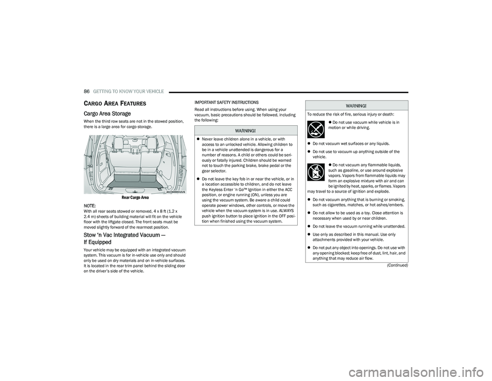
Cargo Area Storage
When the third row seats are not in the stowed position,
there is a large area for cargo storage.
Rear Cargo Area
NOTE:
With all rear seats stowed or removed, 4 x 8 ft (1.2 x
2.4 m) sheets of building material will fit on the vehicle
floor with the liftgate closed. The front seats must be
moved slightly forward of the rearmost position.
Stow ‘n Vac Integrated Vacuum —
If Equipped
Your vehicle may be equipped with an integrated vacuum
system. This vacuum is for in-vehicle use only and should
only be used on dry materials and on in-vehicle surfaces.
It is located in the rear trim panel behind the sliding door
on the driver’s side of the vehicle. IMPORTANT SAFETY INSTRUCTIONS
Read all instructions before using. When using your
vacuum, basic precautions should be followed, including
the following:
WARNING!
Never leave children alone in a vehicle, or with
access to an unlocked vehicle. Allowing children to
be in a vehicle unattended is dangerous for a
number of reasons. A child or others could be seri -
ously or fatally injured. Children should be warned
not to touch the parking brake, brake pedal or the
gear selector.
Do not leave the key fob in or near the vehicle, or in
a location accessible to children, and do not leave
the Keyless Enter ‘n Go™ Ignition in either the ACC
position, or engine running (ON), unless you are
using the vacuum system. Be aware a child could
operate power windows, other controls, or move the
vehicle when the vacuum system is in use. ALWAYS
push ignition button to place ignition in the OFF posi -
tion when finished using the vacuum system.
WARNING!
To reduce the risk of fire, serious injury or death:
Do not use vacuum while vehicle is in
motion or while driving.
Do not vacuum wet surfaces or any liquids.
Do not use to vacuum up anything outside of the
vehicle.
Do not vacuum any flammable liquids,
such as gasoline, or use around explosive
vapors. Vapors from flammable liquids may
form an explosive mixture with air and can
be ignited by heat, sparks, or flames. Vapors
may travel to a source of ignition and explode.
Do not vacuum anything that is burning or smoking,
such as cigarettes, matches, or hot ashes/embers.
Do not allow to be used as a toy. Close attention is
necessary when used by or near children.
Do not leave the vacuum running while unattended.
Use only as described in this manual. Use only
attachments provided with your vehicle.
Do not put any object into openings. Do not use with
any opening blocked; keep free of dust, lint, hair, and
anything that may reduce air flow.
23_RUP_OM_EN_USC_t.book Page 86
Page 89 of 328

GETTING TO KNOW YOUR VEHICLE87
(Continued)
The vacuum will operate in two modes:
Ignition in the ACC position: Engine remains off, and
vacuum usage is limited to 10 minutes.
Ignition in the START position: Engine is running, and
vacuum usage is unlimited until the vehicle’s battery
level falls below 60%.
NOTE:The vacuum will not operate when the ignition is in the OFF
position, or in the ON/RUN position with the engine off. For
more information on ignition positions, see
Úpage 15.
1. Before Using Vacuum:
Accessory (ACC) Mode Operation - For up to
10 minutes of operation
Always apply the parking brake, shift the transmission
into PARK, and push ignition button to place ignition in
Accessory (ACC) mode. The engine will not be running
in this mode. Do not leave the key fob in or near the ve -
hicle, or in a location accessible to children.
NOTE:The vacuum system will run for 10 minutes off battery
power and then the vacuum will shut down. A low battery
indication light (LOW PWR) located below the vacuum
nozzle storage location will come on one minute before
the vacuum shuts down.
Engine Running (START) Operation - For more than
10 minutes of operation
Position vehicle outdoors and fully open all side
windows.
Always apply the parking brake, shift the transmis -
sion into PARK, and leave engine running. 2. Unclip the vacuum nozzle and pull to extend vacuum
hose from the storage location.NOTE:The hose can reach every corner of the vehicle floor.
3. Install desired attachment if needed.
Front Storage Compartments
Do not vacuum toxic material such as chlorine
bleach, ammonia, drain cleaner, etc.
Do not vacuum hard or sharp objects such as glass,
nails, screws, coins, etc.
Keep hair, loose clothing, fingers, and all parts of
body away from openings and moving parts.
Only use with filter in place. Periodically check that
the filter is in place and in good condition.
WARNING!
This equipment incorporates parts such as switches,
motors, or the like that tend to produce arcs or sparks
that can cause an explosion. When using your vacuum
near gasoline-dispensing equipment or service
stations, park vehicle at least 20 ft (6 m) away from the
exterior enclosure of any dispensing pump. The vacuum
is mounted more than 18 inches (45 cm) above ground
level in your vehicle.
WARNING!
WARNING!
Carbon monoxide (CO) in exhaust gases can cause
serious injury or death. Follow these precautions to
prevent carbon monoxide poisoning:
Do not inhale exhaust gases.
Do not start or run an engine in a closed garage or
confined area. Always position vehicle outdoors and
fully open all side windows before using vacuum
system with the engine running.
Guard against carbon monoxide with proper mainte -
nance. Have the exhaust system inspected every
time the vehicle is raised. Have any abnormal condi -
tions repaired promptly.
1 — Vacuum Nozzle Storage Location
2 — Attachment Compartment
WARNING!
2
23_RUP_OM_EN_USC_t.book Page 87