2023 CHRYSLER PACIFICA HYBRID door lock
[x] Cancel search: door lockPage 60 of 328

58GETTING TO KNOW YOUR VEHICLE
INTERIOR LIGHTS
INTERIOR COURTESY LIGHTS
The courtesy light switches are used to turn the courtesy
lights on/off.
Courtesy Light Switches
To operate the courtesy lights, push either the driver or
passenger light switch.
NOTE:
Before exiting the vehicle, make sure that the interior
lights are turned off. This will prevent the battery from
discharging once the doors are closed.
If a light is left on, it will automatically be turned off
approximately 10 minutes after the ignition is placed in
the OFF position.
Rear Courtesy/Reading Lights —
If Equipped
Located above the rear passengers are courtesy/reading
lights. The lights turn on when a front door, a sliding door
or the liftgate is opened. If your vehicle is equipped with
Remote Keyless Entry (RKE) the lights will also turn on
when the unlock button on the key fob is pushed.
The courtesy lights also function as reading lights. Push
the lens to turn these lights on while inside the vehicle.
Push the lens a second time to turn each light off.
Dimmer Controls
The dimmer controls are part of the headlight switch, and
are located on the driver’s side of the instrument panel.
With the parking lights or headlights on, rotating the right
dimmer control upward will increase the brightness of the
instrument cluster lights. Rotating the left dimmer control
will adjust the interior light levels of the ambient lighting
on the instrument panel and doors.
Dimmer Controls
Dimmer Controls (Vehicles Sold In Canada Only)
1 — Ambient Light Dimmer Control
2 — Instrument Panel Dimmer Control
1 — Ambient Light Dimmer Control
2 — Instrument Panel Dimmer Control
23_RUP_OM_EN_USC_t.book Page 58
Page 80 of 328

78GETTING TO KNOW YOUR VEHICLE
LED Indicator Status:
No Light: Charging pad is idle or searching for a device.
Blue Light: Device is detected and is charging.
Red Light/Flashing: Internal error or foreign object is
detected.
Important Notes Regarding This Vehicle’s Wireless
Charging Pad:
The wireless charging pad will not work if any of the
four doors or the liftgate are open, even if the engine is
running.
Wireless charging is not as fast as when the phone is
connected to a wired charger.
The phone’s protective case must be removed when
placed on the wireless charging pad.
iPhone® 12 (including iPod®) is equipped with soft -
ware to protect the device from overheating. When the
software is active, the rate of charge is slowed down to
protect the device.
Phones must always be placed on the wireless
charging pad within the outline shown on the pad so
that its charging parts connect with the charging coils
of the system. Movement of the phone during charging
may prevent or slow the rate of charge.
Having multiple applications open on the phone while
charging will reduce the charging efficiency, and may
even shut down an application that is actively running
(i.e. Apple CarPlay®). This may also cause the phone to
overheat.
Wireless chargers may implement certain methods to
prevent the phone from overheating during charging
such as slowing down the rate of charge. In certain instances, the device may shut down for a brief period
of time (when the device reaches a certain tempera
-
ture). If this happens, it does not mean there is a fault
with the wireless charing pad. This may just be a
protective measure to prevent damage to the phone.
WINDOWS
POWER WINDOWS
The window switches on the driver’s door trim panel
control all of the door windows.
Driver’s Power Window Controls
The driver may lock out the rear power windows by
pushing the bar control just below the power window
controls.
Window Lockout Switch
The window switches will operate only when the ignition is
in the ACC or ON/RUN position and during power
accessory delay.
NOTE:Power Window controls will also remain active for up to
10 minutes after the ignition has been placed in the OFF
position, depending upon the accessory delay setting.
Opening a front door will cancel this feature.
There is a single control on the front passenger’s door trim
panel which operates the passenger door window and a
set of controls that lock and unlock all doors. The controls
will operate only when the ignition is in the ACC or ON/RUN
position and during power accessory delay.
CAUTION!
The key fob should not be placed on the charging pad
or within 6 inches (15 cm) of it. Doing so can cause
excessive heat buildup and damage to the fob. Placing
the fob in close proximity of the charging pad blocks the
fob from being detected by the vehicle and prevents the
vehicle from starting.
23_RUP_OM_EN_USC_t.book Page 78
Page 81 of 328
GETTING TO KNOW YOUR VEHICLE79
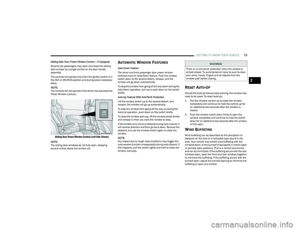
Sliding Side Door Power Window Control — If Equipped
Second row passengers may open and close the sliding
door window by a single control on the door handle
assembly.
The controls will operate only when the ignition switch is in
the ACC or ON/RUN position and during power accessory
delay.
NOTE:The controls will not operate if the driver has activated the
Power Window Lockout.
Sliding Door Power Window Control (Left Side Shown)
NOTE:
The sliding door windows do not fully open, stopping
several inches above the window sill.
AUTOMATIC WINDOW FEATURES
Auto-Down Feature
The driver and front passenger door power window
switches have an Auto-Down feature. Push the window
switch down to the second detent, release, and the
window will go down automatically.
To stop the window from going all the way down during the
Auto-Down operation, pull up or push down on the switch
briefly.
Auto-Up Feature With Anti-Pinch Protection
Lift the window switch up to the second detent, and
release; the window will go up automatically.
To stop the window from going all the way up during the
Auto-Up operation, push down on the switch briefly.
To close the window part way, lift the window switch briefly
and release it when you want the window to stop.
If the window runs into any obstacle during auto-closure, it
will reverse direction and then go back down. Remove the
obstacle and use the window switch again to close the
window.
NOTE:Any impact due to rough road conditions may trigger the
auto-reverse function unexpectedly during auto-closure. If
this happens, pull the switch lightly and hold to close the
window manually.
RESET AUTO-UP
Should the Auto-Up feature stop working, the window may
need to be reset. To reset Auto-Up:
1. Pull the window control up to close the window completely and continue to hold the control up for
an additional two seconds after the window is
closed.
2. Push the window switch down firmly to open the window completely and continue to hold the switch
down for an additional two seconds after the window
is fully open.
WIND BUFFETING
Wind buffeting can be described as the perception of
pressure on the ears or a helicopter-type sound in the
ears. Your vehicle may exhibit wind buffeting with the
windows down, or the sunroof (if equipped) in certain open
or partially open positions. This is a normal occurrence
and can be minimized. If the buffeting occurs with the rear
windows open, open the front and rear windows together
to minimize the buffeting. If the buffeting occurs with the
sunroof open, adjust the sunroof opening to minimize the
buffeting or open any window.
WARNING!
There is no anti-pinch protection when the window is
almost closed. To avoid personal injury be sure to clear
your arms, hands, fingers and all objects from the
window path before closing.
2
23_RUP_OM_EN_USC_t.book Page 79
Page 85 of 328
GETTING TO KNOW YOUR VEHICLE83
LIFTGATE
TO UNLOCK/OPEN THE LIFTGATE
The liftgate may be released in several ways:
Key fob
Liftgate Release Handle
Button on overhead console
Push the liftgate button on the key fob twice within five
seconds to release the liftgate.
The key fob and the overhead console button will release
the liftgate when the liftgate is locked. The outside handle
requires the liftgate to be unlocked. If the vehicle is
equipped with Passive Entry, pulling the electronic liftgate
release handle will unlock and release the liftgate, with a
valid Passive Entry key fob within 5 ft (1.5 m) of the
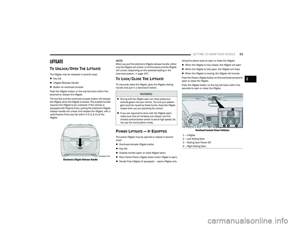
liftgate.
Electronic Liftgate Release Handle
NOTE:
When you pull the electronic liftgate release handle, either
only the liftgate will unlock, or all the doors and the liftgate
will unlock, depending on the selected setting in the
Uconnect system
Úpage 157.
TO LOCK/CLOSE THE LIFTGATE
To manually close the liftgate, grab the liftgate closing
handle and pull in a downward motion.
POWER LIFTGATE — IF EQUIPPED
The power liftgate may be opened or closed in several
ways:
Overhead console liftgate button
Key fob
Outside handle (open or reset liftgate latch)
Rear Interior Power Liftgate button (when liftgate is open)
Hands-Free Liftgate (if equipped) — opens liftgate only Using the above ways to open or close the liftgate:
When the liftgate is fully closed, the liftgate will open
When the liftgate is fully open, the liftgate will close
When the liftgate is moving, the liftgate will reverse
Push the Power Liftgate button on the overhead console to
open or close the liftgate.
Push the liftgate button on the key fob twice within five
seconds to open or close the liftgate.
Overhead Console Power Switches
WARNING!
Driving with the liftgate open can allow poisonous
exhaust gases into your vehicle. You and your passen -
gers could be injured by these fumes. Keep the liftgate
closed when you are operating the vehicle.
If you are required to drive with the liftgate open,
make sure that all windows are closed, and the
climate control blower switch is set at high speed. Do
not use the recirculation mode.
1 — Liftgate
2 — Left Sliding Door
3 — Sliding Door Power Off
4 — Right Sliding Door
2
23_RUP_OM_EN_USC_t.book Page 83
Page 86 of 328
84GETTING TO KNOW YOUR VEHICLE
The key fob and the overhead console button will operate
the liftgate when the liftgate is locked. The outside handle
requires the liftgate to be unlocked. If the vehicle is
equipped with Passive Entry, pressing the touch pad on
the outside handle or Hands-Free Liftgate foot activation
(if equipped) will unlock and open the liftgate, with a valid
Passive Entry key fob within 5 ft (1.5 m) of the liftgate
handle.
NOTE:
To open the liftgate, the Hands-Free Liftgate foot acti -
vation (if equipped) requires a valid Passive Entry key
fob within 5 ft (1.5 m) of the door handle.
When you pull the electronic liftgate release handle,
either only the liftgate will unlock, or all the doors and
the liftgate will unlock, depending on the selected
setting in the Uconnect system.
Tones are sounded and the turn signals are flashed
with liftgate movements. These alerts can be turned on
or off in Uconnect Settings
Úpage 157. To Close The Liftgate
The liftgate can also be closed using the Rear Interior
Power Liftgate button (if equipped), located in the upper
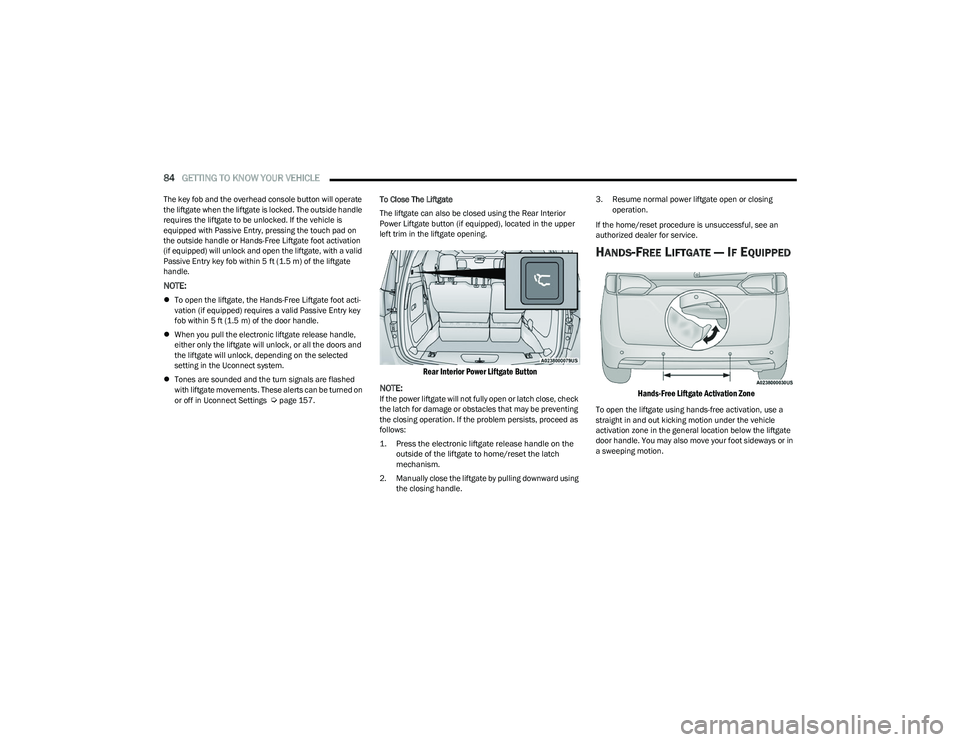
left trim in the liftgate opening.
Rear Interior Power Liftgate Button
NOTE:
If the power liftgate will not fully open or latch close, check
the latch for damage or obstacles that may be preventing
the closing operation. If the problem persists, proceed as
follows:
1. Press the electronic liftgate release handle on the outside of the liftgate to home/reset the latch
mechanism.
2. Manually close the liftgate by pulling downward using the closing handle. 3. Resume normal power liftgate open or closing
operation.
If the home/reset procedure is unsuccessful, see an
authorized dealer for service.
HANDS-FREE LIFTGATE — IF EQUIPPED
Hands-Free Liftgate Activation Zone
To open the liftgate using hands-free activation, use a
straight in and out kicking motion under the vehicle
activation zone in the general location below the liftgate
door handle. You may also move your foot sideways or in
a sweeping motion.
23_RUP_OM_EN_USC_t.book Page 84
Page 88 of 328
86GETTING TO KNOW YOUR VEHICLE
(Continued)
CARGO AREA FEATURES
Cargo Area Storage
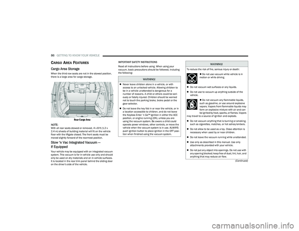
When the third row seats are not in the stowed position,
there is a large area for cargo storage.
Rear Cargo Area
NOTE:
With all rear seats stowed or removed, 4 x 8 ft (1.2 x
2.4 m) sheets of building material will fit on the vehicle
floor with the liftgate closed. The front seats must be
moved slightly forward of the rearmost position.
Stow ‘n Vac Integrated Vacuum —
If Equipped
Your vehicle may be equipped with an integrated vacuum
system. This vacuum is for in-vehicle use only and should
only be used on dry materials and on in-vehicle surfaces.
It is located in the rear trim panel behind the sliding door
on the driver’s side of the vehicle. IMPORTANT SAFETY INSTRUCTIONS
Read all instructions before using. When using your
vacuum, basic precautions should be followed, including
the following:
WARNING!
Never leave children alone in a vehicle, or with
access to an unlocked vehicle. Allowing children to
be in a vehicle unattended is dangerous for a
number of reasons. A child or others could be seri -
ously or fatally injured. Children should be warned
not to touch the parking brake, brake pedal or the
gear selector.
Do not leave the key fob in or near the vehicle, or in
a location accessible to children, and do not leave
the Keyless Enter ‘n Go™ Ignition in either the ACC
position, or engine running (ON), unless you are
using the vacuum system. Be aware a child could
operate power windows, other controls, or move the
vehicle when the vacuum system is in use. ALWAYS
push ignition button to place ignition in the OFF posi -
tion when finished using the vacuum system.
WARNING!
To reduce the risk of fire, serious injury or death:
Do not use vacuum while vehicle is in
motion or while driving.
Do not vacuum wet surfaces or any liquids.
Do not use to vacuum up anything outside of the
vehicle.
Do not vacuum any flammable liquids,
such as gasoline, or use around explosive
vapors. Vapors from flammable liquids may
form an explosive mixture with air and can
be ignited by heat, sparks, or flames. Vapors
may travel to a source of ignition and explode.
Do not vacuum anything that is burning or smoking,
such as cigarettes, matches, or hot ashes/embers.
Do not allow to be used as a toy. Close attention is
necessary when used by or near children.
Do not leave the vacuum running while unattended.
Use only as described in this manual. Use only
attachments provided with your vehicle.
Do not put any object into openings. Do not use with
any opening blocked; keep free of dust, lint, hair, and
anything that may reduce air flow.
23_RUP_OM_EN_USC_t.book Page 86
Page 91 of 328
GETTING TO KNOW YOUR VEHICLE89
5. When finished, push power button to turn vacuum off
and store vacuum hose and any attachments.
6. Before exiting the vehicle: If the ignition is in the ACC position, push the
START/STOP ignition button to place ignition in the
OFF position, remove key fob from the vehicle, and
lock the vehicle.
If the engine is running, raise all of the windows,
push the START/STOP ignition button to place igni -
tion in the OFF position, remove key fob from the
vehicle, close all of the doors and the liftgate and
lock the vehicle.
Vacuum Troubleshooting
DO NOT use with any opening blocked. If an object
becomes lodged in the hose, attempt to fully extend
the hose in a straight line while the vacuum motor is
running. If this does not dislodge the object, turn the
vacuum OFF and remove the hose from the vehicle
using the subsequent removal instructions. If the filter
is clogged, follow the emptying debris bin procedure
and lightly tap the filter on the collection bin to remove any collected debris from the filter. Both the bin and
the filter can be rinsed with water if needed. To avoid
mold and stale odors, allow both to dry completely
before reinstalling in your vehicle. If the filter has tears,
holes or other damage and needs to be replaced,
please contact an authorized dealer.
If there are any other issues with your vacuum, contact
an authorized dealer. Your vacuum has no user
serviceable parts.
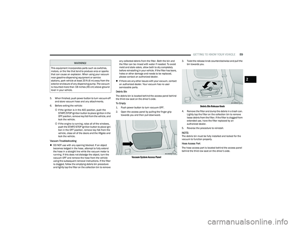
Debris Bin
The debris bin is located behind the access panel behind
the third row seat on the driver’s side.
To Empty
1. Push power button to turn vacuum OFF.
2. Open the access panel by pulling the finger grip towards you and then pull downward.
Vacuum System Access Panel
3. Twist the release knob counterclockwise and pull the bin towards you.
Debris Bin Release Knob
4. Remove the filter and dump the debris in a trash can. Lightly tap the filter on the collection bin to remove
loose debris from the filter. If the filter is clogged from
extended use, have the filter replaced by an
authorized dealer.
5. Reverse the procedure to reinstall.
NOTE:The debris bin must be fully installed and locked for the
vacuum to function properly.
Hose Access Port
The hose access port is located behind the access panel
behind the third row seat on the driver’s side.
WARNING!
This equipment incorporates parts such as switches,
motors, or the like that tend to produce arcs or sparks
that can cause an explosion. When using your vacuum
near gasoline-dispensing equipment or service
stations, park vehicle at least 20 ft (6 m) away from the
exterior enclosure of any dispensing pump. The vacuum
is mounted more than 18 inches (45 cm) above ground
level in your vehicle.
2
23_RUP_OM_EN_USC_t.book Page 89
Page 105 of 328
GETTING TO KNOW YOUR INSTRUMENT PANEL103
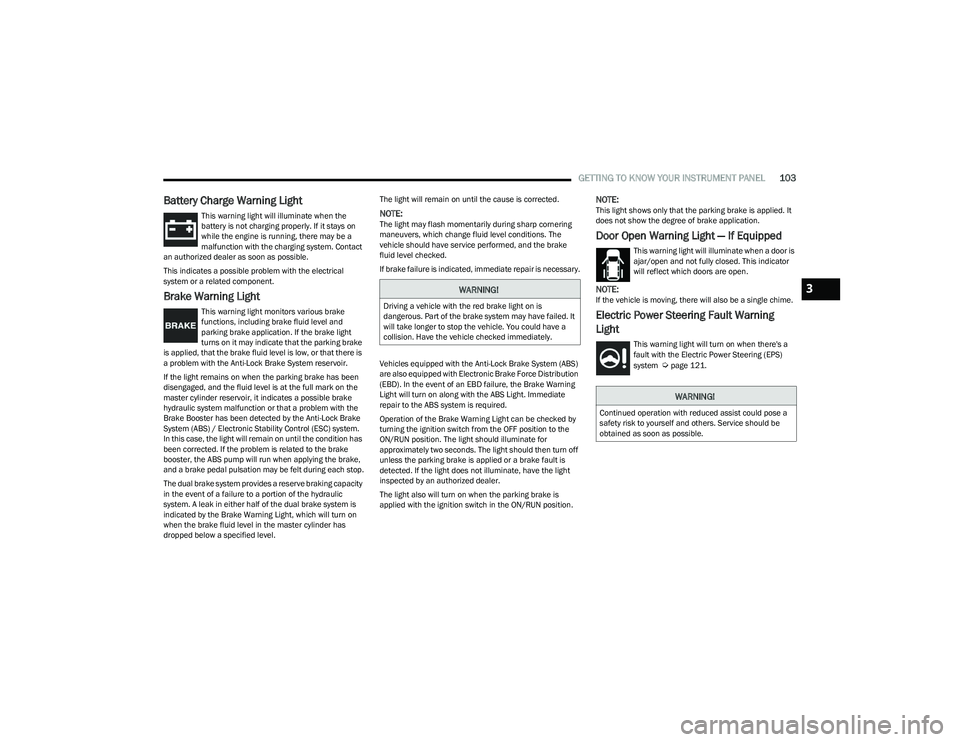
Battery Charge Warning Light
This warning light will illuminate when the
battery is not charging properly. If it stays on
while the engine is running, there may be a
malfunction with the charging system. Contact
an authorized dealer as soon as possible.
This indicates a possible problem with the electrical
system or a related component.
Brake Warning Light
This warning light monitors various brake
functions, including brake fluid level and
parking brake application. If the brake light
turns on it may indicate that the parking brake
is applied, that the brake fluid level is low, or that there is
a problem with the Anti-Lock Brake System reservoir.
If the light remains on when the parking brake has been
disengaged, and the fluid level is at the full mark on the
master cylinder reservoir, it indicates a possible brake
hydraulic system malfunction or that a problem with the
Brake Booster has been detected by the Anti-Lock Brake
System (ABS) / Electronic Stability Control (ESC) system.
In this case, the light will remain on until the condition has
been corrected. If the problem is related to the brake
booster, the ABS pump will run when applying the brake,
and a brake pedal pulsation may be felt during each stop.
The dual brake system provides a reserve braking capacity
in the event of a failure to a portion of the hydraulic
system. A leak in either half of the dual brake system is
indicated by the Brake Warning Light, which will turn on
when the brake fluid level in the master cylinder has
dropped below a specified level. The light will remain on until the cause is corrected.
NOTE:The light may flash momentarily during sharp cornering
maneuvers, which change fluid level conditions. The
vehicle should have service performed, and the brake
fluid level checked.
If brake failure is indicated, immediate repair is necessary.
Vehicles equipped with the Anti-Lock Brake System (ABS)
are also equipped with Electronic Brake Force Distribution
(EBD). In the event of an EBD failure, the Brake Warning
Light will turn on along with the ABS Light. Immediate
repair to the ABS system is required.
Operation of the Brake Warning Light can be checked by
turning the ignition switch from the OFF position to the
ON/RUN position. The light should illuminate for
approximately two seconds. The light should then turn off
unless the parking brake is applied or a brake fault is
detected. If the light does not illuminate, have the light
inspected by an authorized dealer.
The light also will turn on when the parking brake is
applied with the ignition switch in the ON/RUN position.
NOTE:This light shows only that the parking brake is applied. It
does not show the degree of brake application.
Door Open Warning Light — If Equipped
This warning light will illuminate when a door is
ajar/open and not fully closed. This indicator
will reflect which doors are open.
NOTE:If the vehicle is moving, there will also be a single chime.
Electric Power Steering Fault Warning
Light
This warning light will turn on when there's a
fault with the Electric Power Steering (EPS)
system
Úpage 121.
WARNING!
Driving a vehicle with the red brake light on is
dangerous. Part of the brake system may have failed. It
will take longer to stop the vehicle. You could have a
collision. Have the vehicle checked immediately.
WARNING!
Continued operation with reduced assist could pose a
safety risk to yourself and others. Service should be
obtained as soon as possible.
3
23_RUP_OM_EN_USC_t.book Page 103