2023 CHRYSLER PACIFICA HYBRID fuel
[x] Cancel search: fuelPage 98 of 328
96GETTING TO KNOW YOUR INSTRUMENT PANEL
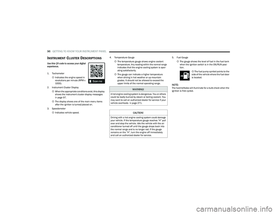
INSTRUMENT CLUSTER DESCRIPTIONS
Use this QR code to access your digital
experience.
1. Tachometer
Indicates the engine speed in
revolutions per minute (RPM x
1000).
2. Instrument Cluster Display When the appropriate conditions exist, this display
shows the instrument cluster display messages
Úpage 97.
The display shows one of the main menu items
after the ignition is turned/placed on.
3. Speedometer Indicates vehicle speed. 4. Temperature Gauge
The temperature gauge shows engine coolant
temperature. Any reading within the normal range
indicates that the engine cooling system is oper -
ating satisfactorily.
The gauge can indicate a higher temperature
when driving in hot weather or up mountain
grades. It should not be allowed to exceed the
upper limits of the normal operating range. 5. Fuel Gauge
The gauge shows the level of fuel in the fuel tank
when the ignition switch is in the ON/RUN posi -
tion.
The fuel pump symbol points to the
side of the vehicle where the fuel door
is located.
NOTE:The hard telltales will illuminate for a bulb check when the
ignition is first cycled.WARNING!
A hot engine cooling system is dangerous. You or others
could be badly burned by steam or boiling coolant. You
may want to call an authorized dealer for service if your
vehicle overheats
Úpage 271.
CAUTION!
Driving with a hot engine cooling system could damage
your vehicle. If the temperature gauge reaches “H” pull
over and stop the vehicle. Idle the vehicle with the air
conditioner turned off until the gauge drops back into
the normal range and is no longer red. If the gauge
remains on the “H”, turn the engine off immediately
and call an authorized dealer for service.
23_RUP_OM_EN_USC_t.book Page 96
Page 101 of 328
GETTING TO KNOW YOUR INSTRUMENT PANEL99
INSTRUMENT CLUSTER DISPLAY MENU
I
TEMS
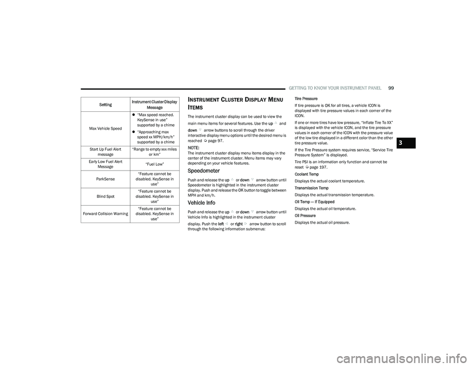
The instrument cluster display can be used to view the
main menu items for several features. Use the up and
down arrow buttons to scroll through the driver
interactive display menu options until the desired menu is
reached
Úpage 97.
NOTE:The instrument cluster display menu items display in the
center of the instrument cluster. Menu items may vary
depending on your vehicle features.
Speedometer
Push and release the up or down arrow button until
Speedometer is highlighted in the instrument cluster
display. Push and release the OK button to toggle between
MPH and km/h.
Vehicle Info
Push and release the up or down arrow button until
Vehicle Info is highlighted in the instrument cluster
display. Push the left or right arrow button to scroll
through the following information submenus: Tire Pressure
If tire pressure is
OK for all tires, a vehicle ICON is
displayed with tire pressure values in each corner of the
ICON.
If one or more tires have low pressure, “Inflate Tire To XX”
is displayed with the vehicle ICON, and the tire pressure
values in each corner of the ICON with the pressure value
of the low tire displayed in a different color than the other
tire pressure value.
If the Tire Pressure system requires service, “Service Tire
Pressure System” is displayed.
Tire PSI is an information only function and cannot be
reset
Úpage 197.
Coolant Temp
Displays the actual coolant temperature.
Transmission Temp
Displays the actual transmission temperature.
Oil Temp — If Equipped
Displays the actual oil temperature.
Oil Pressure
Displays the actual oil pressure.
Max Vehicle Speed
“Max speed reached.
KeySense in use”
supported by a chime
“Approaching max
speed xx MPH/km/h”
supported by a chime
Start Up Fuel Alert message “Range to empty xxx miles
or km”
Early Low Fuel Alert Message “Fuel Low”
ParkSense “Feature cannot be
disabled. KeySense in use”
Blind Spot “Feature cannot be
disabled. KeySense in use”
Forward Collision Warning “Feature cannot be
disabled. KeySense in use”
Setting
Instrument Cluster Display
Message
3
23_RUP_OM_EN_USC_t.book Page 99
Page 102 of 328
100GETTING TO KNOW YOUR INSTRUMENT PANEL
Oil Life
Displays the remaining engine oil life as a percentage.
To reset the Oil Life, you must hold the OK button. The
“Hold OK to Reset” instruction will be displayed at all
times, but the following conditions will need to be met in
order to reset Oil Life:
The ignition must be in the ON/RUN position.
If the conditions are met, holding the OK button will reset
the gauge and the numeric display will return to 100%.
If the conditions are not met, a pop-up message will
display for five seconds, describing the required
conditions, and then the Oil Life screen will reappear.
Battery Voltage
Displays the actual battery voltage.
Engine Hours — If Equipped
Displays the number of hours of engine operation.
Driver Assist — If Equipped
Push and release the up or down arrow button until
the Driver Assist display icon is highlighted in the
instrument cluster display.
Adaptive Cruise Control
LaneSense
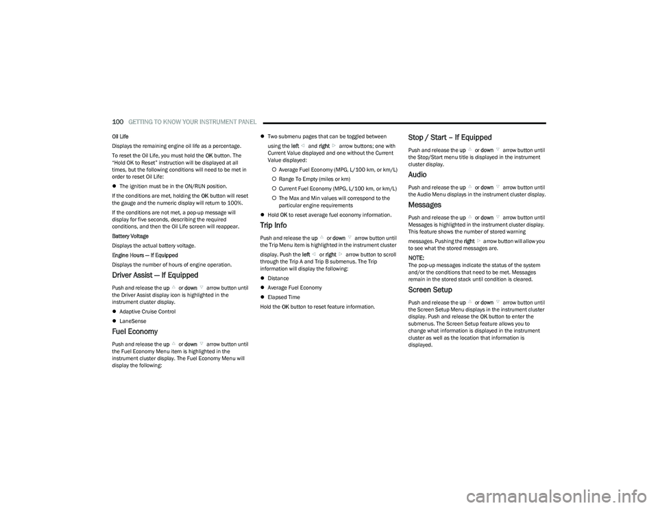
Fuel Economy
Push and release the up or down arrow button until
the Fuel Economy Menu item is highlighted in the
instrument cluster display. The Fuel Economy Menu will
display the following:
Two submenu pages that can be toggled between
using the left and right arrow buttons; one with
Current Value displayed and one without the Current
Value displayed:
Average Fuel Economy (MPG, L/100 km, or km/L)
Range To Empty (miles or km)
Current Fuel Economy (MPG, L/100 km, or km/L)
The Max and Min values will correspond to the
particular engine requirements
Hold OK to reset average fuel economy information.
Trip Info
Push and release the up or down arrow button until
the Trip Menu item is highlighted in the instrument cluster
display. Push the left or right arrow button to scroll
through the Trip A and Trip B submenus. The Trip
information will display the following:
Distance
Average Fuel Economy
Elapsed Time
Hold the OK button to reset feature information.
Stop / Start – If Equipped
Push and release the up or down arrow button until
the Stop/Start menu title is displayed in the instrument
cluster display.
Audio
Push and release the up or down arrow button until
the Audio Menu displays in the instrument cluster display.
Messages
Push and release the up or down arrow button until
Messages is highlighted in the instrument cluster display.
This feature shows the number of stored warning
messages. Pushing the right arrow button will allow you
to see what the stored messages are.
NOTE:The pop-up messages indicate the status of the system
and/or the conditions that need to be met. Messages
remain in the stored stack until condition is cleared.
Screen Setup
Push and release the up or down arrow button until
the Screen Setup Menu displays in the instrument cluster
display. Push and release the OK button to enter the
submenus. The Screen Setup feature allows you to
change what information is displayed in the instrument
cluster as well as the location that information is
displayed.
23_RUP_OM_EN_USC_t.book Page 100
Page 107 of 328
GETTING TO KNOW YOUR INSTRUMENT PANEL105
Vehicle Security Warning Light —
If Equipped
This warning light will flash at a fast rate for
approximately 15 seconds when the vehicle
security system is arming, and then will flash
slowly until the vehicle is disarmed.
YELLOW WARNING LIGHTS
Adaptive Cruise Control (ACC) Fault
Warning Light — If Equipped
This warning light will illuminate to indicate a
fault in the ACC system. Contact a local
authorized dealer for service
Úpage 124.
Electric Park Brake Warning Light
This warning light will illuminate to indicate the
Electric Park Brake is not functioning properly
and service is required. Contact an authorized
dealer.
Anti-Lock Brake System (ABS) Warning
Light
This warning light monitors the ABS. The light
will turn on when the ignition is placed in the
ON/RUN or ACC/ON/RUN position and may
stay on for as long as four seconds.
If the ABS light remains on or turns on while driving, then
the Anti-Lock portion of the brake system is not
functioning and service is required as soon as possible.
However, the conventional brake system will continue to
operate normally, assuming the Brake Warning Light is not
also on.
If the ABS light does not turn on when the ignition is placed
in the ON/RUN or ACC/ON/RUN position, have the brake
system inspected by an authorized dealer.
Electronic Stability Control (ESC) Active
Warning Light — If Equipped
This warning light will indicate when the ESC
system is Active. The ESC Indicator Light in the
instrument cluster will come on when the
ignition is placed in the ON/RUN or ACC/ON/
RUN position, and when ESC is activated. It should go out
with the engine running. If the ESC Indicator Light comes
on continuously with the engine running, a malfunction
has been detected in the ESC system. If this warning light
remains on after several ignition cycles, and the vehicle
has been driven several miles (kilometers) at speeds
greater than 30 mph (48 km/h), see an authorized dealer
as soon as possible to have the problem diagnosed and
corrected.
The ESC OFF Indicator Light and the ESC Indicator Light
come on momentarily each time the ignition is placed
in the ON/RUN or ACC/ON/RUN position.
The ESC system will make buzzing or clicking sounds
when it is active. This is normal; the sounds will stop
when ESC becomes inactive.
This light will come on when the vehicle is in an ESC
event.
Electronic Stability Control (ESC) OFF
Warning Light — If Equipped
This warning light indicates the ESC is off.
Each time the ignition is turned to ON/RUN or
ACC/ON/RUN, the ESC system will be on, even
if it was turned off previously.
LaneSense Warning Light — If Equipped
The LaneSense Warning Light will be solid
yellow when the vehicle is approaching a lane
marker. The warning light will flash when the
vehicle is crossing the lane marker
Úpage 140.
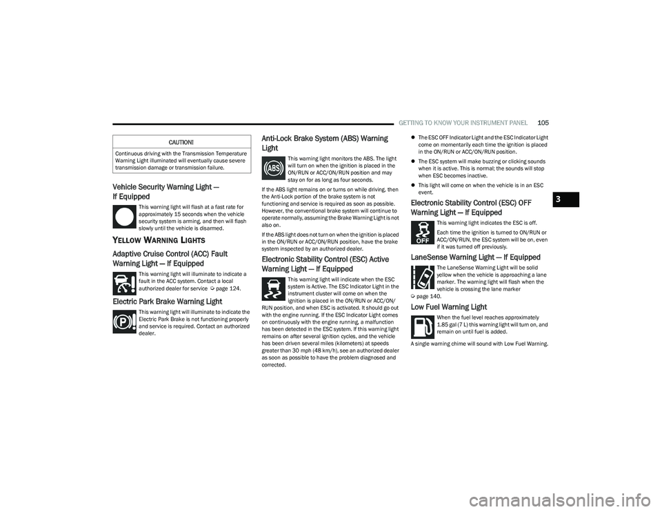
Low Fuel Warning Light
When the fuel level reaches approximately
1.85 gal (7 L) this warning light will turn on, and
remain on until fuel is added.
A single warning chime will sound with Low Fuel Warning.
CAUTION!
Continuous driving with the Transmission Temperature
Warning Light illuminated will eventually cause severe
transmission damage or transmission failure.
3
23_RUP_OM_EN_USC_t.book Page 105
Page 108 of 328
106GETTING TO KNOW YOUR INSTRUMENT PANEL
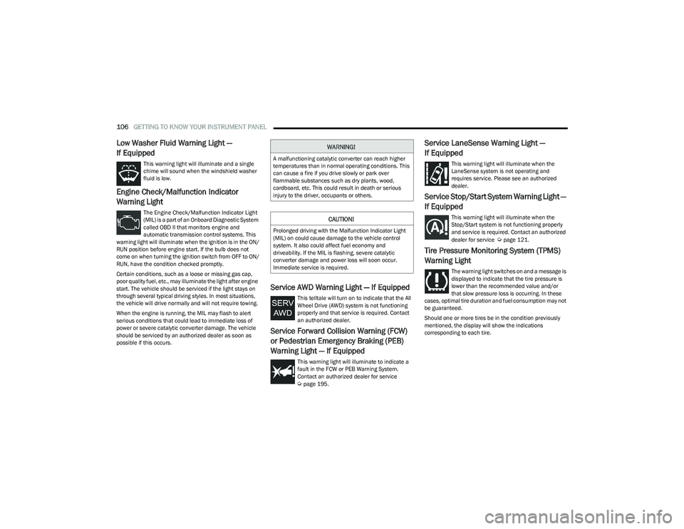
Low Washer Fluid Warning Light —
If Equipped
This warning light will illuminate and a single
chime will sound when the windshield washer
fluid is low.
Engine Check/Malfunction Indicator
Warning Light
The Engine Check/Malfunction Indicator Light
(MIL) is a part of an Onboard Diagnostic System
called OBD II that monitors engine and
automatic transmission control systems. This
warning light will illuminate when the ignition is in the ON/
RUN position before engine start. If the bulb does not
come on when turning the ignition switch from OFF to ON/
RUN, have the condition checked promptly.
Certain conditions, such as a loose or missing gas cap,
poor quality fuel, etc., may illuminate the light after engine
start. The vehicle should be serviced if the light stays on
through several typical driving styles. In most situations,
the vehicle will drive normally and will not require towing.
When the engine is running, the MIL may flash to alert
serious conditions that could lead to immediate loss of
power or severe catalytic converter damage. The vehicle
should be serviced by an authorized dealer as soon as
possible if this occurs.
Service AWD Warning Light — If Equipped
This telltale will turn on to indicate that the All
Wheel Drive (AWD) system is not functioning
properly and that service is required. Contact
an authorized dealer.
Service Forward Collision Warning (FCW)
or Pedestrian Emergency Braking (PEB)
Warning Light — If Equipped
This warning light will illuminate to indicate a
fault in the FCW or PEB Warning System.
Contact an authorized dealer for service
Úpage 195.
Service LaneSense Warning Light —
If Equipped
This warning light will illuminate when the
LaneSense system is not operating and
requires service. Please see an authorized
dealer.
Service Stop/Start System Warning Light —
If Equipped
This warning light will illuminate when the
Stop/Start system is not functioning properly
and service is required. Contact an authorized
dealer for service
Úpage 121.
Tire Pressure Monitoring System (TPMS)
Warning Light
The warning light switches on and a message is
displayed to indicate that the tire pressure is
lower than the recommended value and/or
that slow pressure loss is occurring. In these
cases, optimal tire duration and fuel consumption may not
be guaranteed.
Should one or more tires be in the condition previously
mentioned, the display will show the indications
corresponding to each tire.
WARNING!
A malfunctioning catalytic converter can reach higher
temperatures than in normal operating conditions. This
can cause a fire if you drive slowly or park over
flammable substances such as dry plants, wood,
cardboard, etc. This could result in death or serious
injury to the driver, occupants or others.
CAUTION!
Prolonged driving with the Malfunction Indicator Light
(MIL) on could cause damage to the vehicle control
system. It also could affect fuel economy and
driveability. If the MIL is flashing, severe catalytic
converter damage and power loss will soon occur.
Immediate service is required.
23_RUP_OM_EN_USC_t.book Page 106
Page 109 of 328

GETTING TO KNOW YOUR INSTRUMENT PANEL107
Each tire, including the spare (if provided), should be
checked monthly when cold and inflated to the inflation
pressure recommended by the vehicle manufacturer on
the vehicle placard or tire inflation pressure label. If your
vehicle has tires of a different size than the size indicated
on the vehicle placard or tire inflation pressure label, you
should determine the proper tire inflation pressure for
those tires.
As an added safety feature, your vehicle has been
equipped with a TPMS that illuminates a low tire pressure
telltale when one or more of your tires is significantly
underinflated. Accordingly, when the low tire pressure
telltale illuminates, you should stop and check your tires
as soon as possible, and inflate them to the proper
pressure. Driving on a significantly underinflated tire
causes the tire to overheat and can lead to tire failure.
Underinflation also reduces fuel efficiency and tire tread
life, and may affect the vehicle’s handling and stopping
ability.
Please note that the TPMS is not a substitute for proper
tire maintenance, and it is the driver’s responsibility to
maintain correct tire pressure, even if underinflation has
not reached the level to trigger illumination of the TPMS
low tire pressure telltale. Your vehicle has also been equipped with a TPMS
malfunction indicator to indicate when the system is not
operating properly. The TPMS malfunction indicator is
combined with the low tire pressure telltale. When the
system detects a malfunction, the telltale will flash for
approximately one minute and then remain continuously
illuminated. This sequence will continue upon subsequent
vehicle start-ups as long as the malfunction exists. When
the malfunction indicator is illuminated, the system may
not be able to detect or signal low tire pressure as
intended. TPMS malfunctions may occur for a variety of
reasons, including the installation of replacement or
alternate tires or wheels on the vehicle that prevent the
TPMS from functioning properly. Always check the TPMS
malfunction telltale after replacing one or more tires or
wheels on your vehicle to ensure that the replacement or
alternate tires and wheels allow the TPMS to continue to
function properly.
YELLOW INDICATOR LIGHTS
Forward Collision Warning (FCW) or
Pedestrian Emergency Braking (PEB) OFF
Indicator Light — If Equipped
This indicator light illuminates to indicate that
Forward Collision Warning (FCW) or Pedestrian
Emergency Braking (PEB) is off.
GREEN INDICATOR LIGHTS
Adaptive Cruise Control (ACC) Set With
Target Vehicle Detected Indicator Light —
If Equipped
This indicator light will illuminate when the
Adaptive Cruise Control speed is SET and the
vehicle in front is detected
Úpage 124.
Adaptive Cruise Control (ACC) Set With No
Target Detected Indicator Light —
If Equipped
This indicator light will illuminate when the
Adaptive Cruise Control speed is SET and there
is no vehicle in front detected
Úpage 124.
Cruise Control Set Indicator Light —
If Equipped
This indicator light will illuminate when the
cruise control is set to the desired speed
Úpage 123.
CAUTION!
Do not continue driving with one or more flat tires as
handling may be compromised. Stop the vehicle,
avoiding sharp braking and steering. If a tire puncture
occurs, repair immediately using the dedicated tire
repair kit and contact an authorized dealer as soon as
possible.
CAUTION!
The TPMS has been optimized for the original
equipment tires and wheels. TPMS pressures and
warning have been established for the tire size
equipped on your vehicle. Undesirable system
operation or sensor damage may result when using
replacement equipment that is not of the same size,
type, and/or style. Aftermarket wheels can cause
sensor damage. Using aftermarket tire sealants may
cause the Tire Pressure Monitoring System (TPMS)
sensor to become inoperable. After using an
aftermarket tire sealant it is recommended that you
take your vehicle to an authorized dealer to have your
sensor function checked.
3
23_RUP_OM_EN_USC_t.book Page 107
Page 111 of 328

GETTING TO KNOW YOUR INSTRUMENT PANEL109
Set Speed Display Indicator Light
The Set Speed Display indicator light indicates
the set speed for the Cruise Control and
Adaptive Cruise Control (ACC) settings.
BLUE INDICATOR LIGHTS
High Beam Indicator Light
This indicator light will illuminate to indicate
that the high beam headlights are on. With the
low beams activated, push the multifunction
lever forward (toward the front of the vehicle) to
turn on the high beams. Pull the multifunction lever
rearward (toward the rear of the vehicle) to turn off the
high beams. If the high beams are off, pull the lever toward
you for a temporary high beam on, “flash to pass”
scenario.
ONBOARD DIAGNOSTIC SYSTEM — OBD II
Your vehicle is equipped with a sophisticated Onboard
Diagnostic system called OBD II. This system monitors the
performance of the emissions, engine, and automatic
transmission control systems. When these systems are
operating properly, your vehicle will provide excellent
performance and fuel economy, as well as emissions well
within current government regulations.
If any of these systems require service, the OBD II system
will turn on the Malfunction Indicator Light (MIL). It will
also store diagnostic codes and other information to
assist your service technician in making repairs. Although
your vehicle will usually be drivable and not need towing,
see an authorized dealer for service as soon as possible.
ONBOARD DIAGNOSTIC SYSTEM
(OBD II) C
YBERSECURITY
Your vehicle is required to have OBD II and a connection
port to allow access to information related to the
performance of your emissions controls. Authorized
service technicians may need to access this information to
assist with the diagnosis and service of your vehicle and
emissions system
Úpage 157.
CAUTION!
Prolonged driving with the MIL on could cause further
damage to the emission control system. It could also
affect fuel economy and driveability. The vehicle
must be serviced before any emissions tests can be
performed.
If the MIL is flashing while the vehicle is running,
severe catalytic converter damage and power loss
will soon occur. Immediate service is required.
WARNING!
ONLY an authorized service technician should
connect equipment to the OBD II connection port in
order to read the VIN, diagnose, or service your
vehicle.
If unauthorized equipment is connected to the OBD II
connection port, such as a driver-behavior tracking
device, it may:
Be possible that vehicle systems, including
safety related systems, could be impaired or a
loss of vehicle control could occur that may
result in an accident involving serious injury or
death.
Access, or allow others to access, information
stored in your vehicle systems, including
personal information.
3
23_RUP_OM_EN_USC_t.book Page 109
Page 116 of 328

114STARTING AND OPERATING
IF ENGINE FAILS TO START
T
O TURN OFF THE ENGINE USING THE
ENGINE START/STOP B
UTTON
1. Place the gear selector in PARK, then push and
release the ENGINE START/STOP button.
2. The ignition switch will return to the OFF position.
3. If the gear selector is not in PARK, the ENGINE START/STOP button must be held for two seconds or
three short pushes in a row with the vehicle speed
above 5 mph (8 km/h) before the engine will shut off.
The ignition switch position will remain in the ACC
position until the gear selector is in PARK and the button is pushed twice to the OFF position. If the gear
selector is not in PARK and the ENGINE START/STOP
button is pushed once, the instrument cluster will
display a “Vehicle Not In Park” message and the
engine will remain running. Never leave a vehicle out
of the PARK position, or it could roll.
NOTE:If the ignition switch is left in the ACC or ON/RUN (engine
not running) position and the transmission is in PARK, the
system will automatically time out after 30 minutes of
inactivity and the ignition will switch to the OFF position.
ENGINE BLOCK HEATER — IF EQUIPPED
The engine block heater warms the engine and permits
quicker starts in cold weather.
Connect the cord to a 110-115 Volt AC electrical outlet
with a grounded, three-wire extension cord.
For ambient temperatures below 0°F (-18°C), the engine
block heater is recommended. For ambient temperatures
below -20°F (-29°C), the engine block heater is required.
The engine block heater cord is routed under the hood,
behind to the passenger’s side headlamp. Follow these
steps to properly use the engine block heater:
1. Locate the engine block heater cord (behind the
passenger’s side headlamp).
2. Undo the hook-and-loop strap that secures the heater cord in place.
3. Pull the cord to the front of the vehicle and plug it into a grounded, three-wire extension cord. 4. After the vehicle is running, reattach the cord to the
hook-and-loop strap and properly stow it away behind
the passenger’s side headlamp.
NOTE:
The engine block heater cord is a factory installed
option. If your vehicle is not equipped, heater cords are
available from an authorized dealer.
The engine block heater will require 110 Volt AC and
6.5 Amps to activate the heater element.
The engine block heater must be plugged in at least
one hour to have an adequate warming effect on the
engine.
ENGINE BREAK-IN RECOMMENDATIONS
A long break-in period is not required for the engine and
drivetrain (transmission and axle) in your vehicle.
Drive moderately during the first 300 miles (500 km).
After the initial 60 miles (100 km), speeds up to 50 or
55 mph (80 or 90 km/h) are desirable.
While cruising, brief full-throttle acceleration within the
limits of local traffic laws contributes to a good break-in.
Wide-open throttle acceleration in low gear can be
detrimental and should be avoided.
WARNING!
Never pour fuel or other flammable liquid into the
throttle body air inlet opening in an attempt to start
the vehicle. This could result in flash fire causing
serious personal injury.
Do not attempt to push or tow your vehicle to get it
started. Vehicles equipped with an automatic trans -
mission cannot be started this way. Unburned fuel
could enter the catalytic converter and once the
engine has started, ignite and damage the converter
and vehicle.
If the vehicle has a discharged battery, booster
cables may be used to obtain a start from a booster
battery or the battery in another vehicle. This type of
start can be dangerous if done improperly
Úpage 251.
WARNING!
Remember to disconnect the engine block heater cord
before driving. Damage to the 110-115 Volt electrical
cord could cause electrocution.
23_RUP_OM_EN_USC_t.book Page 114