2023 CHRYSLER PACIFICA HYBRID fuel
[x] Cancel search: fuelPage 165 of 328
MULTIMEDIA163
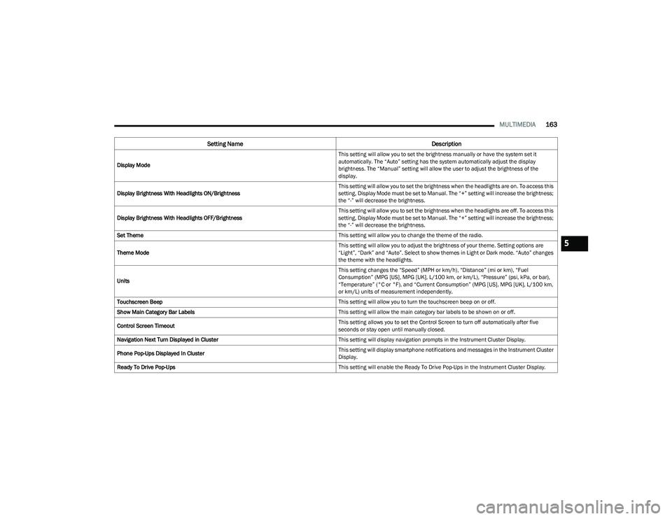
Display Mode This setting will allow you to set the brightness manually or have the system set it
automatically. The “Auto” setting has the system automatically adjust the display
brightness. The “Manual” setting will allow the user to adjust the brightness of the
display.
Display Brightness With Headlights ON/Brightness This setting will allow you to set the brightness when the headlights are on. To access this
setting, Display Mode must be set to Manual. The “+” setting will increase the brightness;
the “-” will decrease the brightness.
Display Brightness With Headlights OFF/Brightness This setting will allow you to set the brightness when the headlights are off. To access this
setting, Display Mode must be set to Manual. The “+” setting will increase the brightness;
the “-” will decrease the brightness.
Set Theme This setting will allow you to change the theme of the radio.
Theme Mode This setting will allow you to adjust the brightness of your theme. Setting options are
“Light”, “Dark” and “Auto”. Select to show themes in Light or Dark mode. “Auto” changes
the theme with the headlights.
Units This setting changes the “Speed” (MPH or km/h), “Distance” (mi or km), “Fuel
Consumption” (MPG [US], MPG [UK], L/100 km, or km/L), “Pressure” (psi, kPa, or bar),
“Temperature” (°C or °F), and “Current Consumption” (MPG [US], MPG [UK], L/100 km,
or km/L) units of measurement independently.
Touchscreen Beep This setting will allow you to turn the touchscreen beep on or off.
Show Main Category Bar Labels This setting will allow the main category bar labels to be shown on or off.
Control Screen Timeout This setting allows you to set the Control Screen to turn off automatically after five
seconds or stay open until manually closed.
Navigation Next Turn Displayed in Cluster This setting will display navigation prompts in the Instrument Cluster Display.
Phone Pop-Ups Displayed In Cluster This setting will display smartphone notifications and messages in the Instrument Cluster
Display.
Ready To Drive Pop-Ups This setting will enable the Ready To Drive Pop-Ups in the Instrument Cluster Display.
Setting NameDescription
5
23_RUP_OM_EN_USC_t.book Page 163
Page 200 of 328

198SAFETY
The TPMS will warn the driver of a low tire pressure if the
tire pressure falls below the low-pressure warning limit for
any reason, including low temperature effects and natural
pressure loss through the tire.
The TPMS will continue to warn the driver of low tire
pressure as long as the condition exists, and will not turn
off until the tire pressure is at or above the recommended
cold placard pressure. Once the low tire pressure warning
(TPMS Warning Light) illuminates, you must increase the
tire pressure to the recommended cold placard pressure
in order for the TPMS Warning Light to turn off.
The system will automatically update and the TPMS
Warning Light will turn off once the system receives the
updated tire pressures. The vehicle may need to be driven
for up to 20 minutes above 15 mph (24 km/h) in order for
the TPMS to receive this information.
For example, your vehicle may have a recommended cold
(parked for more than three hours) placard pressure of
33 psi (227 kPa). If the ambient temperature is 68°F
(20°C) and the measured tire pressure is 28 psi
(193 kPa), a temperature drop to 20°F (-7°C) will
decrease the tire pressure to approximately 24 psi
(165 kPa). This tire pressure is low enough to turn on the
TPMS Warning Light. Driving the vehicle may cause the tire
pressure to rise to approximately 28 psi (193 kPa), but the
TPMS Warning Light will still be on. In this situation, the
TPMS Warning Light will turn off only after the tires are
inflated to the vehicle’s recommended cold placard
pressure value
Úpage 312.
NOTE:When filling warm tires, the tire pressure may need to be
increased up to an additional 4 psi (28 kPa) above the
recommended cold placard pressure in order to turn the
TPMS Warning Light off.NOTE:
The TPMS is not intended to replace normal tire care
and maintenance, or to provide warning of a tire failure
or condition.
The TPMS should not be used as a tire pressure gauge
while adjusting your tire pressure.
Driving on a significantly underinflated tire causes the
tire to overheat and can lead to tire failure. Underinfla -
tion also reduces fuel efficiency and tire tread life, and
may affect the vehicle’s handling and stopping ability.
The TPMS is not a substitute for proper tire mainte -
nance, and it is the driver’s responsibility to maintain
correct tire pressure using an accurate tire pressure
gauge, even if underinflation has not reached the level
to trigger illumination of the TPMS Warning Light.
Seasonal temperature changes will affect tire pres -
sure, and the TPMS will monitor the actual tire pres -
sure in the tire.
Premium System
The Tire Pressure Monitoring System (TPMS) uses wireless
technology with wheel rim mounted electronic sensors to
monitor tire pressure levels. Sensors, mounted to each
wheel as part of the valve stem, transmit tire pressure
readings to the receiver module.
NOTE:It is particularly important for you to check the tire
pressure in all of the tires on your vehicle monthly and to
maintain the proper pressure.
CAUTION!
The TPMS has been optimized for the original equip -
ment tires and wheels. TPMS pressures and warning
have been established for the tire size equipped on
your vehicle. Undesirable system operation or sensor
damage may result when using replacement equip -
ment that is not of the same size, type, and/or style.
The TPMS sensor is not designed for use on after -
market wheels and may contribute to a poor overall
system performance or sensor damage. Customers
are encouraged to use Original Equipment Manufac -
turer (OEM) wheels to ensure proper TPMS feature
operation.
Using aftermarket tire sealants may cause the Tire
Pressure Monitoring System (TPMS) sensor to
become inoperable. After using an aftermarket tire
sealant it is recommended that you take your vehicle
to an authorized dealer to have your sensor function
checked.
After inspecting or adjusting the tire pressure always
reinstall the valve stem cap. This will prevent mois -
ture and dirt from entering the valve stem, which
could damage the TPMS sensor.
23_RUP_OM_EN_USC_t.book Page 198
Page 220 of 328
218SAFETY
(Continued)
Enhanced Accident Response System
In the event of an impact, if the communication network
remains intact, and the power remains intact, depending
on the nature of the event, the Occupant Restraint
Controller (ORC) will determine whether to have the
Enhanced Accident Response System perform the
following functions:
Cut off fuel to the engine (if equipped).
Cut off battery power to the electric motor (if equipped).
Flash hazard lights as long as the battery has power.
Turn on the interior lights, which remain on as long as
the battery has power or for 15 minutes from the inter -
vention of the Enhanced Accident Response System.
Unlock the power door locks.
Your vehicle may also be designed to perform any of these
other functions in response to the Enhanced Accident
Response System:
Turn off the Fuel Filter Heater, Turn off the HVAC Blower
Motor, Close the HVAC Circulation Door
Cut off battery power to the:
Engine
Electric Motor (if equipped)
Electric power steering
Brake booster
Electric park brake
Automatic transmission gear selector
Horn
Front wiper
Headlight washer pump (if equipped)
NOTE:After an accident, remember to cycle the ignition to the
STOP (OFF/LOCK) position and remove the key from the
ignition switch to avoid draining the battery. Carefully
check the vehicle for fuel leaks in the engine compartment
and on the ground near the engine compartment and fuel
tank before resetting the system and starting the engine.
If there are no fuel leaks or damage to the vehicle elec -
trical devices (e.g. headlights) after an accident, reset the
system by following the procedure described below. If you
have any doubt, contact an authorized dealer.
Enhanced Accident Response System
Reset Procedure
If applicable, refer to the “Hybrid Supplement” for
additional information.
In order to reset the Enhanced Accident Response System
functions after an event, the ignition switch must be
changed from ignition START or ON/RUN to ignition OFF.
Carefully check the vehicle for fuel leaks in the engine
compartment and on the ground near the engine
compartment and fuel tank before resetting the system
and starting the engine.
After an accident, if the vehicle will not start after
performing the reset procedure, the vehicle must be
towed to an authorized dealer to be inspected and to have
the Enhanced Accident Response System reset.
Maintaining Your Air Bag System
WARNING!
Modifications to any part of the air bag system could
cause it to fail when you need it. You could be injured
if the air bag system is not there to protect you. Do
not modify the components or wiring, including
adding any kind of badges or stickers to the steering
wheel hub trim cover or the upper passenger side of
the instrument panel. Do not modify the front fascia/
bumper, vehicle body structure, or add aftermarket
side steps or running boards.
23_RUP_OM_EN_USC_t.book Page 218
Page 237 of 328
SAFETY235
(Continued)
Lights
Have someone observe the operation of brake lights and
exterior lights while you work the controls. Check turn
signal and high beam indicator lights on the instrument
panel.
Door Latches
Check for proper closing, latching, and locking.
Fluid Leaks
Check area under the vehicle after overnight parking for
fuel, coolant, oil, or other fluid leaks. Also, if gasoline
fumes are detected or if fuel or brake fluid leaks are
suspected, the cause should be located and corrected
immediately.
EXHAUST GAS
The best protection against carbon monoxide entry into
the vehicle body is a properly maintained engine exhaust
system.
Whenever a change is noticed in the sound of the exhaust
system, when exhaust fumes can be detected inside the
vehicle, or when the underside or rear of the vehicle is
damaged, have an authorized dealer inspect the complete
exhaust system and adjacent body areas for broken,
damaged, deteriorated, or mispositioned parts. Open
seams or loose connections could permit exhaust fumes
to seep into the passenger compartment. In addition,
inspect the exhaust system each time the vehicle is raised
for lubrication or oil change. Replace as required.
CARBON MONOXIDE WARNINGS
WARNING!
Exhaust gases can injure or kill. They contain carbon
monoxide (CO), which is colorless and odorless.
Breathing it can make you unconscious and can
eventually poison you. To avoid breathing (CO), follow
these safety tips:
Do not run the engine in a closed garage or in
confined areas any longer than needed to move your
vehicle in or out of the area.
If you are required to drive with the trunk/liftgate/
rear doors open, make sure that all windows are
closed and the climate control BLOWER switch is set
at high speed. DO NOT use the recirculation mode.
If it is necessary to sit in a parked vehicle with the
engine running, adjust your heating or cooling
controls to force outside air into the vehicle. Set the
blower at high speed.
WARNING!
WARNING!
Carbon monoxide (CO) in exhaust gases is deadly.
Follow the precautions below to prevent carbon
monoxide poisoning:
Do not inhale exhaust gases. They contain carbon
monoxide, a colorless and odorless gas, which can
kill. Never run the engine in a closed area, such as a
garage, and never sit in a parked vehicle with the
engine running for an extended period. If the vehicle
is stopped in an open area with the engine running
for more than a short period, adjust the ventilation
system to force fresh, outside air into the vehicle.
Guard against carbon monoxide with proper mainte -
nance. Have the exhaust system inspected every
time the vehicle is raised. Have any abnormal condi -
tions repaired promptly. Until repaired, drive with all
side windows fully open.
When exiting the vehicle, always make sure the igni -
tion is in the OFF position, remove the key fob from
the vehicle, and lock your vehicle.
6
23_RUP_OM_EN_USC_t.book Page 235
Page 242 of 328
240IN CASE OF EMERGENCY
(Continued)
JACK AND SPARE TIRE LOCATION
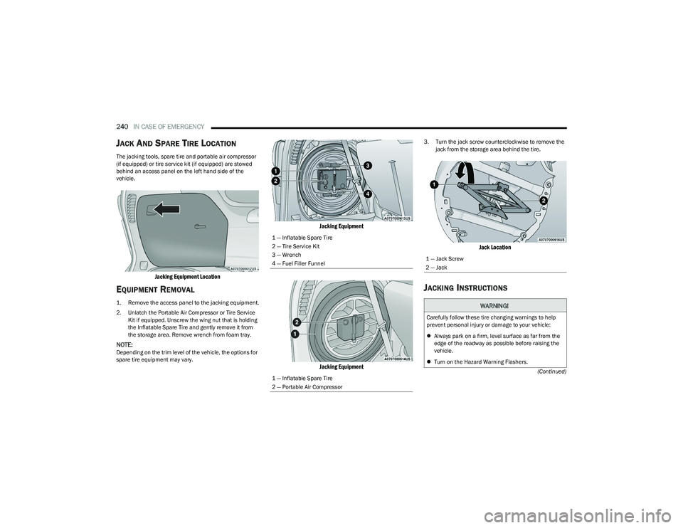
The jacking tools, spare tire and portable air compressor
(if equipped) or tire service kit (if equipped) are stowed
behind an access panel on the left hand side of the
vehicle.
Jacking Equipment Location
EQUIPMENT REMOVAL
1. Remove the access panel to the jacking equipment.
2. Unlatch the Portable Air Compressor or Tire Service
Kit if equipped. Unscrew the wing nut that is holding
the Inflatable Spare Tire and gently remove it from
the storage area. Remove wrench from foam tray.
NOTE:Depending on the trim level of the vehicle, the options for
spare tire equipment may vary.
Jacking Equipment
Jacking Equipment
3. Turn the jack screw counterclockwise to remove the jack from the storage area behind the tire.
Jack Location
JACKING INSTRUCTIONS
1 — Inflatable Spare Tire
2 — Tire Service Kit
3 — Wrench
4 — Fuel Filler Funnel
1 — Inflatable Spare Tire
2 — Portable Air Compressor
1 — Jack Screw
2 — Jack
WARNING!
Carefully follow these tire changing warnings to help
prevent personal injury or damage to your vehicle:
Always park on a firm, level surface as far from the
edge of the roadway as possible before raising the
vehicle.
Turn on the Hazard Warning Flashers.
23_RUP_OM_EN_USC_t.book Page 240
Page 254 of 328
252IN CASE OF EMERGENCY
JUMP STARTING PROCEDURE
Connecting The Jumper Cables
1. Connect the positive
(+) end of the jumper cable to
the positive (+)
post of the vehicle with the
discharged battery.
2. Connect the opposite end of the positive (+) jumper
cable to the positive (+) post of the booster battery.
3. Connect the negative (-) end of the jumper cable to
the negative (-) post of the booster battery.
4. Connect the opposite end of the negative (-) jumper
cable to the remote negative (-) post near the
windshield cowl (exposed metallic/unpainted post of
the discharge vehicle). 5. Start the engine in the vehicle that has the booster
battery, let the engine idle a few minutes, and then
start the engine in the vehicle with the discharged
battery.
6. Once the engine is started, see the following discon- necting procedure for the next steps.
Disconnecting The Jumper Cables
1. Disconnect the negative
(-)
end of the jumper cable
from the remote negative post of the vehicle with the
discharged battery.
2. Disconnect the opposite end of the negative (-)
jumper cable from the negative (-) post of the booster
battery.
3. Disconnect the positive (+) end of the jumper cable
from the positive (+) post of the booster battery.
4. Disconnect the opposite end of the positive (+)
jumper cable from the positive (+) post of the vehicle
with the discharged battery and reinstall the
protective cap.
If frequent jump starting is required to start your vehicle
you should have the battery and charging system
inspected at an authorized dealer.
REFUELING IN EMERGENCY – IF EQUIPPED
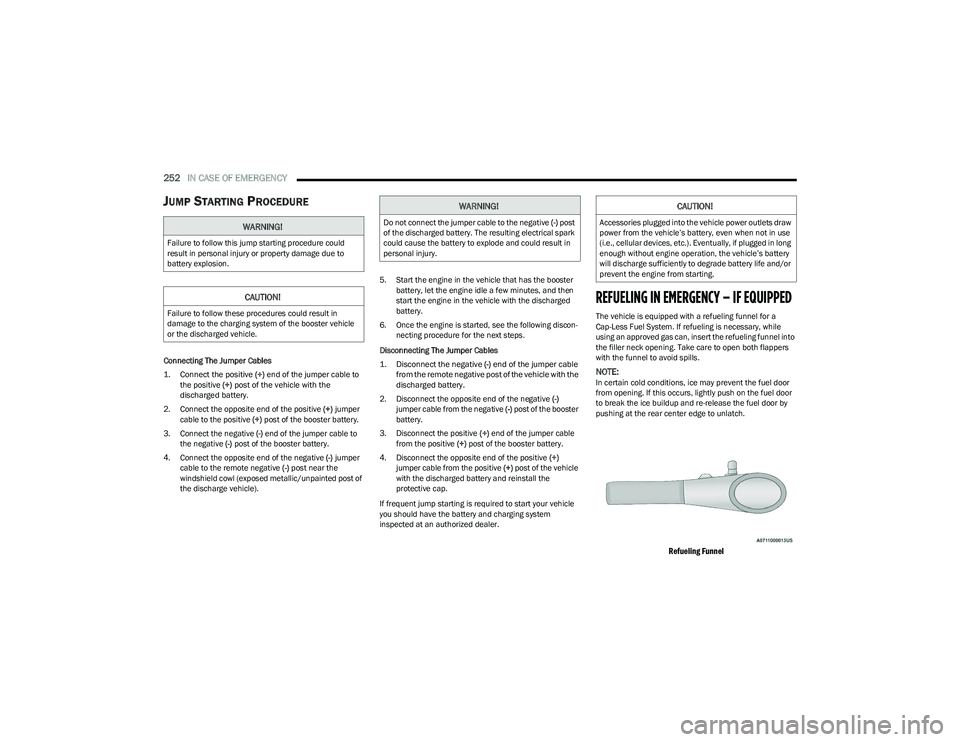
The vehicle is equipped with a refueling funnel for a
Cap-Less Fuel System. If refueling is necessary, while
using an approved gas can, insert the refueling funnel into
the filler neck opening. Take care to open both flappers
with the funnel to avoid spills.
NOTE:In certain cold conditions, ice may prevent the fuel door
from opening. If this occurs, lightly push on the fuel door
to break the ice buildup and re-release the fuel door by
pushing at the rear center edge to unlatch.
Refueling Funnel
WARNING!
Failure to follow this jump starting procedure could
result in personal injury or property damage due to
battery explosion.
CAUTION!
Failure to follow these procedures could result in
damage to the charging system of the booster vehicle
or the discharged vehicle.
WARNING!
Do not connect the jumper cable to the negative (-) post
of the discharged battery. The resulting electrical spark
could cause the battery to explode and could result in
personal injury.
CAUTION!
Accessories plugged into the vehicle power outlets draw
power from the vehicle’s battery, even when not in use
(i.e., cellular devices, etc.). Eventually, if plugged in long
enough without engine operation, the vehicle’s battery
will discharge sufficiently to degrade battery life and/or
prevent the engine from starting.
23_RUP_OM_EN_USC_t.book Page 252
Page 255 of 328
IN CASE OF EMERGENCY253
(Continued)
Emergency Gas Can Refueling
Most gas cans will not open the flapper doors. A funnel is
provided to allow emergency refueling with a gas can.
See the following steps for refueling:
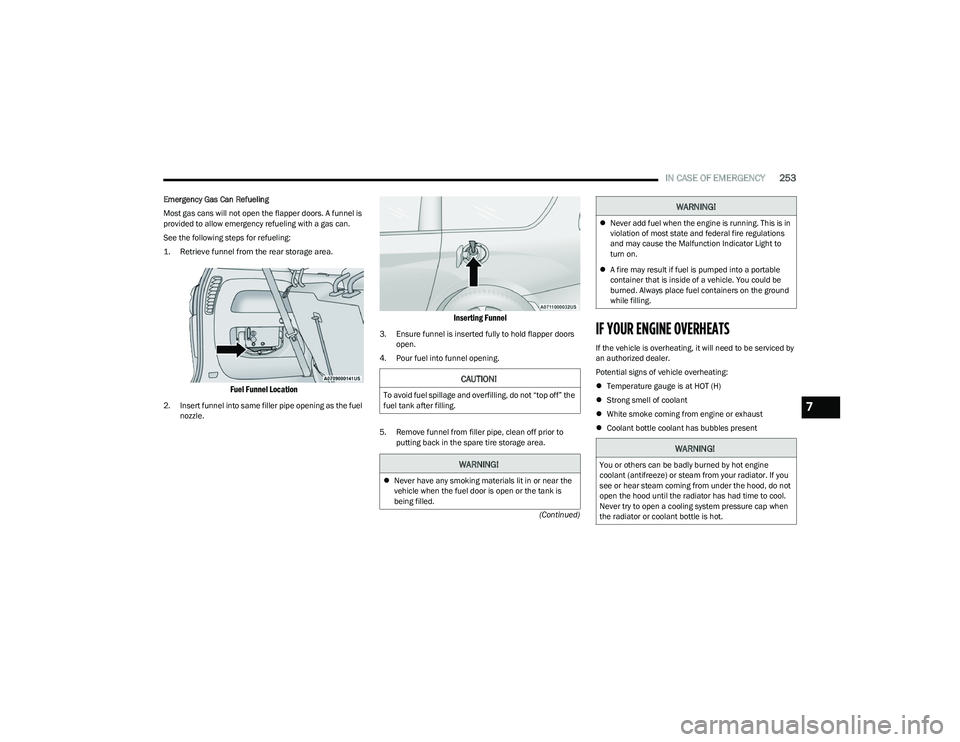
1. Retrieve funnel from the rear storage area.
Fuel Funnel Location
2. Insert funnel into same filler pipe opening as the fuel
nozzle.
Inserting Funnel
3. Ensure funnel is inserted fully to hold flapper doors open.
4. Pour fuel into funnel opening.
5. Remove funnel from filler pipe, clean off prior to putting back in the spare tire storage area.IF YOUR ENGINE OVERHEATS
If the vehicle is overheating, it will need to be serviced by
an authorized dealer.
Potential signs of vehicle overheating:
Temperature gauge is at HOT (H)
Strong smell of coolant
White smoke coming from engine or exhaust
Coolant bottle coolant has bubbles present
CAUTION!
To avoid fuel spillage and overfilling, do not “top off” the
fuel tank after filling.
WARNING!
Never have any smoking materials lit in or near the
vehicle when the fuel door is open or the tank is
being filled.
Never add fuel when the engine is running. This is in
violation of most state and federal fire regulations
and may cause the Malfunction Indicator Light to
turn on.
A fire may result if fuel is pumped into a portable
container that is inside of a vehicle. You could be
burned. Always place fuel containers on the ground
while filling.
WARNING!
You or others can be badly burned by hot engine
coolant (antifreeze) or steam from your radiator. If you
see or hear steam coming from under the hood, do not
open the hood until the radiator has had time to cool.
Never try to open a cooling system pressure cap when
the radiator or coolant bottle is hot.
WARNING!
7
23_RUP_OM_EN_USC_t.book Page 253
Page 265 of 328
SERVICING AND MAINTENANCE263
CHECKING OIL LEVEL
To ensure proper engine lubrication, the engine oil must
be maintained at the correct level. Check the oil level at
regular intervals, such as every fuel stop. The best time to
check the engine oil level is about five minutes after a fully
warmed up engine is shut off.
Checking the oil while the vehicle is on level ground will
improve the accuracy of the oil level readings.
There are four possible dipstick types:
Crosshatched zone.
Crosshatched zone marked SAFE.
Crosshatched zone marked with MIN at the low end of
the range and MAX at the high end of the range.
Crosshatched zone marked with dimples at the MIN
and the MAX ends of the range.
NOTE:Always maintain the oil level within the crosshatch
markings on the dipstick.
Adding 1 qt (1 L) of oil when the reading is at the low end
of the dipstick range will raise the oil level to the high end
of the range marking.
ADDING WASHER FLUID
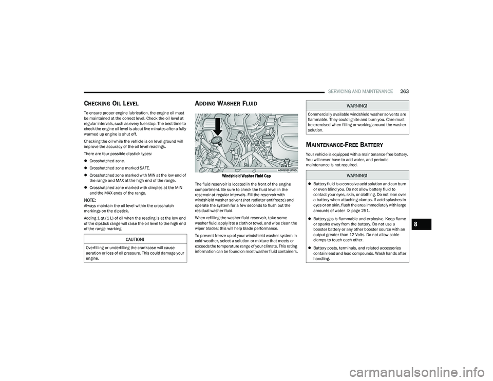
Windshield Washer Fluid Cap
The fluid reservoir is located in the front of the engine
compartment. Be sure to check the fluid level in the
reservoir at regular intervals. Fill the reservoir with
windshield washer solvent (not radiator antifreeze) and
operate the system for a few seconds to flush out the
residual washer fluid.
When refilling the washer fluid reservoir, take some
washer fluid, apply it to a cloth or towel, and wipe clean the
wiper blades; this will help blade performance.
To prevent freeze-up of your windshield washer system in
cold weather, select a solution or mixture that meets or
exceeds the temperature range of your climate. This rating
information can be found on most washer fluid containers.
MAINTENANCE-FREE BATTERY
Your vehicle is equipped with a maintenance-free battery.
You will never have to add water, and periodic
maintenance is not required.
CAUTION!
Overfilling or underfilling the crankcase will cause
aeration or loss of oil pressure. This could damage your
engine.
WARNING!
Commercially available windshield washer solvents are
flammable. They could ignite and burn you. Care must
be exercised when filling or working around the washer
solution.
WARNING!
Battery fluid is a corrosive acid solution and can burn
or even blind you. Do not allow battery fluid to
contact your eyes, skin, or clothing. Do not lean over
a battery when attaching clamps. If acid splashes in
eyes or on skin, flush the area immediately with large
amounts of water
Úpage 251.
Battery gas is flammable and explosive. Keep flame
or sparks away from the battery. Do not use a
booster battery or any other booster source with an
output greater than 12 Volts. Do not allow cable
clamps to touch each other.
Battery posts, terminals, and related accessories
contain lead and lead compounds. Wash hands after
handling.
8
23_RUP_OM_EN_USC_t.book Page 263