2023 CHRYSLER PACIFICA HYBRID ESP
[x] Cancel search: ESPPage 53 of 328
GETTING TO KNOW YOUR VEHICLE51
TILT SIDE MIRRORS IN REVERSE —
I
F EQUIPPED
Tilt Side Mirrors In Reverse provides automatic outside
mirror positioning which will aid the driver’s view of the
ground rearward of the front doors. The driver's outside
mirror will move slightly downward from the present
position when the vehicle is shifted into REVERSE. The
driver's outside mirror will then return to the original
position when the vehicle is shifted out of the REVERSE
position. Each stored memory setting will have an
associated Tilt Side Mirrors In Reverse position.
NOTE:The Tilt Side Mirrors In Reverse feature can be enabled or
disabled through the Uconnect system Úpage 157.
UNIVERSAL GARAGE DOOR OPENER
(HOMELINK®) — IF EQUIPPED
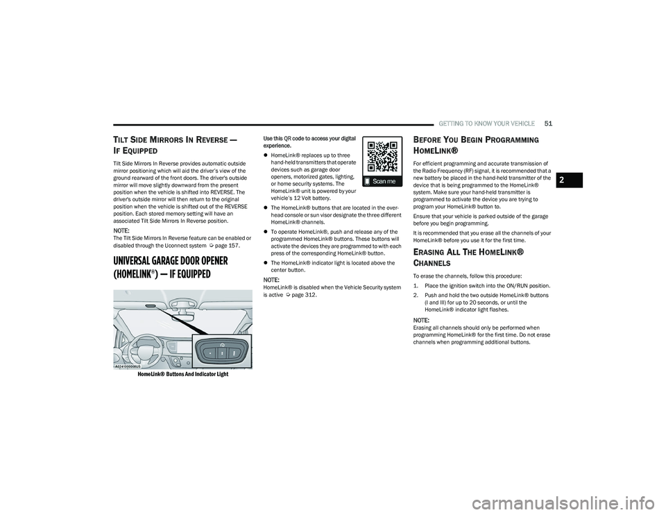
HomeLink® Buttons And Indicator Light
Use this QR code to access your digital
experience.
HomeLink® replaces up to three
hand-held transmitters that operate
devices such as garage door
openers, motorized gates, lighting,
or home security systems. The
HomeLink® unit is powered by your
vehicle’s 12 Volt battery.
The HomeLink® buttons that are located in the over -
head console or sun visor designate the three different
HomeLink® channels.
To operate HomeLink®, push and release any of the
programmed HomeLink® buttons. These buttons will
activate the devices they are programmed to with each
press of the corresponding HomeLink® button.
The HomeLink® indicator light is located above the
center button.
NOTE:HomeLink® is disabled when the Vehicle Security system
is active Úpage 312.
BEFORE YOU BEGIN PROGRAMMING
H
OMELINK®
For efficient programming and accurate transmission of
the Radio Frequency (RF) signal, it is recommended that a
new battery be placed in the hand-held transmitter of the
device that is being programmed to the HomeLink®
system. Make sure your hand-held transmitter is
programmed to activate the device you are trying to
program your HomeLink® button to.
Ensure that your vehicle is parked outside of the garage
before you begin programming.
It is recommended that you erase all the channels of your
HomeLink® before you use it for the first time.
ERASING ALL THE HOMELINK®
C
HANNELS
To erase the channels, follow this procedure:
1. Place the ignition switch into the ON/RUN position.
2. Push and hold the two outside HomeLink® buttons
(I and III) for up to 20 seconds, or until the
HomeLink® indicator light flashes.
NOTE:Erasing all channels should only be performed when
programming HomeLink® for the first time. Do not erase
channels when programming additional buttons.
2
23_RUP_OM_EN_USC_t.book Page 51
Page 87 of 328

GETTING TO KNOW YOUR VEHICLE85
Vehicles Equipped With A Trailer Tow Package
NOTE:If your vehicle is equipped with the Trailer Tow Package,
the hands-free activation zone(s) for the Power Liftgate
will be located on the left and right side of the receiver.
Use a straight kicking motion under either activation zone
to open the Hands-Free Liftgate.
Hands-Free Liftgate Trailer Tow Activation Zones
When a valid kicking motion is completed, the liftgate will
chime, the hazard lights will flash and the liftgate will open
after approximately one second. This assumes all options
are enabled in the Uconnect system.
NOTE:To open the Hands-Free Liftgate requires a valid Passive
Entry key fob within 5 ft (1.5 m) of the door handle. If a
valid Passive Entry key fob is not within 5 ft (1.5 m), the
liftgate will not respond to any kicks.
NOTE:
The Hands-Free Liftgate will only operate when the
transmission is in PARK.
If anything obstructs the Hands-Free Liftgate while it is
opening or closing, the liftgate will automatically
reverse to the closed position, provided it meets suffi -
cient resistance.
There are pinch sensors attached to the side of the lift -
gate opening. Light pressure anywhere along these
strips will cause the liftgate to return to the open posi -
tion.
If the power liftgate encounters multiple obstructions
within the same cycle, the system will automatically stop.
If this occurs, the liftgate must be operated manually.
The power liftgate will release, but not power open, in
temperatures below −12°F (−24°C). Be sure to
remove any buildup of snow or ice from the liftgate
before opening the liftgate.
If the liftgate is left open for an extended period of time,
the liftgate may need to be closed manually to reset
power liftgate functionality.
The Hands-Free Liftgate only works to open the liftgate. Gas props support the liftgate in the open position.
However, because the gas pressure drops with
temperature, it may be necessary to assist the props when
opening the liftgate in cold weather.
NOTE:Allow the power system to open the liftgate. Manually
pushing or pulling the liftgate may activate the liftgate
obstacle detection feature and stop the power operation
or reverse its direction.
CAUTION!
The Hands-Free Liftgate feature may be turned on or off
in Uconnect Settings. The Hands-Free Liftgate feature
should be turned off during jacking, tire changing, and
vehicle service
Úpage 157.
WARNING!
Driving with the liftgate open can allow poisonous
exhaust gases into your vehicle. You and your
passengers could be injured by these fumes. Keep
the liftgate closed when you are operating the
vehicle.
If you are required to drive with the liftgate open,
make sure that all windows are closed, and the
climate control blower switch is set at high speed. Do
not use the recirculation mode.
WARNING!
During power operation, personal injury or cargo
damage may occur. Ensure the liftgate travel path is
clear. Make sure the liftgate is closed and latched
before driving away.
2
23_RUP_OM_EN_USC_t.book Page 85
Page 95 of 328
GETTING TO KNOW YOUR VEHICLE93
(Continued)
NOTE:
To help control wind noise, stow the crossbars in the
side rails when they are not in use.
If any metallic object is placed over the satellite radio
antenna (if equipped), you may experience interruption
of satellite radio reception.
WARNING!
Cargo must be securely tied down before driving your
vehicle. Anything improperly secured to the roof rack,
crossbars, or the roof itself can fly off the vehicle,
particularly at high speeds, resulting in collisions,
personal injury, or property damage. Follow the roof
rack cautions when carrying anything on your roof rack.
CAUTION!
To prevent damage to the roof of your vehicle, DO
NOT carry any loads on the roof rack without the
crossbars deployed. The load should be secured and
placed on top of the crossbars, not directly on the
roof. If it is necessary to place the load on the roof,
place a blanket or other protective layer between the
load and the roof surface.
To avoid damage to the roof rack and vehicle, do not
exceed the maximum roof rack load capacity of 150
lb (68 kg). Always distribute heavy loads as evenly as
possible and appropriately secure the load and any
protective layer placed between the load and the roof
surface.Load should always be secured to cross bars first,
with tie down loops used as additional securing
points if needed. Tie loops are intended as supple -
mentary tie down points only. Do not use ratcheting
mechanisms with the tie loops. Check the straps and
thumb wheels frequently to be sure that the load
remains securely attached.
Long loads that extend over the windshield, such as
wood panels or surfboards, or loads with large frontal
area should be secured to both the front and rear of
the vehicle.
Travel at reduced speeds and turn corners carefully
when carrying large or heavy loads on the roof rack.
Wind forces, due to natural causes or nearby truck
traffic, can add sudden upward lift to a load. This is
especially true on large flat loads and may result in
damage to the cargo or your vehicle.
CAUTION!
2
23_RUP_OM_EN_USC_t.book Page 93
Page 102 of 328
100GETTING TO KNOW YOUR INSTRUMENT PANEL
Oil Life
Displays the remaining engine oil life as a percentage.
To reset the Oil Life, you must hold the OK button. The
“Hold OK to Reset” instruction will be displayed at all
times, but the following conditions will need to be met in
order to reset Oil Life:
The ignition must be in the ON/RUN position.
If the conditions are met, holding the OK button will reset
the gauge and the numeric display will return to 100%.
If the conditions are not met, a pop-up message will
display for five seconds, describing the required
conditions, and then the Oil Life screen will reappear.
Battery Voltage
Displays the actual battery voltage.
Engine Hours — If Equipped
Displays the number of hours of engine operation.
Driver Assist — If Equipped
Push and release the up or down arrow button until
the Driver Assist display icon is highlighted in the
instrument cluster display.
Adaptive Cruise Control
LaneSense
Fuel Economy
Push and release the up or down arrow button until
the Fuel Economy Menu item is highlighted in the
instrument cluster display. The Fuel Economy Menu will
display the following:
Two submenu pages that can be toggled between
using the left and right arrow buttons; one with
Current Value displayed and one without the Current
Value displayed:
Average Fuel Economy (MPG, L/100 km, or km/L)
Range To Empty (miles or km)
Current Fuel Economy (MPG, L/100 km, or km/L)
The Max and Min values will correspond to the
particular engine requirements
Hold OK to reset average fuel economy information.
Trip Info
Push and release the up or down arrow button until
the Trip Menu item is highlighted in the instrument cluster
display. Push the left or right arrow button to scroll
through the Trip A and Trip B submenus. The Trip
information will display the following:
Distance
Average Fuel Economy
Elapsed Time
Hold the OK button to reset feature information.
Stop / Start – If Equipped
Push and release the up or down arrow button until
the Stop/Start menu title is displayed in the instrument
cluster display.
Audio
Push and release the up or down arrow button until
the Audio Menu displays in the instrument cluster display.
Messages
Push and release the up or down arrow button until
Messages is highlighted in the instrument cluster display.
This feature shows the number of stored warning
messages. Pushing the right arrow button will allow you
to see what the stored messages are.
NOTE:The pop-up messages indicate the status of the system
and/or the conditions that need to be met. Messages
remain in the stored stack until condition is cleared.
Screen Setup
Push and release the up or down arrow button until
the Screen Setup Menu displays in the instrument cluster
display. Push and release the OK button to enter the
submenus. The Screen Setup feature allows you to
change what information is displayed in the instrument
cluster as well as the location that information is
displayed.
23_RUP_OM_EN_USC_t.book Page 100
Page 108 of 328
106GETTING TO KNOW YOUR INSTRUMENT PANEL
Low Washer Fluid Warning Light —
If Equipped
This warning light will illuminate and a single
chime will sound when the windshield washer
fluid is low.
Engine Check/Malfunction Indicator
Warning Light
The Engine Check/Malfunction Indicator Light
(MIL) is a part of an Onboard Diagnostic System
called OBD II that monitors engine and
automatic transmission control systems. This
warning light will illuminate when the ignition is in the ON/
RUN position before engine start. If the bulb does not
come on when turning the ignition switch from OFF to ON/
RUN, have the condition checked promptly.
Certain conditions, such as a loose or missing gas cap,
poor quality fuel, etc., may illuminate the light after engine
start. The vehicle should be serviced if the light stays on
through several typical driving styles. In most situations,
the vehicle will drive normally and will not require towing.
When the engine is running, the MIL may flash to alert
serious conditions that could lead to immediate loss of
power or severe catalytic converter damage. The vehicle
should be serviced by an authorized dealer as soon as
possible if this occurs.
Service AWD Warning Light — If Equipped
This telltale will turn on to indicate that the All
Wheel Drive (AWD) system is not functioning
properly and that service is required. Contact
an authorized dealer.
Service Forward Collision Warning (FCW)
or Pedestrian Emergency Braking (PEB)
Warning Light — If Equipped
This warning light will illuminate to indicate a
fault in the FCW or PEB Warning System.
Contact an authorized dealer for service
Úpage 195.
Service LaneSense Warning Light —
If Equipped
This warning light will illuminate when the
LaneSense system is not operating and
requires service. Please see an authorized
dealer.
Service Stop/Start System Warning Light —
If Equipped
This warning light will illuminate when the
Stop/Start system is not functioning properly
and service is required. Contact an authorized
dealer for service
Úpage 121.
Tire Pressure Monitoring System (TPMS)
Warning Light
The warning light switches on and a message is
displayed to indicate that the tire pressure is
lower than the recommended value and/or
that slow pressure loss is occurring. In these
cases, optimal tire duration and fuel consumption may not
be guaranteed.
Should one or more tires be in the condition previously
mentioned, the display will show the indications
corresponding to each tire.
WARNING!
A malfunctioning catalytic converter can reach higher
temperatures than in normal operating conditions. This
can cause a fire if you drive slowly or park over
flammable substances such as dry plants, wood,
cardboard, etc. This could result in death or serious
injury to the driver, occupants or others.
CAUTION!
Prolonged driving with the Malfunction Indicator Light
(MIL) on could cause damage to the vehicle control
system. It also could affect fuel economy and
driveability. If the MIL is flashing, severe catalytic
converter damage and power loss will soon occur.
Immediate service is required.
23_RUP_OM_EN_USC_t.book Page 106
Page 109 of 328

GETTING TO KNOW YOUR INSTRUMENT PANEL107
Each tire, including the spare (if provided), should be
checked monthly when cold and inflated to the inflation
pressure recommended by the vehicle manufacturer on
the vehicle placard or tire inflation pressure label. If your
vehicle has tires of a different size than the size indicated
on the vehicle placard or tire inflation pressure label, you
should determine the proper tire inflation pressure for
those tires.
As an added safety feature, your vehicle has been
equipped with a TPMS that illuminates a low tire pressure
telltale when one or more of your tires is significantly
underinflated. Accordingly, when the low tire pressure
telltale illuminates, you should stop and check your tires
as soon as possible, and inflate them to the proper
pressure. Driving on a significantly underinflated tire
causes the tire to overheat and can lead to tire failure.
Underinflation also reduces fuel efficiency and tire tread
life, and may affect the vehicle’s handling and stopping
ability.
Please note that the TPMS is not a substitute for proper
tire maintenance, and it is the driver’s responsibility to
maintain correct tire pressure, even if underinflation has
not reached the level to trigger illumination of the TPMS
low tire pressure telltale. Your vehicle has also been equipped with a TPMS
malfunction indicator to indicate when the system is not
operating properly. The TPMS malfunction indicator is
combined with the low tire pressure telltale. When the
system detects a malfunction, the telltale will flash for
approximately one minute and then remain continuously
illuminated. This sequence will continue upon subsequent
vehicle start-ups as long as the malfunction exists. When
the malfunction indicator is illuminated, the system may
not be able to detect or signal low tire pressure as
intended. TPMS malfunctions may occur for a variety of
reasons, including the installation of replacement or
alternate tires or wheels on the vehicle that prevent the
TPMS from functioning properly. Always check the TPMS
malfunction telltale after replacing one or more tires or
wheels on your vehicle to ensure that the replacement or
alternate tires and wheels allow the TPMS to continue to
function properly.
YELLOW INDICATOR LIGHTS
Forward Collision Warning (FCW) or
Pedestrian Emergency Braking (PEB) OFF
Indicator Light — If Equipped
This indicator light illuminates to indicate that
Forward Collision Warning (FCW) or Pedestrian
Emergency Braking (PEB) is off.
GREEN INDICATOR LIGHTS
Adaptive Cruise Control (ACC) Set With
Target Vehicle Detected Indicator Light —
If Equipped
This indicator light will illuminate when the
Adaptive Cruise Control speed is SET and the
vehicle in front is detected
Úpage 124.
Adaptive Cruise Control (ACC) Set With No
Target Detected Indicator Light —
If Equipped
This indicator light will illuminate when the
Adaptive Cruise Control speed is SET and there
is no vehicle in front detected
Úpage 124.
Cruise Control Set Indicator Light —
If Equipped
This indicator light will illuminate when the
cruise control is set to the desired speed
Úpage 123.
CAUTION!
Do not continue driving with one or more flat tires as
handling may be compromised. Stop the vehicle,
avoiding sharp braking and steering. If a tire puncture
occurs, repair immediately using the dedicated tire
repair kit and contact an authorized dealer as soon as
possible.
CAUTION!
The TPMS has been optimized for the original
equipment tires and wheels. TPMS pressures and
warning have been established for the tire size
equipped on your vehicle. Undesirable system
operation or sensor damage may result when using
replacement equipment that is not of the same size,
type, and/or style. Aftermarket wheels can cause
sensor damage. Using aftermarket tire sealants may
cause the Tire Pressure Monitoring System (TPMS)
sensor to become inoperable. After using an
aftermarket tire sealant it is recommended that you
take your vehicle to an authorized dealer to have your
sensor function checked.
3
23_RUP_OM_EN_USC_t.book Page 107
Page 110 of 328

108GETTING TO KNOW YOUR INSTRUMENT PANEL
Front Fog Indicator Light — If Equipped
This indicator light will illuminate when the
front fog lights are on.
KeySense Indicator Light — If Equipped
The KeySense indicator is illuminated when a
KeySense key is detected upon startup of the
vehicle. The indicator will remain lit for the
entire key cycle as a reminder that the
KeySense key is in use. While the KeySense key is in use,
the vehicle will respond to settings associated with the
KeySense profile
Úpage 12.
LaneSense Indicator Light — If Equipped
The LaneSense indicator light illuminates solid
green when both lane markings have been
detected and the system is “armed” and ready
to provide visual and torque warnings if an
unintentional lane departure occurs
Úpage 140.
Parking/Headlights On Indicator Light
This indicator light will illuminate when the
parking lights or headlights are turned on.
Stop/Start Active Indicator Light —
If Equipped
This indicator light will illuminate when the
Stop/Start function is in “Autostop” mode
Úpage 121.
Turn Signal Indicator Lights
When the left or right turn signal is activated,
the turn signal indicator will flash
independently and the corresponding exterior
turn signal lamps will flash. Turn signals can be
activated when the multifunction lever is moved down
(left) or up (right).
NOTE:
A continuous chime will sound if the vehicle is driven
more than 1 mile (1.6 km) with either turn signal on.
Check for an inoperative outside light bulb if either indi -
cator flashes at a rapid rate.
WHITE INDICATOR LIGHTS
Adaptive Cruise Control (ACC) Ready
Light — If Equipped
This indicator light will illuminate when the
vehicle equipped with ACC has been turned on
but not set
Úpage 124.
Cruise Control Ready Indicator Light
This indicator light will illuminate when the
cruise control is ready, but not set Úpage 123.
LaneSense Indicator Light — If Equipped
When the LaneSense system is ON, but not
armed, the LaneSense indicator light
illuminates solid white. This occurs when only
left, right, or neither lane line has been
detected. If a single lane line is detected, the system is
ready to provide only visual warnings if an unintentional
lane departure occurs on the detected lane line
Úpage 140.
23_RUP_OM_EN_USC_t.book Page 108
Page 121 of 328
STARTING AND OPERATING119
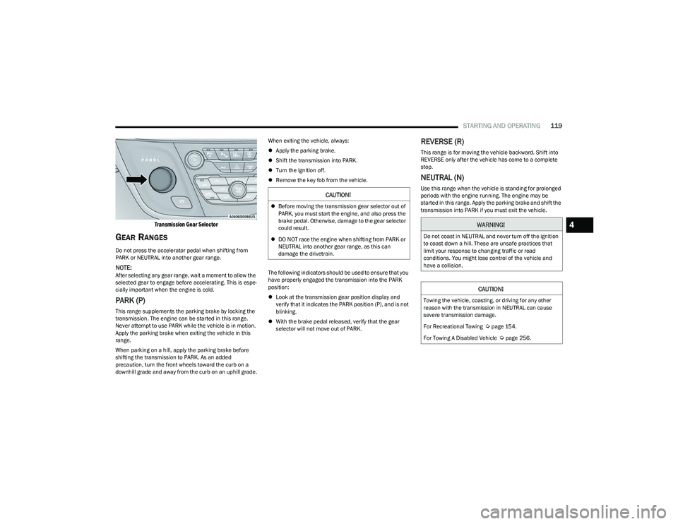
Transmission Gear Selector
GEAR RANGES
Do not press the accelerator pedal when shifting from
PARK or NEUTRAL into another gear range.
NOTE:After selecting any gear range, wait a moment to allow the
selected gear to engage before accelerating. This is espe -
cially important when the engine is cold.
PARK (P)
This range supplements the parking brake by locking the
transmission. The engine can be started in this range.
Never attempt to use PARK while the vehicle is in motion.
Apply the parking brake when exiting the vehicle in this
range.
When parking on a hill, apply the parking brake before
shifting the transmission to PARK. As an added
precaution, turn the front wheels toward the curb on a
downhill grade and away from the curb on an uphill grade. When exiting the vehicle, always:
Apply the parking brake.
Shift the transmission into PARK.
Turn the ignition off.
Remove the key fob from the vehicle.
The following indicators should be used to ensure that you
have properly engaged the transmission into the PARK
position:
Look at the transmission gear position display and
verify that it indicates the PARK position (P), and is not
blinking.
With the brake pedal released, verify that the gear
selector will not move out of PARK.
REVERSE (R)
This range is for moving the vehicle backward. Shift into
REVERSE only after the vehicle has come to a complete
stop.
NEUTRAL (N)
Use this range when the vehicle is standing for prolonged
periods with the engine running. The engine may be
started in this range. Apply the parking brake and shift the
transmission into PARK if you must exit the vehicle.CAUTION!
Before moving the transmission gear selector out of
PARK, you must start the engine, and also press the
brake pedal. Otherwise, damage to the gear selector
could result.
DO NOT race the engine when shifting from PARK or
NEUTRAL into another gear range, as this can
damage the drivetrain.
WARNING!
Do not coast in NEUTRAL and never turn off the ignition
to coast down a hill. These are unsafe practices that
limit your response to changing traffic or road
conditions. You might lose control of the vehicle and
have a collision.
CAUTION!
Towing the vehicle, coasting, or driving for any other
reason with the transmission in NEUTRAL can cause
severe transmission damage.
For Recreational Towing
Úpage 154.
For Towing A Disabled Vehicle
Úpage 256.
4
23_RUP_OM_EN_USC_t.book Page 119