2023 ALFA ROMEO STELVIO ECO mode
[x] Cancel search: ECO modePage 99 of 268

97
ALFA DNA SELECTOR
ALFA DNA SYSTEM
This vehicle is equipped with an Alfa DNA system
selector (located on the center console). There
are up to four modes of operation to be selected
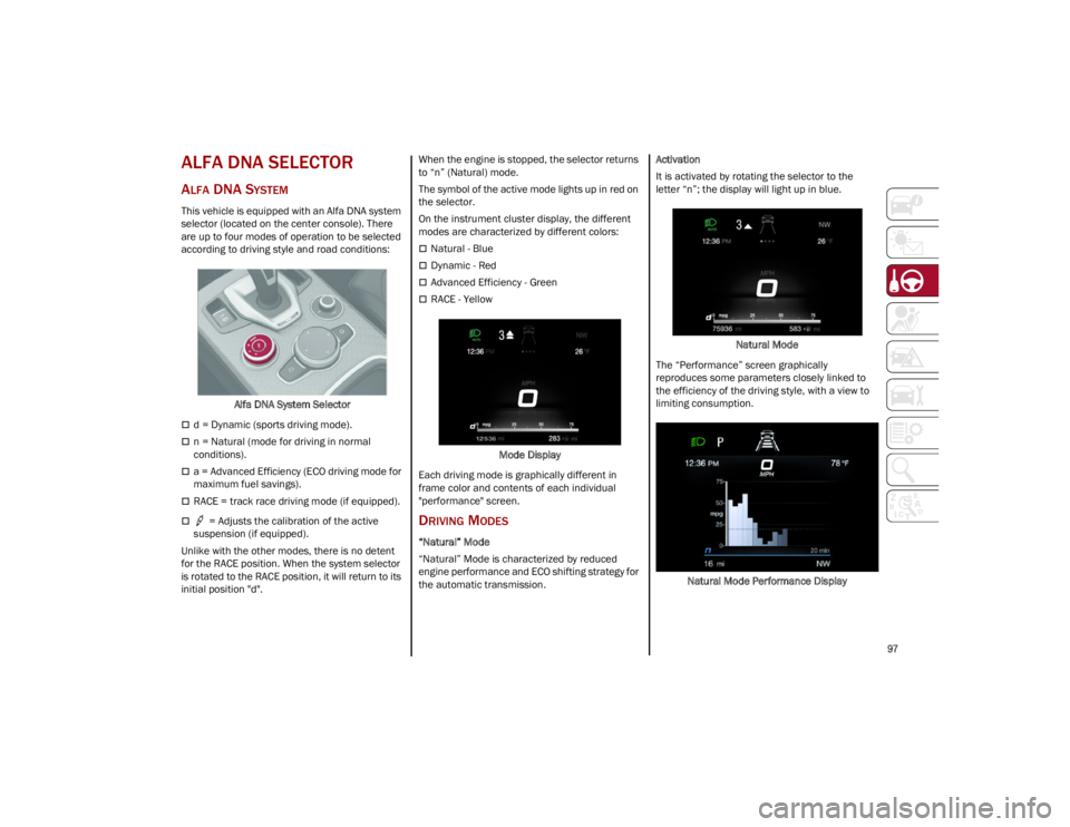
according to driving style and road conditions:Alfa DNA System Selector
d = Dynamic (sports driving mode).
n = Natural (mode for driving in normal
conditions).
a = Advanced Efficiency (ECO driving mode for
maximum fuel savings).
RACE = track race driving mode (if equipped).
= Adjusts the calibration of the active
suspension (if equipped).
Unlike with the other modes, there is no detent
for the RACE position. When the system selector
is rotated to the RACE position, it will return to its
initial position "d". When the engine is stopped, the selector returns
to “n” (Natural) mode.
The symbol of the active mode lights up in red on
the selector.
On the instrument cluster display, the different
modes are characterized by different colors:
Natural - Blue
Dynamic - Red
Advanced Efficiency - Green
RACE - Yellow
Mode Display
Each driving mode is graphically different in
frame color and contents of each individual
"performance" screen.
DRIVING MODES
“Natural” Mode
“Natural” Mode is characterized by reduced
engine performance and ECO shifting strategy for
the automatic transmission. Activation
It is activated by rotating the selector to the
letter “n”; the display will light up in blue.
Natural Mode
The “Performance” screen graphically
reproduces some parameters closely linked to
the efficiency of the driving style, with a view to
limiting consumption.
Natural Mode Performance Display
23_GU_OM_EN_USC_t.book Page 97
Page 106 of 268

STARTING AND OPERATING
104
To Vary The Speed Setting
To Increase Or Decrease The Set Speed
When the Cruise Control is set, you can increase
the speed by pushing the SET switch upward or
decrease the speed by pushing the SET switch
downward.
U.S. Speed (mph)
Pushing the SET switch once will result in a
1 mph speed adjustment. Each subsequent
movement of the switch results in an
adjustment of 1 mph.
If the switch is continually pushed, the set
speed will continue to adjust until the switch is
released, then the new set speed will be
established.
Metric Speed (km/h)
Pushing the SET switch once will result in a
1 km/h speed adjustment. Each subsequent
movement of the switch results in an
adjustment of 1 km/h.
If the switch is continually pushed, the set
speed will continue to adjust until the switch is
released, then the new set speed will be
established.
NOTE:
Moving the SET switch allows for adjusting of the
speed according to the selected unit of measure -
ment set on the radio system. Refer to the Infor -
mation and Entertainment System Owner’s
Manual for more information.
To Accelerate For Passing
While the Cruise Control is set, press the
accelerator to pass as you would normally. When
the pedal is released, the vehicle will return to the
set speed.
Using Cruise Control On Hills
The transmission may downshift on hills to
maintain the vehicle set speed.
The Cruise Control system maintains speed up
and down hills. A slight speed change on
moderate hills is normal. On steep hills, a greater
speed loss or gain may occur so it may be
preferable to drive without Cruise Control.
To Resume Speed
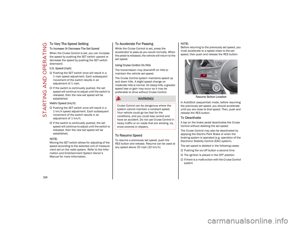
To resume a previously set speed, push the
RES button and release. Resume can be used at
any speed above 20 mph (32 km/h).
NOTE:
Before returning to the previously set speed, you
must accelerate to a speed close to the set
speed, then push and release the RES button.
Resume Button Location
In AutoStick (sequential) mode, before resuming
the previously set speed, you should accelerate
until you are close to that speed. Then, push and
release the RES button.
To Deactivate
A tap on the brake pedal deactivates the Cruise
Control without deleting the set speed.
The Cruise Control may also be deactivated by
applying the Electric Park Brake or when the
braking system is operated (e.g. operation of the
Electronic Stability Control (ESC) system).
The set speed is deleted in the following cases:
Pushing the on/off button a second time
The ignition is placed in the OFF position
If there is a malfunction with the Cruise Control
system
WARNING!
Cruise Control can be dangerous where the
system cannot maintain a constant speed.
Your vehicle could go too fast for the
conditions, and you could lose control and
have an accident. Do not use Cruise Control in
heavy traffic or on roads that are winding, icy,
snow-covered or slippery.
23_GU_OM_EN_USC_t.book Page 104
Page 111 of 268

109
Overtake Aid
When driving with ACC engaged and following a
vehicle at a speed greater than 45 mph
(70 km/h), the system will provide an additional
acceleration up to the ACC set speed to assist in
passing the vehicle. This additional acceleration
is triggered when the driver utilizes the left turn
signal and will only be active when passing on the
left hand side.
The system detects the direction of traffic
automatically when the vehicle passes from left
hand traffic to right hand traffic. In this case, the
overtaking assist function is only active when the
reference vehicle is overtaken on the right. The
additional acceleration is deactivated when the
driver uses the right direction indicator and
returns to the original lane.
Stop And Go Function
The Stop and Go operating strategy allows you to
maintain a safe distance from the vehicle ahead
until the vehicle has completely stopped.
In the event that the ACC system brings your
vehicle to a standstill while following the vehicle
in front, if the vehicle in front starts moving within
two seconds of your vehicle coming to a
standstill, your vehicle will resume motion without
the need for any driver action.If the vehicle in front does not start moving within
two seconds of your vehicle coming to a
standstill, the driver will have to push the RES/
SET switch upward to restart.
Deactivation
The system is deactivated and the set speed is
canceled if:
The on/off button is pushed (when the system
is on or paused)
The ignition is placed in the OFF position
RACE mode is activated (Quadrifoglio models)
The system is canceled (the set speed and
distance are stored):
When the system is paused
Ú
page 106
When the conditions shown in the “Activating
Adaptive Cruise Control (ACC)” section occur
Ú
page 106
Limited Operation Warning
If the dedicated message is shown on the display,
a condition limiting the Adaptive Cruise Control
operation may have occurred.
This could be due to an obstruction of the
vehicle’s sensor or camera. It could also be due to
a fault in the system. If an obstruction is detected,
clean the area of the windshield opposite the
interior rearview mirror, where the camera is located, as well as the area of the front fascia/
bumper where the sensor is located. Then check
that the message has disappeared.
When the conditions limiting the system
functions end, normal operation will resume.
Should the fault persist, contact an authorized
dealer.
Precautions While Driving With ACC
In certain driving situations, ACC may have
detection issues. In these cases, ACC may brake
late or unexpectedly. The driver needs to stay
alert and may need to intervene. The following
are examples of these types of situations:
Towing A Trailer
Towing a trailer is not recommended when using
ACC.
Offset Driving
ACC may not detect a vehicle in the same lane
that is offset from your direct line of travel, or a
vehicle merging in from a side lane. There may
not be sufficient distance to the vehicle ahead.
The offset vehicle may move in and out of the line
of travel, which can cause your vehicle to brake or
accelerate unexpectedly.
Turns And Bends
When driving on a curve with ACC engaged, the
system may increase or decrease the vehicle
speed for stability, with no vehicle ahead
detected. Once the vehicle is out of the curve, the
system will resume your original set speed. This is
a part of normal ACC system functionality.
NOTE:
On tight turns ACC performance may be limited.
The driver is fully responsible for holding a
safe distance from the vehicle ahead
respecting the highway code in force in the
respective country.
WARNING!
WARNING!
When the ACC system is resumed, the driver
must ensure that there are no pedestrians,
vehicles or objects in the path of the vehicle.
Failure to follow these warnings can result in a
collision and death or serious personal injury.
23_GU_OM_EN_USC_t.book Page 109
Page 123 of 268

121
PARKSENSE SENSORS
The ParkSense sensors located in the rear
fascia/bumper and (if equipped) in the front
fascia/bumper, monitor the area in front and
behind the vehicle that is within the sensors’ field
of view. These sensors detect the presence of any
obstacles and warn the driver through an
acoustic signal and visual indications, which will
be displayed on the instrument cluster display.Front Sensor Locations
Rear Sensor Locations
PARKSENSE DISPLAY
The driver can select the type of warning they
would like to be displayed through the radio
system. To access the function on the main
menu, select in the following order:
1. Driver Assistance
2. ParkSense
3. Mode
4. Sound and Display
Visual Indications
The system indicates the presence of an obstacle
by displaying a single red arc in the detected area,
in relation to the distance of the object and the
position of the vehicle.
If the obstacle is detected in the front or rear
central area, a single red arc will be displayed as
the obstacle approaches, first constant, then
flashing, in addition to an acoustic signal.
If the obstacle is detected in the front or rear left
and/or right area, a single red flashing arc will be
shown in the corresponding area on the display
and the system will emit an acoustic signal, either
at frequent intervals or constantly.
In general, the vehicle is closer to the obstacle
when a single red flashing arc is shown on the
display and the acoustic signal becomes
continuous. If several obstacles are detected simultaneously
in the front and rear area, the display will show all
of them, regardless of the area in which they were
detected.
It is not possible to exit from the display screen
while the vehicle is in REVERSE.
Acoustic Signal
In the presence of an obstacle at the front or
the rear of the vehicle, an acoustic signal with
variable frequency will sound:
The acoustic signal increases in frequency as
the distance between the vehicle and the
obstacle decreases.
The acoustic signal becomes continuous when
the distance between the vehicle and the
obstacle is less than 11 inches (30 cm), and
stops if the distance increases.
The acoustic signal is constant if the distance
between the vehicle and the obstacle is
unchanged.
NOTE:
If the sensors detect several front and rear obsta
-
cles, the closest obstacle is considered. An inter -
mittent signal will sound if the obstacles are at
the same distance (front and rear).
When the system emits an acoustic signal, the
volume of the radio system, if activated, is
automatically lowered.
An acoustic signal will not sound if the vehicle is
in PARK.
23_GU_OM_EN_USC_t.book Page 121
Page 128 of 268

STARTING AND OPERATING
126
TURNING LANE KEEPING ASSIST ON OR
O
FF
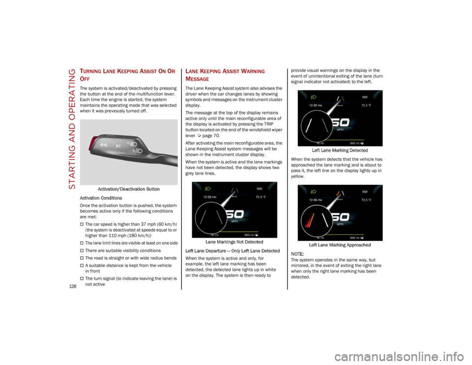
The system is activated/deactivated by pressing
the button at the end of the multifunction lever.
Each time the engine is started, the system
maintains the operating mode that was selected
when it was previously turned off.
Activation/Deactivation Button
Activation Conditions
Once the activation button is pushed, the system
becomes active only if the following conditions
are met:
The car speed is higher than 37 mph (60 km/h)
(the system is deactivated at speeds equal to or
higher than 110 mph (180 km/h))
The lane limit lines are visible at least on one side
There are suitable visibility conditions
The road is straight or with wide radius bends
A suitable distance is kept from the vehicle
in front
The turn signal (to indicate leaving the lane) is
not active
LANE KEEPING ASSIST WARNING
M
ESSAGE
The Lane Keeping Assist system also advises the
driver when the car changes lanes by showing
symbols and messages on the instrument cluster
display.
The message at the top of the display remains
active only until the main reconfigurable area of
the display is activated by pressing the TRIP
button located on the end of the windshield wiper
lever
Ú
page 70.
After activating the main reconfigurable area, the
Lane Keeping Assist system messages will be
shown in the instrument cluster display.
When the system is active and the lane markings
have not been detected, the display shows two
grey lane lines.
Lane Markings Not Detected
Left Lane Departure — Only Left Lane Detected
When the system is active and only, for
example, the left lane marking has been
detected, the detected lane lights up in white
on the display. The system is then ready to provide visual warnings on the display in the
event of unintentional exiting of the lane (turn
signal indicator not activated) to the left.
Left Lane Marking Detected
When the system detects that the vehicle has
approached the lane marking and is about to
pass it, the left line on the display lights up in
yellow.
Left Lane Marking Approached
NOTE:
The system operates in the same way, but
mirrored, in the event of exiting the right lane
when only the right lane marking has been
detected.
23_GU_OM_EN_USC_t.book Page 126
Page 132 of 268

STARTING AND OPERATING
130
REFUELING PROCEDURE
The fuel filler door is unlocked when the central
door locking system is unlocked. It is automat-
ically locked when the central locking system is
applied.
Opening The Fuel Filler Door
To refuel proceed as follows:
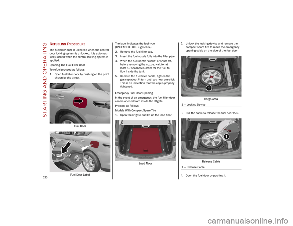
1. Open fuel filler door by pushing on the point shown by the arrow.
Fuel Door
Fuel Door Label The label indicates the fuel type
(UNLEADED FUEL = gasoline).
2. Remove the fuel filler cap.
3. Insert the fuel nozzle fully into the filler pipe.
4. When the fuel nozzle “clicks” or shuts off,
before removing the nozzle, wait for at
least 10 seconds in order for the fuel to
flow inside the tank.
5. Remove the fuel filler nozzle, tighten the gas cap about ¼ turn until you hear one click.
This is an indication that the cap is properly
tightened.
Emergency Fuel Door Opening
In the event of an emergency, the fuel filler door
can be opened from inside the liftgate.
Proceed as follows:
Models With Compact Spare Tire
1. Open the liftgate and lift up the load floor.
Load Floor 2. Unlock the locking device and remove the
compact spare tire to reach the emergency
opening cable on the side of the fuel door.
Cargo Area
3. Pull the cable to release the fuel door lock.
Release Cable
4. Open the fuel door by pushing it.
1 — Locking Device
1 — Release Cable
23_GU_OM_EN_USC_t.book Page 130
Page 143 of 268

141
(Continued)
DYNAMIC STEERING TORQUE (DST)
S
YSTEM
DST uses the integration of the Electronic
Stability Control (ESC) system with the electric
power steering to increase the safety level of the
whole vehicle.
In critical situations (e.g. braking on surfaces with
different grip conditions), the ESC system
influences the steering through the DST function
to implement an additional torque contribution
on the steering wheel in order to suggest the
most correct maneuver to the driver.
The coordinated action of the brakes and steering
increases the safety and control of the vehicle.
NOTE:
The DST feature is only meant to help the driver
realize the correct course of action through small
torques on the steering wheel, which means the
effectiveness of the DST feature is highly depen -
dent on the driver’s sensitivity and overall reac -
tion to the applied torque. It is very important to
realize that this feature will not steer the vehicle,
meaning the driver is still responsible for steering
the vehicle.
DRIVE TRAIN CONTROL (DTC) SYSTEM
Some models of this vehicle are equipped with an
All-Wheel Drive (AWD) system, which offers an
optimal drive for countless driving conditions and
road surfaces. The system reduces tire slipping to
a minimum, automatically redistributing the
torque to the front and rear wheels as needed. To maximize fuel savings, the vehicle with AWD
automatically passes to Rear-Wheel Drive (RWD)
when the road and environmental conditions are
such that they wouldn't cause the tires to slip.
When the road and environmental conditions
require better traction, the vehicle automatically
switches to AWD mode.
NOTE:
There may be a brief delay in shifting to
AWD mode after a tire slipping event occurs.
If the system failure symbol switches on, after
starting the engine or while driving, it means
that the AWD system is not working properly. If
the warning message activates frequently, it is
recommended to carry out the maintenance
operations.
ELECTRONIC STABILITY CONTROL (ESC)
S
YSTEM
The ESC system improves the directional control
and stability of the vehicle in various driving
conditions.
The ESC system corrects the vehicle’s understeer
and oversteer, distributing the brake force on the
appropriate wheels. The torque supplied by the
engine can also be reduced in order to maintain
control of the vehicle.
The ESC system uses sensors installed on the
vehicle to determine the path that the driver
intends to follow and compares it with the
vehicle’s effective path. When the real path
deviates from the desired path, the ESC system
intervenes to counter the vehicle’s oversteer or
understeer.
Oversteer occurs when the vehicle is turning
more than it should according to the angle of
the steering wheel.
Understeer occurs when the vehicle is turning
less than it should according to the angle of the
steering wheel.
System Intervention
The intervention of the system is indicated by the
flashing of the ESC Warning Light on the
instrument panel, to inform the driver that the
vehicle stability and grip are critical.
WARNING!
Electronic Stability Control (ESC) cannot
prevent the natural laws of physics from
acting on the vehicle, nor can it increase the
traction afforded by prevailing road
conditions. ESC cannot prevent accidents,
including those resulting from excessive
speed in turns, driving on very slippery
surfaces, or hydroplaning. ESC also cannot
prevent accidents resulting from loss of
vehicle control due to inappropriate driver
input for the conditions. Only a safe,
attentive, and skillful driver can prevent
accidents. The capabilities of an ESC
equipped vehicle must never be exploited in
a reckless or dangerous manner which could
jeopardize the user’s safety or the safety of
others.
23_GU_OM_EN_USC_t.book Page 141
Page 145 of 268

143
NOTE:
If the vehicle’s speed exceeds 6 mph (10 km/h),
but remains below 37 mph (60 km/h) and the
accelerator pedal is released, as soon as the
vehicle gets close to the set speed the HDC
system will automatically brake to keep the
vehicle at the set speed.
The driver can cancel HDC system intervention at
any time by pressing the accelerator pedal.
System Deactivation
The HDC system will be deactivated, but remain
available, if any of the following conditions are
met:
The vehicle is traveling on a downhill slope with
a gradient less than 8%, on a level surface, or
on an uphill grade.
PARK (P) mode is engaged.
Disabling The System
The system is disabled if any of the following
conditions are met:
The HDC switch is pressed.
Cruise Control/Adaptive Cruise Control is
activated.
A vehicle speed of 37 mph (60 km/h) is
exceeded.
System deactivation is shown by the icon on
the display turning off.
HILL START ASSIST (HSA) SYSTEM
HSA is an integral part of the Electronic Stability
Control (ESC) system that facilitates starting on
slopes, activating automatically in the following
cases:
Uphill: the vehicle is stationary on a road with a
gradient higher than 5%, the engine is running,
the brake is pressed, and the transmission is
in NEUTRAL (N) or a gear other than REVERSE
(R) is engaged.
Downhill: the vehicle is stationary on a road
with a gradient higher than 5%, the engine is
running, the brake is pressed, and the
transmission is in REVERSE.
When starting to move forward from a complete
stop, the ESC system control unit maintains the
braking pressure on the wheels until the engine
torque necessary for starting is reached, or in any
case for a maximum of two seconds, allowing
your right foot to be moved easily from the brake
pedal to the accelerator.
The system will automatically deactivate after two
seconds without starting, gradually releasing the
braking pressure. During this release stage, it is
possible to hear a typical mechanical brake
release noise, indicating the imminent movement
of the vehicle.
PANIC BRAKE ASSIST (PBA) SYSTEM
The PBA system is designed to improve the
vehicle’s braking capacity during emergency
braking.
The system detects emergency braking by
monitoring the speed and force with which the
brake pedal is pressed, and consequently applies
the optimal brake pressure. This can reduce the
braking distance; the PBA system therefore
complements the ABS.
Maximum assistance from the PBA system is
obtained by pressing the brake pedal very quickly.
In addition, the brake pedal should be pressed
continuously during braking, avoiding
intermittent presses, to get the most out of the
system. Do not reduce pressure on the brake
pedal until braking is no longer necessary.
WARNING!
HDC is only intended to assist the driver in
controlling vehicle speed when descending
hills. The driver must remain attentive to the
driving conditions and is responsible for
maintaining a safe vehicle speed.
WARNING!
There may be situations where the Hill Start
Assist (HSA) will not activate and slight rolling
may occur, such as on minor hills or with a
loaded vehicle, or while pulling a trailer. HSA is
not a substitute for active driving involvement.
It is always the driver’s responsibility to be
attentive to distance to other vehicles, people,
and objects, and most importantly brake
operation to ensure safe operation of the
vehicle under all road conditions. Your
complete attention is always required while
driving to maintain safe control of your vehicle.
Failure to follow these warnings can result in a
collision or serious personal injury.
23_GU_OM_EN_USC_t.book Page 143