Page 172 of 618

170
CV Owner's Manual_Europe_M52N20_en
4-1. Before driving
If you make no extreme correction with
the steering or brakes, your vehicle and
trailer should stabilize (if enabled, Trailer
Sway Control can also help to stabilize
the vehicle and trailer.).
●After the trailer swaying has stopped: • Stop in a safe place. Get all occupants out of the vehicle.
• Check the tires of the vehicle and the trailer.• Check the load in the trailer.
Make sure the load has not shifted. Make sure the tongue weight is appro-priate, if possible.
• Check the load in the vehicle. Make sure the vehicle is not over-loaded after occupants get in.
If you cannot find any problems, the
speed at which trailer swaying occurred
is beyond the limit of your particular
vehicle-trailer combination. Drive at a
lower speed to prevent instability.
Remember that swaying of the towing
vehicle-trailer increases as speed
increases.
Your vehicle will handle differently
when towing a trailer. In order to
avoid accident, death or serious
injury, keep the following in mind
when towing:
■Checking connections
between trailer and lights
Stop the vehicle and check the
operation of the connection
between the trailer and lights after
driving for a brief period as well as
before starting off.
■Practicing driving with a cou-
pled trailer
Get the feel for turning, stopping
and reversing with the trailer
coupled by practicing in an area
with no or light traffic.
When reversing with a coupled
trailer, hold the section of the
steering wheel nearest to you
and rotate clockwise to turn the
trailer left or counterclockwise to
turn it right. Always rotate a little
at a time to prevent steering
error. Have someone guide you
when reversing to lessen the risk
of an accident.
■Increasing vehicle-to-vehicle
distance
At a speed of 10 km/h (6 mph), the
distance to the vehicle running
ahead of you should be equivalent
to or greater than the combined
length of your vehicle and trailer.
Avoid sudden braking that may
cause skidding. Otherwise, the
vehicle may spin out of control. This
is especially true when driving on
wet or slippery road surfaces.
NOTICE
■When the rear bumper strength- ening material is aluminum
Ensure the steel bracket part does not
come directly in contact with that area.When steel and aluminum come into
contact, there is a reaction similar to corrosion, which will weaken the sec-tion concerned and may result in
damage. Apply a rust inhibitor to parts that will come in contact when attach-ing a steel bracket.
Guidance
Page 314 of 618

312
CV Owner's Manual_Europe_M52N20_en
5-1. Using the air conditioning system and defogger
5-1.Using the a ir c onditioning sys te m and de fog ger
*: If equipped
The illustrations below are for left-hand drive vehicles.
The button positions and shapes will differ for right-hand driv e vehicles.
The display and button positions will differ depending on the t ype of the
system.
Temperature control dial
Recirculated air mode/outside air mode dial
Airflow mode control dial
Rear window defogger and outside rear view mirror defoggers swi tch
Fan speed control knob
“A/C” switch
■Adjusting the temperature set-
ting
To adjust the temperature setting,
turn the temperature control dial
clockwise (warm) or counterclock-
wise (cool).
If “A/C” switch is not pressed, the sys-
tem will blow ambient temperature air
or heated air.
■Fan speed setting
To adjust the fan speed, turn the
fan speed control dial or knob
clockwise (increase) or counter-
clockwise (decrease).
Turning the dial or knob to
turns off the fan.
■Change the airflow mode
To select the air outlets, set the air
Manual air conditioning system*
Air conditioning controls
Page 319 of 618

317
5
CV Owner's Manual_Europe_M52N20_en
5-1. Using the air conditioning system and defogger
Interior features
Outside air mode switch
Recirculated air mode switch
Airflow mode control switch
Fan speed increases switch
Fan speed decreases switch
“FAST/ECO” switch
Rear window defogger and outside rear view mirror defoggers swi tch
Windshield defogger switch
Off switch
Automatic mode switch
Fan speed control dial
■Adjusting the temperature set-
ting
To adjust the temperature setting,
turn the temperature control dial
clockwise (warm) or counterclock-
wise (cool).
If “A/C” switch is not pressed, the sys-
tem will blow ambient temperature air
or heated air.
■Setting the fan speed
Vehicles with the DUAL mode
Operate the fan speed increases
switch to increase the fan speed
and the fan speed decreases
switch to decrease the fan speed.
Pressing the off switch to turns off the
fan.
Vehicles without the DUAL mode
To adjust the fan speed, turn the
fan speed control dial clockwise
(increase) or counterclockwise
(decrease).
■Change the airflow mode
Press the airflow mode control
switch.
The airflow mode changes as follows
each time the switch is pressed.
1 Upper body
2 Upper body and feet
Page 357 of 618

355
6
CV Owner's Manual_Europe_M52N20_en
6-3. Do-it-yourself maintenance
Maintenance and care
■Checking the engine oil
1 Park the vehicle on level
ground. After warming up the
engine and turning it off, wait
more than 5 minutes for the oil
to drain back into the bottom of
the engine.
2 Holding a rag under the end,
pull the dipstick out.
3 Wipe the dipstick clean.
4 Reinsert the dipstick fully.
5 Holding a rag under the end,
pull the dipstick out and check
the oil level.
Low
Normal
Excessive
The shape of the dipstick may differ
depending on the type of vehicle or
engine.
6 Wipe the dipstick and reinsert it
fully.
■Checking the oil type and pre-
paring the item needed
Make sure to check the oil type and
prepare the items needed before
adding oil.
Engine oil selection
P.450
Oil quantity (Low Full)
1.5 L (1.6 qt., 1.3 Imp. qt.)
Item
Clean funnel
■Adding engine oil
If the oil level is below or near the
low level mark, add engine oil of the
same type as that already in the
engine.
1 Remove the oil filler cap by turn-
ing it counterclockwise.
2 Add engine oil slowly, checking
the dipstick.
3 Install the oil filler cap by turning
it clockwise.
■Engine oil consumption
A certain amount of engine oil will be
Page 384 of 618
382
CV Owner's Manual_Europe_M52N20_en
6-3. Do-it-yourself maintenance
Under the driver’s side instru-
ment panel (left-hand drive vehi-
cles)
Remove the lid.
Make sure to push the claw when
removing/installing the lid.
Under the passenger’s side
instrument panel (right-hand
drive vehicles)
• Vehicles without a footwell lights
Remove the cover and then remove the
lid.
Make sure to push the claw when
removing/installing the lid.
• Vehicles with a footwell lights
Remove the cover.
Rotate the cover 90 degrees clockwise.
Page 389 of 618

387
6
CV Owner's Manual_Europe_M52N20_en
6-3. Do-it-yourself maintenance
Maintenance and care
■LED light bulbs
The lights other than the following lights
each consist of a number of LEDs. If any of the LEDs burn out, take your vehicle to any authorized Toyota retailer or
Toyota authorized repairer, or any reli- able repairer to have the light replaced.
●Headlights (bulb type)
●Front turn signal lights (bulb type)
●Rear turn signal lights (bulb type)
●License plate lights
●Back-up light (bulb type)
■Condensation build-up on the
inside of the lens
Temporary condensation build-up on the inside of the headlight lens does not
indicate a malfunction. Contact any authorized Toyota retailer or Toyota authorized repairer, or any reliable
repairer for more information in the fol- lowing situations:
●Large drops of water have built up on the inside of the lens.
●Water has built up inside the head-light.
■When replacing light bulbs
P. 3 8 4
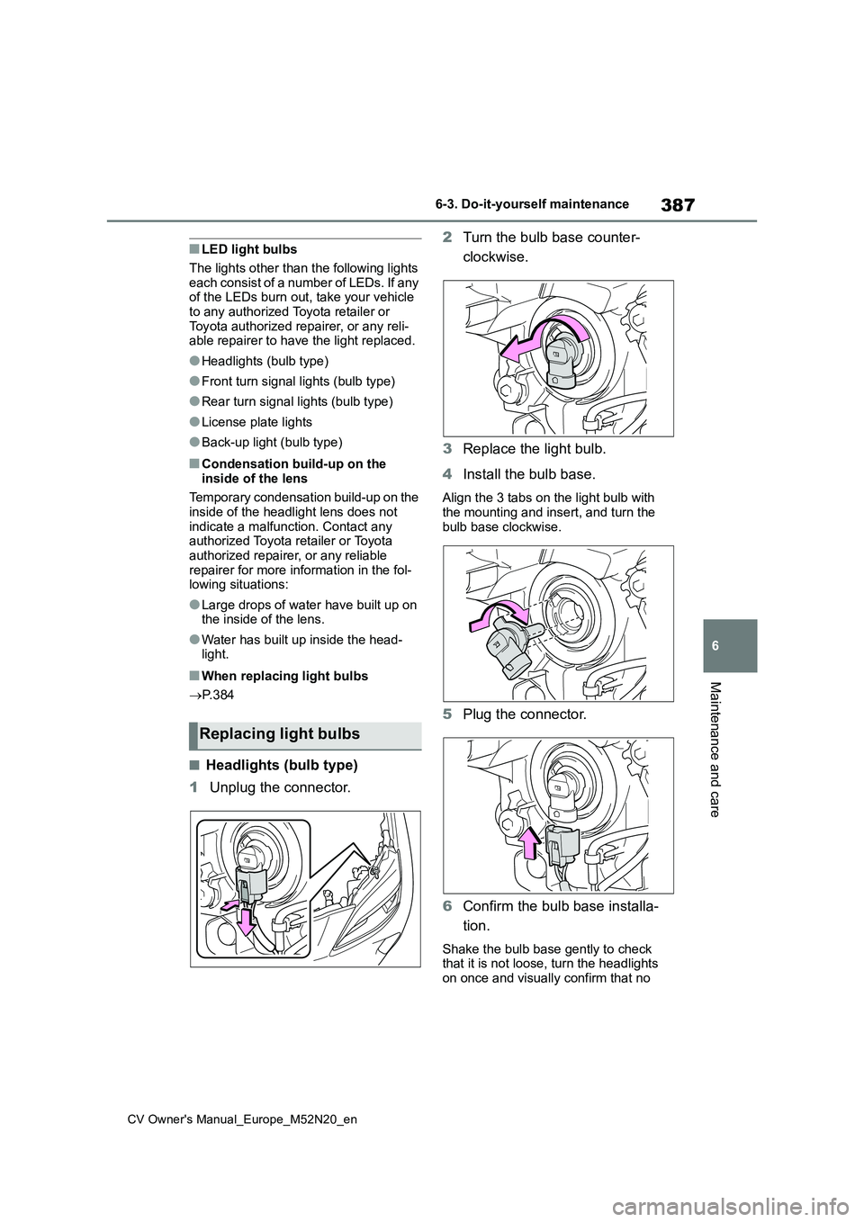
■Headlights (bulb type)
1 Unplug the connector.
2 Turn the bulb base counter-
clockwise.
3 Replace the light bulb.
4 Install the bulb base.
Align the 3 tabs on the light bulb with the mounting and insert, and turn the
bulb base clockwise.
5 Plug the connector.
6 Confirm the bulb base installa-
tion.
Shake the bulb base gently to check that it is not loose, turn the headlights
on once and visually confirm that no
Replacing light bulbs
Page 390 of 618
388
CV Owner's Manual_Europe_M52N20_en
6-3. Do-it-yourself maintenance
light is leaking through the mounting.
■Front turn signal lights (bulb
type)
1 Turn the bulb base counter-
clockwise.
2 Remove the light bulb.
3 When installing, reverse the
steps listed.
■Rear turn signal lights (bulb
type)
1 Open the back door.
2 Remove the 2 bolts and pull the
lamp assembly toward the rear
of the vehicle to remove it.
3 Turn the bulb base counter-
clockwise.
4 Remove the light bulb.
5 When installing the light bulb,
install by conducting 3 and 4
with the directions reversed.
6 Install the lamp assembly.
Align the guides and pins on the
lamp assembly with the mounting when
Page 392 of 618
390
CV Owner's Manual_Europe_M52N20_en
6-3. Do-it-yourself maintenance
2Remove the light bulb.
3 Install a new light bulb.
4 Install the lens.
1 Fit the lens into either the right
or left fitting portion.
2 Push the lens into place.
After installation, confirm that the lens is
properly installed by gently pulling it.
Fitting portion
■Back-up light (bulb type)
1 Open the back door and remove
the cover.
Press down on the notch on the cover
and remove the cover.
It is recommended for safeguarding to wrap the tip of the screwdriver with a
cloth, etc., in order to prevent scratches to the vehicle.
The back-up light (bulb type) position
will differ for right-hand drive vehicles. ( P.386)
2Turn the bulb base counter-
clockwise.