2022 TOYOTA TUNDRA HYBRID turn signal
[x] Cancel search: turn signalPage 250 of 618

2504-5. Using the driving support systems
Owners Manual_USA_M0C031_enwhen the lane centering function
is operating.
*2: May recognize the boundaries
between the asphalt and the side
o f t he r oa d, su ch as gr as s, s oil, or
the curb, to be road lanes
●Steering assist function
This function oper ates when all of
the following conditions are met in
addition to the operation conditions
for the lane departure alert function.
• Vehicle is not accelerated or decelerated by a fixed amount or
more.
• Steering wheel is not operated with a steering force level suitable
for changing lanes.
• ABS, VSC, TRAC and PCS are not operating.
• TRAC or VSC is not turned off.
• Hands off steering wheel warning is not displayed. ( P.251)
●Vehicle sway warning function
This function oper ates when all of
the following cond itions are met.
• Setting for “Sway Warning” in of the multi-information display is
set to “ON”. ( P.567)
• Vehicle speed is approximately 32
mph (50 km/h) or more.
• Width of traffic lane is approxi- mately 9.8 ft. ( 3 m) or more.
• No system malfunctions are
detected. ( P.252)
●Lane centering function
This function oper ates when all of
the following cond itions are met.
• LTA is turned on.
• Setting for “Lane Center” in of
the multi-informati on display is set
to “ON”. ( P.567)
• This function recognizes white
(yellow) lane lines or the position
of a preceding vehicle (except
when the preceding vehicle is
small, such as a motorcycle). • The dynamic radar cruise control
with full-speed ran ge is operating
in vehicle-to-vehicle distance con-
trol mode.
• Width of traffic lane is approxi- mately 10 to 13 ft. (3 to 4 m).
• Turn signal lever is not operated.
• Vehicle is not being driven around a sharp curve.
• No system malfunctions are detected. ( P.252)
• Vehicle does not accelerate or
decelerate by a fixed amount or
more.
• Steering wheel is not operated
with a steering force level suitable
for changing lanes.
• ABS, VSC, TRAC and PCS are
not operating.
• TRAC or VSC is not turned off.
• Hands off steering wheel warning is not displayed. ( P.251)
• The vehicle is being driven in the center of a lane.
• Steering assist function is not operating.
• When your vehicle is not towing a
trailer or during emergency tow-
ing.
■Temporary cancelation of func-
tions
●When operation conditions are no
longer met, a function may be
temporarily canceled. However,
when the operation conditions are
met again, operation of the func-
tion is automatically restored.
( P.249)
●If the operation conditions
( P.249) are no longer met while
the lane centering function is
operating, the steering wheel may
vibrate and the buzzer may sound
to indicate that the function has
been temporarily canceled. How-
ever, if the “Alert” customization
setting is set to , the system
will notify the driver by vibrating
the steering wheel instead of
sounding the buzzer.
Page 259 of 618
2594-5. Using the driving support systems
Owners Manual_USA_M0C031_en
4
Driving
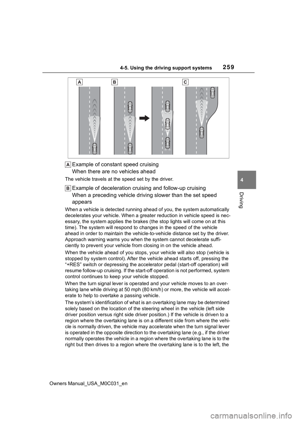
Example of constant speed cruising
When there are no vehicles ahead
The vehicle travels at the speed set by the driver.
Example of deceleration crui sing and follow-up cruising
When a preceding vehicle driving slower than the set speed
appears
When a vehicle is detected runni ng ahead of you, the system automatically
decelerates your vehicle. When a greater reduction in vehicle s peed is nec-
essary, the system applies the brakes (the stop lights will come on at this
time). The system will respond to changes in the speed of the vehicle
ahead in order to maintain the vehicle-to-vehicle distance set by the driver.
Approach warning warns you when the system cannot decelerate suffi-
ciently to prevent your vehicle from closing in on the vehicle ahead.
When the vehicle ahead of you st ops, your vehicle will also stop (vehicle is
stopped by system control). Afte r the vehicle ahead starts off, pressing the
“+RES” switch or depressing the accelerator pedal (start-off operation) will
resume follow-up cruising. If the start-off operation is not pe rformed, system
control continues to keep your vehicle stopped.
When the turn signal lever is ope rated and your vehicle moves to an over-
taking lane while driving at 50 mph (80 km/h) or more, the vehi cle will accel-
erate to help to overt ake a passing vehicle.
The system’s identification of what is an overtaking lane may be determined
solely based on the location of the steering wheel in the vehicle (left side
driver position versus right side driver position.) If the vehi cle is driven to a
region where the overtaking lane is on a different side from wh ere the vehi-
cle is normally driven, the vehicle may accelerate when the tur n signal lever
is operated in the opposite direction to the overtaking lane (e .g., if the driver
normally operates the vehicle in a region where the overtaking lane is to the
right but then drives to a region where the overtaking lane is to the left, the
Page 260 of 618
2604-5. Using the driving support systems
Owners Manual_USA_M0C031_envehicle may accelerate when the
right turn signal is activated).
Example of acceleration
When there are no longer any preceding vehicles driving slower
than the set speed
The system accelerates until the set speed is reached. The system then
returns to constan t speed cruising.
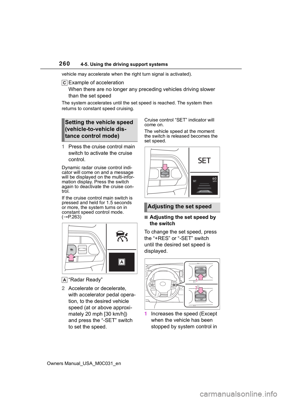
1Press the cruise control main
switch to activate the cruise
control.
Dynamic radar cruise control indi-
cator will come on and a message
will be displayed on the multi-infor-
mation display. Press the switch
again to deactivate the cruise con-
trol.
If the cruise cont rol main switch is
pressed and held for 1.5 seconds
or more, the syste m turns on in
constant speed control mode.
( P.263)
“Radar Ready”
2 Accelerate or decelerate,
with accelerator pedal opera-
tion, to the desired vehicle
speed (at or above approxi-
mately 20 mph [30 km/h])
and press the “-SET” switch
to set the speed.
Cruise control “SET” indicator will
come on.
The vehicle speed at the moment
the switch is released becomes the
set speed.
■Adjusting the set speed by
the switch
To change the set speed, press
the “+RES” or “-SET” switch
until the desired set speed is
displayed.
1 Increases the speed (Except
when the vehicle has been
stopped by system control in
Setting the vehicle speed
(vehicle-to-vehicle dis-
tance control mode)
Adjusting the set speed
Page 267 of 618

2674-5. Using the driving support systems
Owners Manual_USA_M0C031_en
4
Driving
Meter control switches
Turning the Blind Spot Monitor
on/off.
Outside rear view mirror indi-
cators
When a vehicle is detected in a
blind spot of the outside rear view
mirrors or approaching rapidly from
behind into a blind spot, the outside
rear view mirror indicator on the
detected side will illuminate. If the
turn signal lever is operated toward
the detected side, the outside rear
view mirror indicator flashes.
■Outside rear vie w mirror indica-
tor visibility
In strong sunlight, the outside rear
view mirror indicator may be difficult
to see.
■When “Blind Spot Monitor
Unavailable” is shown on the
multi-information display
Ice, snow, mud, etc., may be
attached to the rear bumper around
the sensors. ( P.269) The system
should return to normal operation
after removing the ice, snow, mud,
etc., from the rear bumper. Addition-
ally, the sensors may not operate
normally when drivin g in extremely
hot or cold environments.
BSM (Blind Spot Moni-
tor)
The Blind Spot Monitor is a
system that uses rear side
radar sensors installed on
the inner side of the rear
bumper on the left and right
side to assist the driver for
lane changing decision.
WARNING
■Cautions regarding the use of
the system
The driver is solely responsible for
safe driving. Always drive safely,
taking care to o bserve your sur-
roundings.
The Blind Spot Monitor is a sup-
plementary function which alerts
the driver that a v ehicle is in a
blind spot of the outside rear view
mirrors or is approaching rapidly
from behind into a blind spot. Do
not overly rely on the Blind Spot
Monitor. As the function cannot
judge if it is safe to change lanes,
over reliance could lead to an
accident resulting in death or seri-
ous injury.
As the system may not function
correctly under certain condi-
tions, the driver’s own visual con-
firmation of safety is necessary.
System components
Page 308 of 618

3084-5. Using the driving support systems
Owners Manual_USA_M0C031_en
The estimated course
lines move even
though the steering
wheel is straightThere is a malfunction in
the signals being output
by the steering sensor.Have the vehicle
inspected by your Toy-
ota dealer.
Guide lines are not dis-
playedThe tailgate is open.
Close the tailgate.
If this does not resolve
the symptom, have the
vehicle inspected by
your Toyota dealer.
is displayed
12-volt battery has
been reinstalled.
The steering wheel
has been moved while
the 12-volt battery was
being reinstalled.
12-volt battery power
is low.
The steering sensor
has been reinstalled.
There is a malfunction
in the signals being
output by the steering
sensor.
Stop the vehicle, and
turn the steering wheel
as far as it will go to the
left and right.
If this does not resolve
the symptom, have the
vehicle inspected by
your Toyota dealer.
SymptomLikely causeSolution
Page 436 of 618
4385-4. Using the other interior features
Owners Manual_USA_M0C031_en
Link® indicator to start flash-
ing).
■Before programming
●Install a new battery in the trans-
mitter.
●The battery side of the transmitter
must be pointed away from the
HomeLink
® buttons.
Press the appropriate Home-
Link
® button. The HomeLink®
indicator light should turn on.
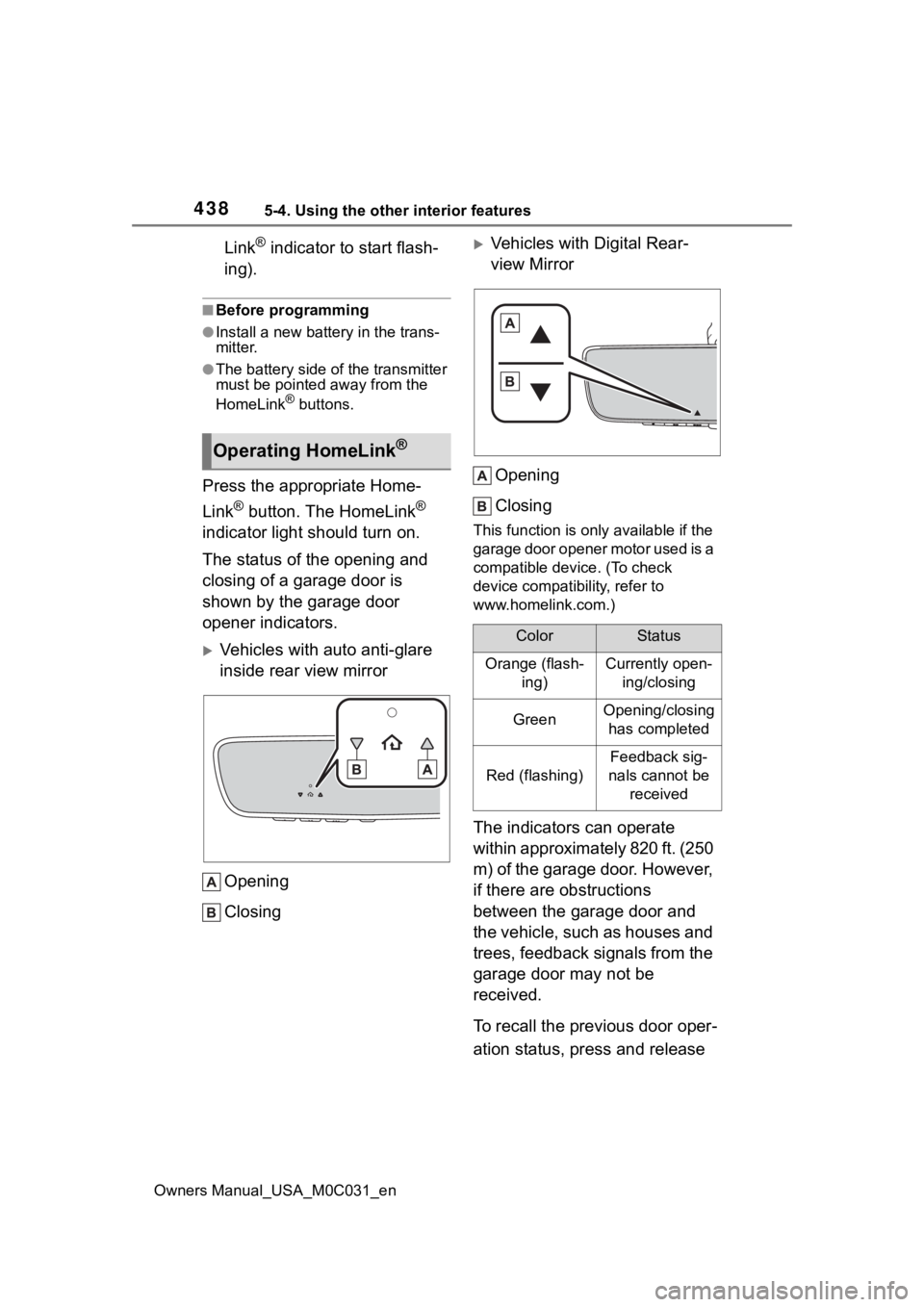
The status of the opening and
closing of a garage door is
shown by the garage door
opener indicators.
Vehicles with auto anti-glare
inside rear view mirror
Opening
Closing
Vehicles with Digital Rear-
view MirrorOpening
Closing
This function is only available if the
garage door opener motor used is a
compatible device. (To check
device compatibility, refer to
www.homelink.com.)
The indicators can operate
within approximately 820 ft. (250
m) of the garage door. However,
if there are obstructions
between the garage door and
the vehicle, such as houses and
trees, feedback signals from the
garage door may not be
received.
To recall the previous door oper-
ation status, press and release
Operating HomeLink®
ColorStatus
Orange (flash- ing)Currently open-ing/closing
GreenOpening/closing has completed
Red (flashing)
Feedback sig-
nals cannot be received
Page 467 of 618
4696-3. Do-it-yourself maintenance
Owners Manual_USA_M0C031_en
6
Maintenance and care
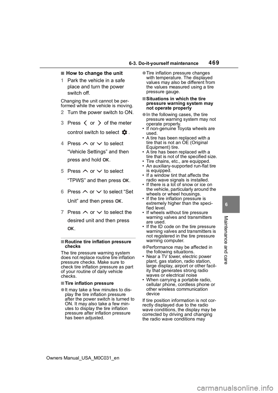
■How to change the unit
1 Park the vehicle in a safe
place and turn the power
switch off.
Changing the unit cannot be per-
formed while the vehicle is moving.
2Turn the power switch to ON.
3 Press or of the meter
control switch to select .
4 Press or to select
“Vehicle Settings” and then
press and hold .
5 Press or to select
“TPWS” and then press .
6 Press or to select “Set
Unit” and then press .
7 Press or to select the
desired unit and then press
.
■Routine tire inflation pressure
checks
The tire pressure warning system
does not replace routine tire inflation
pressure checks. Make sure to
check tire inflation pressure as part
of your routine of daily vehicle
checks.
■Tire inflation pressure
●It may take a few minutes to dis-
play the tire inflation pressure
after the power switch is turned to
ON. It may also take a few min-
utes to display the tire inflation
pressure after inflation pressure
has been adjusted.
●Tire inflation pressure changes
with temperature. The displayed
values may also be different from
the values measured using a tire
pressure gauge.
■Situations in which the tire
pressure warning system may
not operate properly
●In the following cases, the tire
pressure warning system may not
operate properly.
• If non-genuine Toyota wheels are
used.
• A tire has been replaced with a
tire that is not an OE (Original
Equipment) tire.
• A tire has been replaced with a
tire that is not of the specified size.
• Tire chains, etc. , are equipped.
• An auxiliary-support ed run-flat tire
is equipped.
• If a window tint that affects the radio wave signals is installed.
• If there is a lot of snow or ice on
the vehicle, particularly around the
wheels or wheel housings.
• If the tire inflation pressure is
extremely higher than the speci-
fied level.
• If wheels without tire pressure
warning valves and transmitters
are used.
• If the ID code on the tire pressure
warning valves and transmitters is
not registered in the tire pressure
warning computer.
●Performance may be affected in
the following situations.
• Near a TV tower, electric power plant, gas station, radio station,
large display, airpo rt or other facil-
ity that generates strong radio
waves or electrical noise
• When carrying a portable radio,
cellular phone, cordless phone or
other wireless communication
device
If tire position info rmation is not cor-
rectly displayed due to the radio
wave conditions, the display may be
corrected by driving and changing
the radio wave c onditions may
Page 488 of 618
4906-3. Do-it-yourself maintenance
Owners Manual_USA_M0C031_en
Check the wattage of the light
bulb to be replaced. ( P.548)
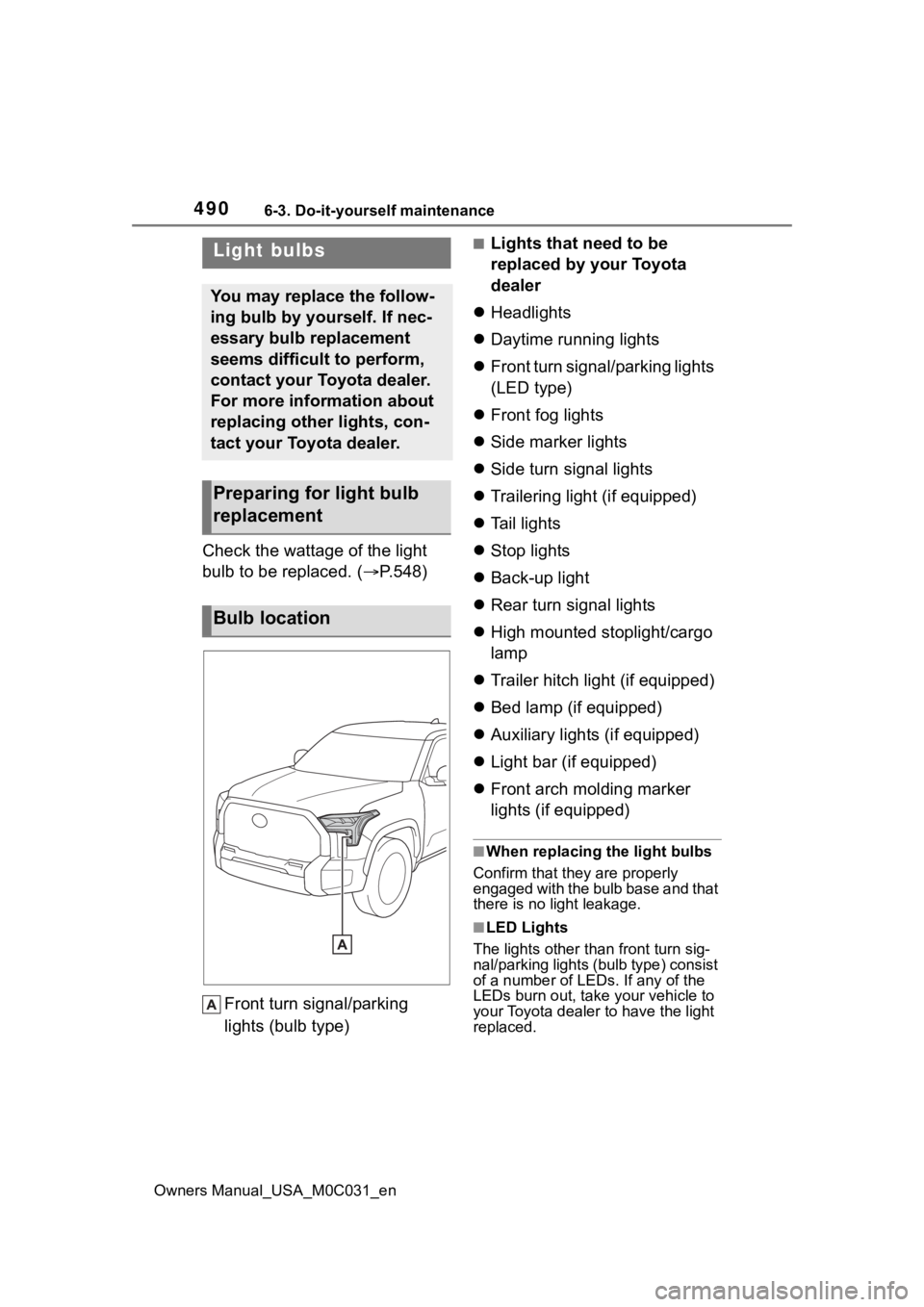
Front turn signal/parking
lights (bulb type)
■Lights that need to be
replaced by your Toyota
dealer
Headlights
Daytime running lights
Front turn signal/parking lights
(LED type)
Front fog lights
Side marker lights
Side turn signal lights
Trailering light (if equipped)
Tail lights
Stop lights
Back-up light
Rear turn signal lights
High mounted stoplight/cargo
lamp
Trailer hitch light (if equipped)
Bed lamp (if equipped)
Auxiliary lights (if equipped)
Light bar (if equipped)
Front arch molding marker
lights (if equipped)
■When replacing the light bulbs
Confirm that they are properly
engaged with the bulb base and that
there is no light leakage.
■LED Lights
The lights other than front turn sig-
nal/parking lights (b ulb type) consist
of a number of LEDs. If any of the
LEDs burn out, take your vehicle to
your Toyota dealer to have the light
replaced.
Light bulbs
You may replace the follow-
ing bulb by yourself. If nec-
essary bulb replacement
seems difficult to perform,
contact your Toyota dealer.
For more information about
replacing other lights, con-
tact your Toyota dealer.
Preparing for light bulb
replacement
Bulb location