Page 333 of 618
3334-5. Using the driving support systems
Owners Manual_USA_M0C031_en
4
Driving
Hitch zoom view
Bed view
●The area covered by the camera
is limited. Objects which are close
to either corner of the bumper or
under the bumper cannot be seen
on the screen.
●The area displayed on the screen
may vary depending on vehicle
orientation or road conditions.
●The camera uses a special lens.
The distance in the image dis-
played on the screen will differ
from the actual distance.
●In the rear split view, there is a
blind spot due to the size (length
and height) of the trailer.
●In the hitch zoom view, if a backlit
license plate is equipped it may be
reflected in the screen.
●In the bed zoom view, the section
near the cabin is a blind spot.
The cameras for the panoramic
view monitor are located as
shown in the illustrations.
Front camera
Side cameras
The camera
Page 382 of 618

3824-5. Using the driving support systems
Owners Manual_USA_M0C031_en
*: If equipped
1Select “Trailer Settings” from
( P.96) on the multi-
information display and add a
trailer according to the dis-
play. 2
Press the switch to turn the
system ON.
3 Continue or reselect the
trailer in the message dis-
played on the multi-informa-
tion display.
When the selected trailer is being
used for the first time, setup (cali-
bration) is nece ssary (→P.384).
Once calibration is completed, it is
retained for future use and the sys-
tem will automatically detect the
trailer.
The driver needs to change the
trailer selection when using a differ-
ent trailer. The system does not
automatically recognize the trailer
from the saved trailers list.
4 Once trailer is detected, shift
the shift lever to R to activate
Guidance mode.
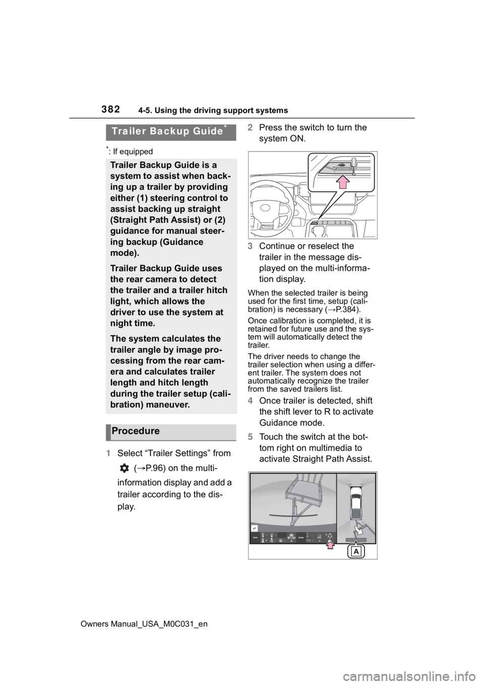
5 Touch the switch at the bot-
tom right on multimedia to
activate Straight Path Assist.
Trailer Backup Guide*
Trailer Backup Guide is a
system to assist when back-
ing up a trailer by providing
either (1) steering control to
assist backing up straight
(Straight Path Assist) or (2)
guidance for manual steer-
ing backup (Guidance
mode).
Trailer Backup Guide uses
the rear camera to detect
the trailer and a trailer hitch
light, which allows the
driver to use the system at
night time.
The system calculates the
trailer angle by image pro-
cessing from the rear cam-
era and calculates trailer
length and hitch length
during the trailer setup (cali-
bration) maneuver.
Procedure
Page 384 of 618

3844-5. Using the driving support systems
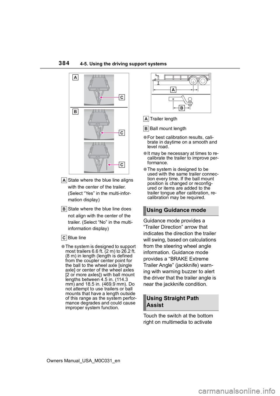
Owners Manual_USA_M0C031_enState where the blue line aligns
with the center of the trailer.
(Select “Yes” in the multi-infor-
mation display)
State where the blue line does
not align with the center of the
trailer. (Select “
No” in the multi-
information display)
Blue line
●The system is designed to support
most trailers 6.6 ft. (2 m) to 26.2 ft.
(8 m) in length (length is defined
from the coupler c enter point for
the ball to the wheel axle [single
axle] or center o f the wheel axles
[2 or more axles]) with ball mount
lengths between 4.5 in. (114.3
mm) and 18.5 in. ( 469.9 mm). Do
not attempt to use trailers or ball
mounts that have a length outside
of this range as t he system perfor-
mance degrades and could cause
improper system function. Trailer length
Ball mount length
●For best calibration results, cali-
brate in daytime on a smooth and
level road.
●It may be necessary at times to re-
calibrate the trailer to improve per-
formance.
●The system is designed to be
used with the same trailer connec-
tion every time. If the ball mount
position is changed or reconfig-
ured or items are added to the
trailer tongue
after calibration, re-
calibration may be required.
Guidance mode provides a
“Trailer Direction” arrow that
indicates the direction the trailer
will swing, based on calculations
from the steering wheel angle
information. Guidance mode
provides a “BRAKE Extreme
Trailer Angle” (jackknife) warn-
ing with warning buzzer to alert
the driver that the trailer angle is
near the jackknife condition.
Touch the switch at the bottom
right on multimedia to activate
Using Guidance mode
Using Straight Path
Assist
Page 416 of 618
4185-3. Using the storage features
Owners Manual_USA_M0C031_en
Ty p e A
Ty p e B
Dimensions of the wood that is
prepared:
Prepare a 2 8 wood plank with
the following dimensions.
62.2 in (1580 mm)
60.7 in (1541 mm)
6 degree
Measure dimension and on
your vehicle to ensure accurate
length based on v ehicle variation.
■Horizontal position
A 2 8 wood plank can be placed
in the deck board grooves.
Prepare the board by measuring
the length with the actual vehicle
according to the position it is to
be placed.
Insertion position:
Type A
Type B
Dimensions:
Page 417 of 618

4195-3. Using the storage features
Owners Manual_USA_M0C031_en
5
Interior features
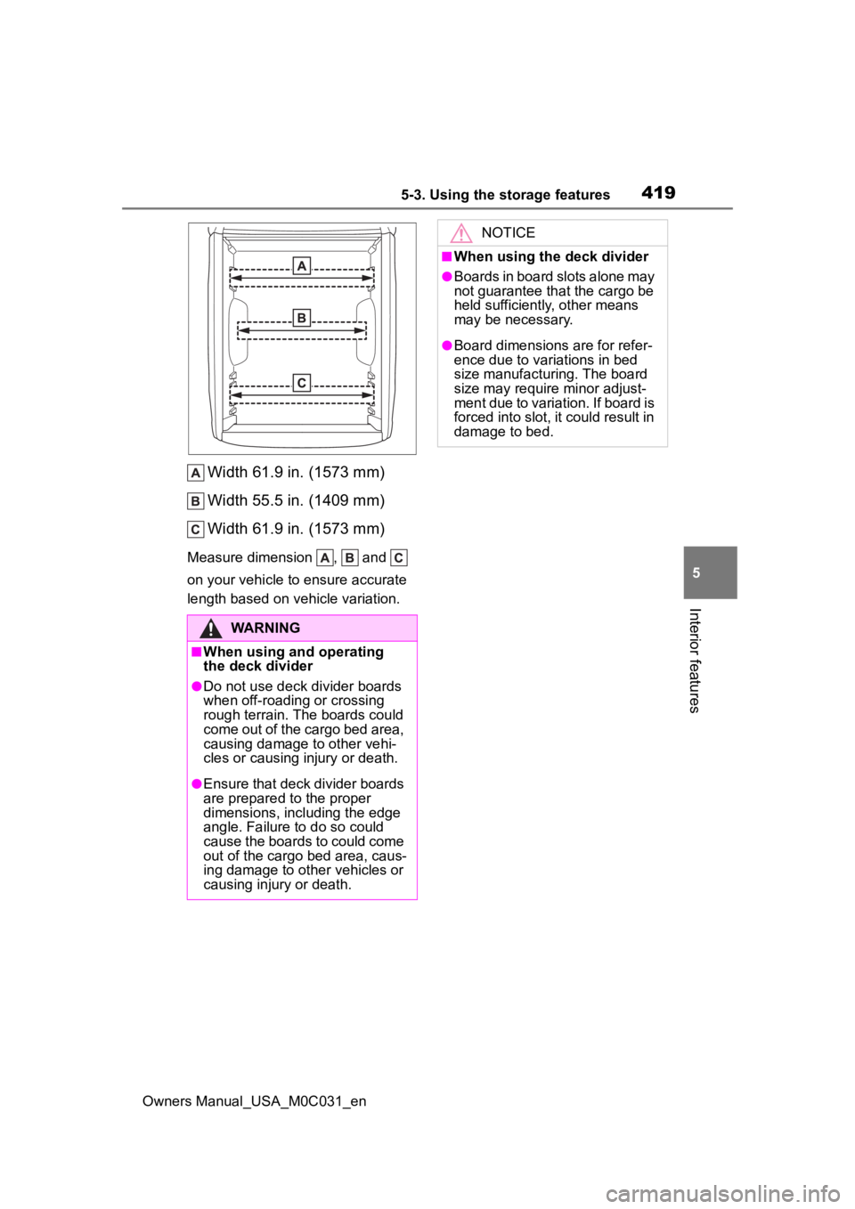
Width 61.9 in. (1573 mm)
Width 55.5 in. (1409 mm)
Width 61.9 in. (1573 mm)
Measure dimension , and
on your vehicle to ensure accurate
length based on v ehicle variation.
WARNING
■When using and operating
the deck divider
●Do not use deck divider boards
when off-roading or crossing
rough terrain. The boards could
come out of the cargo bed area,
causing damage to other vehi-
cles or causing injury or death.
●Ensure that deck divider boards
are prepared to the proper
dimensions, including the edge
angle. Failure to do so could
cause the boards to could come
out of the cargo bed area, caus-
ing damage to other vehicles or
causing injury or death.
NOTICE
■When using the deck divider
●Boards in board slots alone may
not guarantee that the cargo be
held sufficiently, other means
may be necessary.
●Board dimensions are for refer-
ence due to variations in bed
size manufacturing. The board
size may require minor adjust-
ment due to variation. If board is
forced into slot, it could result in
damage to bed.
Page 538 of 618
5408-1. Specifications
Owners Manual_USA_M0C031_en
8-1.Specifications
*1: Unladen vehicles
*2: Short Bed type
*3: Standard Bed type
*4: 265/70R18 tires
*5: 265/60R20 tires
*6: 285/65R18 tires
*7: 265/50R22 tires
Maintenance data (fuel, oil level, etc.)
Dimensions and weight
Overall length233.6 in. (5932 mm)*2
245.6 in. (6237 mm)*3
Overall width80.0 in. (2031 mm)
Overall height*1
2WD
76.7 in. (1949 mm)*2, 4
76.8 in. (1952 mm)*2, 5
76.9 in. (1953 mm)*3, 4
77.0 in. (1955 mm)*3, 5
4WD
77.3 in. (1964 mm)*2, 7
77.4 in. (1966 mm)*2, 4
77.5 in. (1968 mm)*2, 5
77.5 in. (1968 mm)*3, 4
77.6 in. (1969 mm)*3, 5
77.8 in. (1975 mm)*2, 6
Wheelbase145.7 in. (3700 mm)*2
157.7 in. (4005 mm)*3
Front tread
2WD68.4 in. (1737 mm)
4WD68.1 in. (1729 mm)*4, 5, 7
68.5 in. (1739 mm)*6
Rear tread68.4 in. (1737 mm)