2022 TOYOTA SUPRA warning lights
[x] Cancel search: warning lightsPage 169 of 498

167
3
3-1. CONTROLS
CONTROLS
Steering system
The steering system may
be faulty.
Have the system checked
by any authorized Toyota
retailer or Toyota author-
ized repairer, or any relia-
ble repairer.
Emissions
Engine malfunction.
Have the vehicle checked
by any authorized Toyota
retailer or Toyota author-
ized repairer, or any relia-
ble repairer.
Socket for on-board diag-
nosis, see page 332.
Rear fog light
Rear fog light is switched
on.
Rear fog light, see page
190.
Green lights
Turn indicator
The turn indicator is
switched on.
If the indicator lamp
flashes more rapidly than
usual, a turn signal light
has failed.
Turn indicators, see page
150.
Side lights
The side lights are
switched on.
Side lights/low-beam
headlights, see page 185.
Low-beam headlights
Low-beam headlights are
switched on.
Side lights/low-beam
headlights, see page 185.
Lane Departure Warning
If the indicator lamp is illu-
minated: the system is
switched on. At least one
lane marking has been
detected and warnings
can be issued on at least
one side of the vehicle.
Lane Departure Warning,
see page 216.
Page 170 of 498

1683-1. CONTROLS
The current fill level of the fuel tank
is displayed.
The angle of the vehicle may cause
the display to fluctuate.
For notes on refuelling, see page
290.
It is vital to avoid engine speeds in
the red warning zone. In this zone,
the fuel supply is interrupted to pro-
tect the engine.
Depending on the equipment, the
shift lights on the revolution counter
indicate the maximum shift point at
which the best possible accelera-
tion can be achieved.
When the selected driving mode is
sport mode, a shift light will be dis-
played.
1 Select SPORT using the sport
mode switch.
2 Activate manual mode of the
transmission.
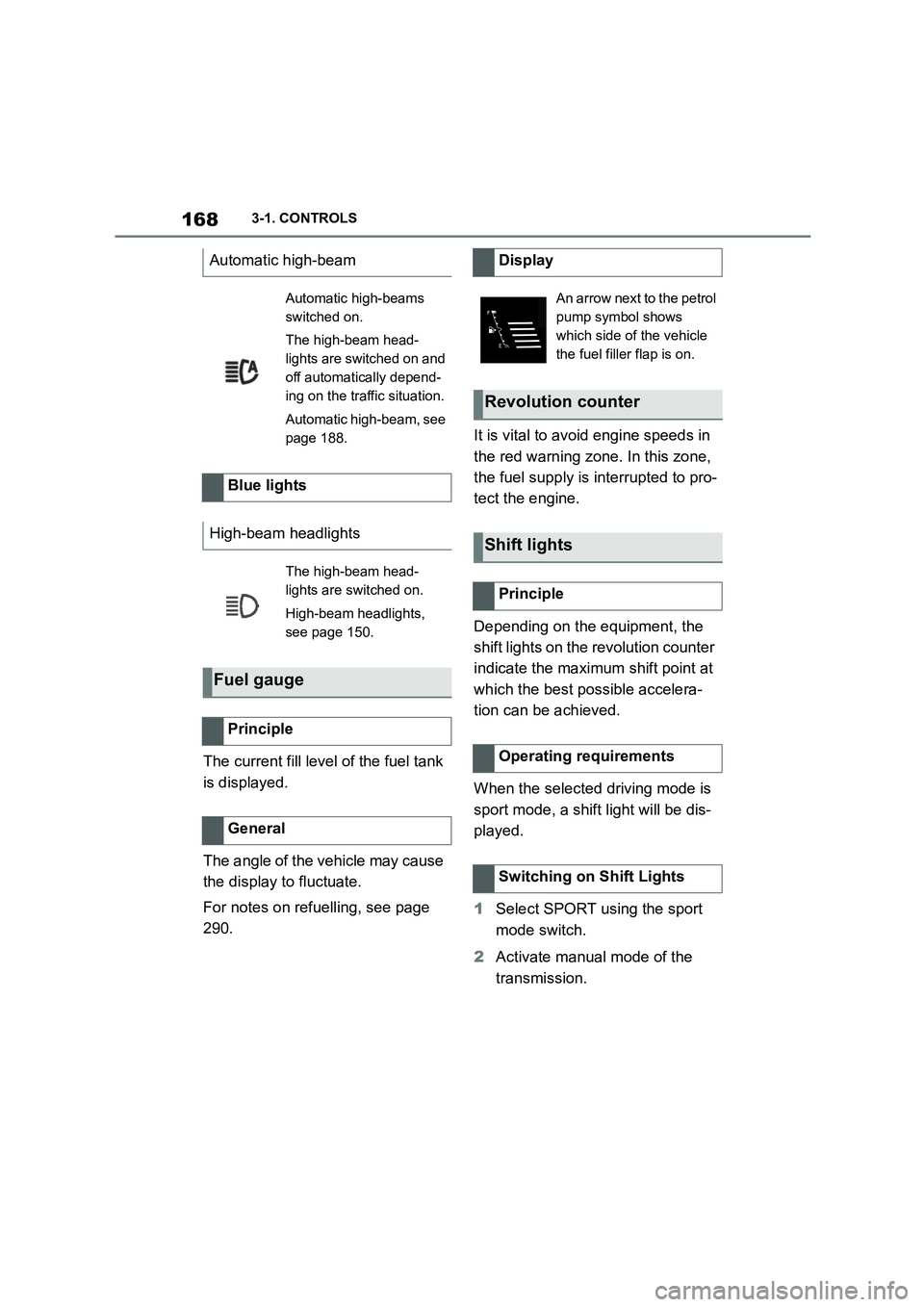
Automatic high-beam
Automatic high-beams
switched on.
The high-beam head-
lights are switched on and
off automatically depend-
ing on the traffic situation.
Automatic high-beam, see
page 188.
Blue lights
High-beam headlights
The high-beam head-
lights are switched on.
High-beam headlights,
see page 150.
Fuel gauge
Principle
General
Display
An arrow next to the petrol
pump symbol shows
which side of the vehicle
the fuel filler flap is on.
Revolution counter
Shift lights
Principle
Operating requirements
Switching on Shift Lights
Page 226 of 498

2243-1. CONTROLS
number of premature warnings
about critical situations.
Depending on the equipment and
the nationalmarket version, the
Rear Collision Prevention can
respond to vehicles approaching
from behind.
Radar sensors monitor the area
behind the vehicle.
If a vehicle is approaching from
behind at a relevant speed, the sys-
tem can respond as follows:
The hazard warning lights are
switched on if appropriate.
PreCrash functions are trig-
gered if appropriate.
The system is controlled using the
following sensors:
• Side radar sensors, rear.
For further information:
Sensors of the vehicle, see page
50.
The system is automatically acti-
vated at the start of each journey.
The system is deactivated in the
following situations:
Prevention of rear collision
Principle
General
Safety notes
WA R N I N G
The system does not relieve you of
your personal responsibility to assess the visibility conditions and traffic situ-
ation correctly. There is a danger of
accidents. Adapt your driving style to the traffic conditions. Observe the
traffic situation and intervene actively
if the situation warrants it.
WA R N I N G
Displays and warnings do not relieve
you of your personal responsibility.
System limitations can mean that warnings or system responses are
not issued or are issued too late,
incorrectly or without justification. There is a danger of accidents. Adapt
your driving style to the traffic condi-
tions. Observe the traffic situation and intervene actively if the situation war-
rants it.
Overview
Sensors
Switching on/off
Page 227 of 498

225
3
3-1. CONTROLS
CONTROLS
When reversing.
For further information:
• Radar sensors, see page 50.
The system may ha ve restricted
functionality in the following situa-
tions:
The speed of the approaching
vehicle is much faster than your
own speed.
The approaching vehicle is
approaching slowly.
The brake lights flash to warn road
users behind the vehicle that emer-
gency braking is being performed.
Normal braking: brake lights illu-
minate.
Heavy braking: brake lights flash.
Shortly before the vehicle comes to
a standstill, th e hazard warning
lights are activated.
To switch off the hazard warning
lights:
Accelerate.
Press the hazard warning lights
button.
The system can automatically bring
the vehicle to a standstill in certain
accident situations without the
involvement of the driver. The risk
of a further collision and its conse-
quences can thereby be reduced.
After the vehicle has come to a halt,
the brake is released automatically.
In certain situations, it may be nec-
essary to bring the vehicle to a
standstill more quickly than is pos-
sible with automatic braking.
To do so, brake quickly and firmly.
For a brief period, the braking pres-
sure will be higher than that
System limits
System limits of the sensors
Functional limitations
Emergency brake lights
Principle
General
Autonomous Emergency
Braking
Principle
At a standstill
Harder vehicle braking
Page 301 of 498

299
5
5-1. MOBILITY
MOBILITY
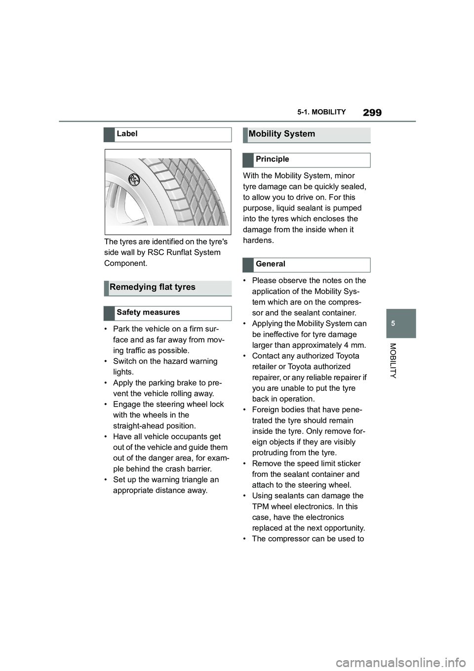
The tyres are identified on the tyre's
side wall by RSC Runflat System
Component.
• Park the vehicle on a firm sur-
face and as far away from mov-
ing traffic as possible.
• Switch on the hazard warning
lights.
• Apply the parking brake to pre-
vent the vehicle rolling away.
• Engage the steering wheel lock
with the wheels in the
straight-ahead position.
• Have all vehicle occupants get
out of the vehicle and guide them
out of the danger area, for exam-
ple behind the crash barrier.
• Set up the warning triangle an
appropriate distance away.
With the Mobility System, minor
tyre damage can be quickly sealed,
to allow you to drive on. For this
purpose, liquid sealant is pumped
into the tyres which encloses the
damage from the inside when it
hardens.
• Please observe the notes on the
application of the Mobility Sys-
tem which are on the compres-
sor and the sealant container.
• Applying the Mobility System can
be ineffective for tyre damage
larger than approximately 4 mm.
• Contact any authorized Toyota
retailer or Toyota authorized
repairer, or any reliable repairer if
you are unable to put the tyre
back in operation.
• Foreign bodies that have pene-
trated the tyre should remain
inside the tyre. Only remove for-
eign objects if they are visibly
protruding from the tyre.
• Remove the speed limit sticker
from the sealant container and
attach to the steering wheel.
• Using sealants can damage the
TPM wheel electronics. In this
case, have the electronics
replaced at the next opportunity.
• The compressor can be used to
Label
Remedying flat tyres
Safety measures
Mobility System
Principle
General
Page 302 of 498

3005-1. MOBILITY
check the tyre inflation pressure.
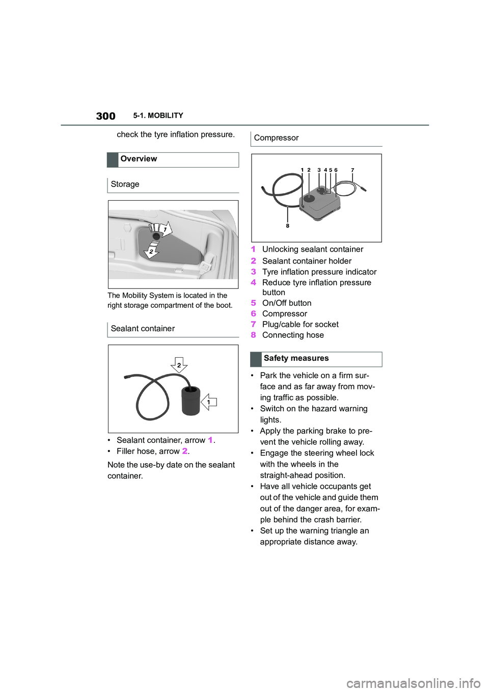
The Mobility System is located in the
right storage compartment of the boot.
• Sealant container, arrow 1.
• Filler hose, arrow 2.
Note the use-by date on the sealant
container.
1 Unlocking sealant container
2 Sealant container holder
3 Tyre inflation pressure indicator
4 Reduce tyre inflation pressure
button
5 On/Off button
6 Compressor
7 Plug/cable for socket
8 Connecting hose
• Park the vehicle on a firm sur-
face and as far away from mov-
ing traffic as possible.
• Switch on the hazard warning
lights.
• Apply the parking brake to pre-
vent the vehicle rolling away.
• Engage the steering wheel lock
with the wheels in the
straight-ahead position.
• Have all vehicle occupants get
out of the vehicle and guide them
out of the danger area, for exam-
ple behind the crash barrier.
• Set up the warning triangle an
appropriate distance away.
Overview
Storage
Sealant container
Compressor
Safety measures
Page 317 of 498

315
5
5-1. MOBILITY
MOBILITY
cial coding. The bolts can only be
released with the adapter that
matches the coding.
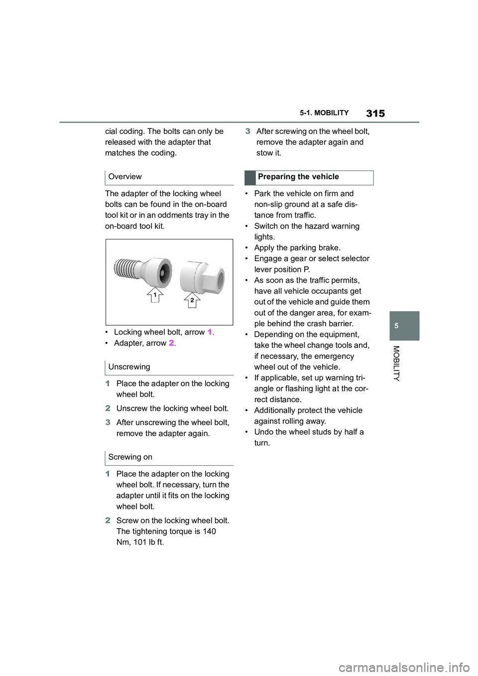
The adapter of the locking wheel
bolts can be found in the on-board
tool kit or in an oddments tray in the
on-board tool kit.
• Locking wheel bolt, arrow 1.
• Adapter, arrow 2.
1 Place the adapter on the locking
wheel bolt.
2 Unscrew the locking wheel bolt.
3 After unscrewing the wheel bolt,
remove the adapter again.
1 Place the adapter on the locking
wheel bolt. If necessary, turn the
adapter until it fi ts on the locking
wheel bolt.
2 Screw on the locking wheel bolt.
The tightening torque is 140
Nm, 101 lb ft.
3 After screwing on the wheel bolt,
remove the adapter again and
stow it.
• Park the vehicle on firm and
non-slip ground at a safe dis-
tance from traffic.
• Switch on the hazard warning
lights.
• Apply the parking brake.
• Engage a gear or select selector
lever position P.
• As soon as the traffic permits,
have all vehicle occupants get
out of the vehicle and guide them
out of the danger area, for exam-
ple behind the crash barrier.
• Depending on the equipment,
take the wheel change tools and,
if necessary, the emergency
wheel out of the vehicle.
• If applicable, set up warning tri-
angle or flashing light at the cor-
rect distance.
• Additionally protect the vehicle
against rolling away.
• Undo the wheel studs by half a
turn.
Overview
Unscrewing
Screwing on
Preparing the vehicle
Page 352 of 498

3505-1. MOBILITY
This chapter describes all standard,
country-specific and special equip-
ment available for the model series.
It may therefore describe equip-
ment and functions which are not
installed in your vehicle, for exam-
ple on account of the special equip-
ment selected or the country
specification. This also applies to
safety-relevant functions and sys-
tems. Please comply with the rele-
vant laws and regulations when
using the corresponding functions
and systems.
Breakdown Assist
Vehicle equipment
If a malfunction occurs
while driving
WA R N I N G
If a malfunction occurs while driving,
immediately stop the vehicle in a safe
place.
If a warning light illuminates or flashes, or a warning message is dis-
played, immediately stop the vehicle
in a safe place. Do not open the hood to inspect the engine, as doing so
may lead to serious injury, such as
steam burns. If a warning message is displayed, perform the necessary pro-
cedures according to the displayed
message or explanation in the owner’s manual.
These warning messages indicate that a malfunction has occurred in a
system or function of the vehicle. If
you continue to drive the vehicle, the engine may stop suddenly, possibly
leading to an accident. Also, even if
no warning lights are illuminated or messages are displayed, if any
abnormal sounds, smells or vibrations
are detected, or of the engine stops suddenly, refrain from opening the
hood to inspect the engine and con-
sult any authorized Toyota retailer or Toyota authorized repairer, or any reli-
able repairer.
WA R N I N G
If you hear a loud noise or feel some-
thing impact the underside of the vehicle while driving, immediately
stop the vehicle in a safe place.
After stopping the vehicle in a safe
place, check the underside of the
vehicle for any leaking brake fluid, oil or fuel. If any fluid is leaking, stop
driving immediately and have the
vehicle inspected by any authorized Toyota retailer or Toyota authorized
repairer, or any reliable repairer.