2022 TOYOTA RAV4 window
[x] Cancel search: windowPage 582 of 748

5827-3. Do-it-yourself maintenance
■When rotating the tires (vehi-
cles with tire pressure warning
system)
Make sure that the engine switch is
OFF. If the tires are rotated while
the engine switch i s in ON, the tire
position informa tion will not be
updated. If this accidentally occurs,
either turn the engine switch to OFF
and then to ON, or initialize the sys-
tem after checking that the tire pres-
sure is properly adjusted.
Your vehicle is equipped with a
tire pressure warning system
that uses tire pressure warning
valves and transmitters to detect
low tire inflation pressure before
serious problems arise.
If the tire pressure drops
below a predetermined level,
the driver is warned by a
screen display and a warning
light. ( P.628)
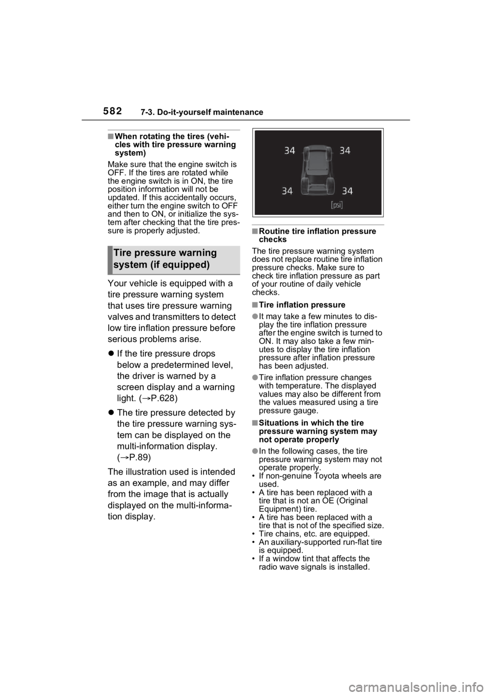
The tire pressure detected by
the tire pressure warning sys-
tem can be displayed on the
multi-information display.
( P.89)
The illustration used is intended
as an example, and may differ
from the image that is actually
displayed on the multi-informa-
tion display.
■Routine tire inflation pressure
checks
The tire pressure warning system
does not replace routine tire inflation
pressure checks . Make sure to
check tire inflation pressure as part
of your routine o f daily vehicle
checks.
■Tire inflation pressure
●It may take a few minutes to dis-
play the tire inflation pressure
after the engine switch is turned to
ON. It may also take a few min-
utes to display the tire inflation
pressure after infl ation pressure
has been adjusted.
●Tire inflation pressure changes
with temperature. The displayed
values may also be different from
the values measured using a tire
pressure gauge.
■Situations in which the tire
pressure warning system may
not operate properly
●In the following cases, the tire
pressure warning system may not
operate properly.
• If non-genuine Toyota wheels are used.
• A tire has been replaced with a tire that is not an OE (Original
Equipment) tire.
• A tire has been replaced with a tire that is not of the specified size.
• Tire chains, etc. are equipped.
• An auxiliary-support ed run-flat tire
is equipped.
• If a window tint that affects the radio wave signals is installed.
Tire pressure warning
system (if equipped)
Page 595 of 748

5957-3. Do-it-yourself maintenance
7
Maintenance and care
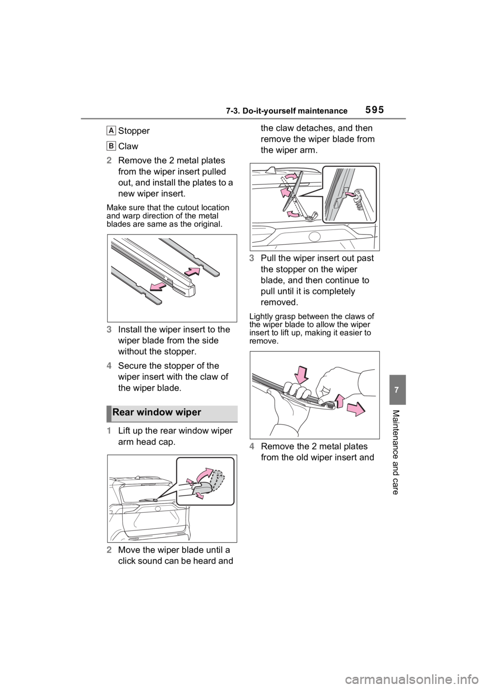
Stopper
Claw
2 Remove the 2 metal plates
from the wiper insert pulled
out, and install the plates to a
new wiper insert.
Make sure that the cutout location
and warp direction of the metal
blades are same as the original.
3Install the wiper insert to the
wiper blade from the side
without the stopper.
4 Secure the stopper of the
wiper insert with the claw of
the wiper blade.
1 Lift up the rear window wiper
arm head cap.
2 Move the wiper blade until a
click sound can be heard and the claw detaches, and then
remove the wiper blade from
the wiper arm.
3 Pull the wiper insert out past
the stopper on the wiper
blade, and then continue to
pull until it is completely
removed.
Lightly grasp between the claws of
the wiper blade to allow the wiper
insert to lift up, making it easier to
remove.
4 Remove the 2 metal plates
from the old wiper insert and
Rear window wiper
A
B
Page 597 of 748

5977-3. Do-it-yourself maintenance
7
Maintenance and care
■If the key battery is depleted
The following symptoms may occur:
●The smart key system (if
equipped) and wireless remote
control will not function properly.
●The operational range will be
reduced.
Prepare the following before
replacing the battery:
Flathead screwdriver
Small flathead screwdriver
Lithium battery CR2032
■Use a CR2032 lithium battery
●Batteries can be purchased at
your Toyota dealer, local electrical
appliance shops or camera stores.
●Replace only with the same or
equivalent type recommended by
the manufacturer.
●Dispose of used batteries accord-
ing to the local laws.
Vehicles without smart key
system
1 Remove the cover.
Use a screwdriver of an appropriate
size. Forcedly prying may cause
the cover damaged.
NOTICE
■To prevent damage
●Be careful not to damage the
claws when replacing the wiper
insert.
●After the wiper blade is removed
from the wiper arm, place a
cloth, etc., between the rear
window and wiper arm to pre-
vent damage to the rear win-
dow.
●Be sure not to pull excessively
on the wiper insert or deform its
metal plates.
Wireless remote con-
trol/electron ic key bat-
tery
Replace the battery with a
new one if it is depleted.
Items to prepare
Replacing the battery
Page 613 of 748

6138-1. Essential information
8
When trouble arises
Vehicles with smart key sys-
tem
Press and hold the engine switch
for 2 consecutive seconds or more,
or press it briefly 3 times or more in
succession.
5Stop the vehicle in a safe
place by the road.
If the door can be opened,
open the door and exit the
vehicle.
If the door can not be opened,
open the window using the
power window switch and
ensure an escape route.
If the window can be opened,
exit the vehicle through the
window.
If the door and window cannot
be opened due to the rising
water, remain calm, wait until
the water level inside the
vehicle rises to the point that
the water pressure inside of
the vehicle equals the water
pressure outside of the vehi-
cle and then open the door
after waiting for the rising
water to enter the vehicle, and
exit the vehicle. When the
WARNING
■If the engine has to be turned
off while driving
●Power assist for the brakes and
steering wheel will be lost, mak-
ing the brake pedal harder to
depress and the steering wheel
heavier to turn. Decelerate as
much as possible before turning
off the engine.
●Vehicles without smart key sys-
tem: Never attempt to remove
the key, as doing so will lock the
steering wheel.
If the vehicle is sub-
merged or water on
the road is rising
This vehicle is not designed
to be able to drive on roads
that are deeply flooded with
water. Do not drive on roads
where the roads may be
submerged or the water
may be rising. It is danger-
ous to remain in the vehicle,
if it anticipated that the vehi-
cle will be flooded or set a
drift. Remain calm and fol-
low the following.
Page 614 of 748

6148-1. Essential information
outside water level exceeds
half the height of the door, the
door cannot be opened from
the inside due to water pres-
sure.
■Water level exceeds the floor
When the water level exceeds the
floor and time has passed, the elec-
trical equipment will get damaged,
the power windows will not operate,
the engine stops, and the vehicle
may not be able to get moving.
■Using an emergency escape
hammer*
Laminated glass is used in the wind-
shield on this vehicle. Laminated
glass cannot be shattered with an
emergency hammer
*. Tempered
glass is used in the windows on this
vehicle.
*: Contact your Toyota dealer or
aftermarket accessory manufac-
turer for further information about
an emergency hammer.
WARNING
■Caution while driving
Do not drive on roads where the
roads may be submerged or the
water may be rising. Otherwise
the vehicle may be damaged and
cannot move, as well as become
flooded and set a drift, which may
lead to death.
Page 649 of 748

6498-2. Steps to take in an emergency
8
When trouble arises
Use the mechanical key
(P.106) in order to perform the
following operations.
1 Locks all the doors
2 Unlocks the door
Turning the key rearward unlocks
the driver’s door. Turning the key
once again within 5 seconds
unlocks the other doors.
■Key linked functions
1 Closes the windows and the
moon roof
*1 or panoramic moon
roof
*1 (turn and hold)*2
2 Opens the windows and the
moon roof
*1 or panoramic moon
roof
*1 (turn and hold)*2
*1
: If equipped
*2: These settings must be custom- ized at your Toyota dealer.
1 Ensure that the shift lever is
in P and depress the brake
pedal.
2 Touch the Toyota emblem
side of the electronic key to
the engine switch.
When the electronic key is
detected, a buzzer sounds and the
engine switch will turn to ON.
When the smart key system is
deactivated in customization set-
ting, the engine switch will turn to
ACC.
Locking and unlocking
the doorsWARNING
■When using the mechanical
key and operating the power
windows or the moon roof (if
equipped) or panoramic
moon roof (if equipped)
Operate the power window or the
moon roof or panoramic moon
roof after checking to make sure
that there is no p ossibility of any
passenger having any of their
body parts caught in the window
or the moon roof or panoramic
moon roof. Also, do not allow chil-
dren to operate t he mechanical
key. It is possible for children and
other passengers to get caught in
the power window or the moon
roof or panoramic moon roof.
Starting the engine
Page 678 of 748

6789-1. Specifications
■Temperature A, B, C
The temperature grades are A
(the highest), B, and C, repre-
senting the tire’s resistance to
the generation of heat and its
ability to dissipate heat when
tested under controlled condi-
tions on a specified indoor labo-
ratory test wheel.
Sustained high temperature can
cause the material of the tire to
degenerate and reduce tire life, and
excessive temperature can lead to
sudden tire failure.
Grade C corresponds to a level of performance which all passenger
car tires must meet under the Fed-
eral Motor Vehicle Safety Standard
No. 109.
Grades B and A represent higher
levels of performance on the labo-
ratory test wheel than the minimum
required by law.
Warning: The temperature grades
of a tire assume tha
t it is properly
inflated and not overloaded.
Excessive speed, underinflation, or
excessive loading, either sepa-
rately or in combination, can cause
heat buildup and possible tire fail-
ure.
Glossary of tire terminology
Tire related termMeaning
Cold tire inflation pres-
sureTire pressure when the vehicle has been parked
for three hours or more, or has not been driven
more than 1 mile or 1.5 km under that condition
Maximum inflation pres-
sureThe maximum cold inflated pressure to which a
tire may be inflated, shown on the sidewall of
the tire
Recommended inflation
pressureCold tire inflation pressure recommended by a
manufacturer
Accessory weight
The combined weight (in excess of those stan-
dard items which may be replaced) of transmis-
sion, power steering, power brakes, power
windows, power seats, radio and heater, to the
extent that these items are available as factory-
installed equipment (whether installed or not)
Curb weight
The weight of a motor vehicle with standard
equipment, including th e maximum capacity of
fuel, oil and coolant, and if so equipped, air con-
ditioning and additional weight optional engine
Page 690 of 748

6909-2. Customization
■Driving position memory* ( P.135)
*: If equipped
■Power windows, and moon roof* or panoramic moon roof*
( P.155, 158, 161)
*: If equipped
■Moon roof*( P.158)
FunctionDefault settingCustomized
setting
Function to prevent contact
between the head restraint
and ceiling (while moving to
memory location)
OnOff––O
FunctionDefault settingCustomized setting
Key linked operation (open)OffOn––O
Key linked operation (close)OffOn––O
Wireless remote control
linked operation (open)OffOn––O
Wireless remote control
linked operation signal
(buzzer)
OnOff––O
Side windows open warning
functionOnOff––O
Sliding roof open warning
functionOnOff––O
FunctionDefault settingCustomized setting
Automatic modeOnOff––O
Opening direction when
using the key linked opera-
tion
SlideTilt up––O
Opening direction when
using the wireless remote
control linked operation
SlideTilt up––O
ABC
ABC
ABC