2022 TOYOTA RAV4 HYBRID auto stop
[x] Cancel search: auto stopPage 33 of 752

331-1. For safe use
1
For safety and security
1To fasten the seat belt, push
the plate into the buckle until a click sound is heard.
2 To release the seat belt,
press the release button .
■Emergency locking retractor
(ELR)
The retractor will lock the belt during
a sudden stop or on impact. It may
also lock if you lean forward too
quickly. A slow, easy motion will
allow the belt to extend so that you
can move around fully.
■Automatic locking retractor
(ALR)
When a passenger’s shoulder belt is
completely extended and then
retracted even slightly, the belt is
locked in that position and cannot
be extended. This feature is used to
hold a child restraint system (CRS)
firmly. To free the belt again, fully
retract the belt and then pull the belt
out once more.
1 Push the seat belt shoulder
anchor down while pressing
the release button .
2 Push the seat belt shoulder
anchor up while pressing the
release button .
WARNING
●Do not wear the seat belt
extender if you can fasten the
seat belt without the extender.
●Do not use the seat belt
extender when installing a child
restraint system because the
belt will not securely hold the
child restraint system, increas-
ing the risk of death or serious
injury in the event of an acci-
dent.
●The personalized extender may
not be safe on another vehicle,
when used by another person,
or at a different seating position
other than the one originally
intended.
NOTICE
■When using a seat belt
extender
When releasing the seat belt,
press on the buckle release but-
ton on the extender, not on the
seat belt.
This helps prevent damage to the
vehicle interior and the extender
itself.
Fastening and releasing
the seat belt
Adjusting the seat belt
shoulder anchor height
(front seats)
A
A
A
Page 37 of 752

371-1. For safe use
1
For safety and security
Front passenger occupant classification system (ECU and sen-
sors)
Knee airbag
SRS warning light
Airbag sensor assembly
Your vehicle is equipped with ADVANCED AIRBAGS designed
based on the US motor vehicle safety standards (FMVSS208). The
airbag sensor assembly (ECU) cont rols airbag deployment based on
information obtained from the sensors etc. shown in the system
components diagram above. This in formation includes crash sever-
ity and occupant information. As the airbags deploy, a chemical
reaction in the inflators quickly fills the airbags with non-toxic gas to
help restrain the motion of the occupants.
■If the SRS airbags deploy
(inflate)
●Slight abrasions, burns, bruising
etc., may be sustained from SRS
airbags, due to the extremely high
speed deployment (inflation) by
hot gases.
●A loud noise and white powder will
be emitted.
●Parts of the airbag module (steer-
ing wheel hub, airbag cover and
inflator) as well as the front seats,
parts of the front and rear pillars,
and roof side rails, may be hot for
several minutes. T he airbag itself
may also be hot.
●The windshield may crack.
●The hybrid system will be stopped
and fuel supply to the engine will
be stopped. ( P.80)
●The brakes and st op lights will be
controlled automatically.
( P.362)
●The interior lights will turn on auto-
matically. ( P.525)
●The emergency flashers will turn
on automatically. ( P.616)
●For Safety Connect subscribers, if
any of the followin g situations occur, the system is designed to
send an emergency call to the
response center, notifying them of
the vehicle’s location (without
needing to push the “SOS” button)
and an agent will attempt to speak
with the occupants to ascertain
the level of emergency and assis-
tance required. If the occupants
are unable to communicate, the
agent automatically treats the call
as an emergency and helps to dis-
patch the necessary emergency
services. (
P.67)
• An SRS airbag is deployed.
• A seat belt pretensioner is acti- vated.
• The vehicle is involved in a severe rear-end collision.
■SRS airbag deployment condi-
tions (SRS front airbags)
●The SRS front airbags will deploy
in the event of an impact that
exceeds the set threshold level
(the level of forc e corresponding
to an approximately 12 - 18 mph
[20 - 30 km/h] frontal collision with
a fixed wall that does not move or
deform).
However, this threshold velocity will
be considerably higher in the follow-
ing situations:
N
O
P
Q
Page 52 of 752
521-2. Child safety
Points to remember: P.52
Child restraint system: P.54
When using a child restraint sys-
tem: P.55
Child restraint system installa-
tion method
• Fixed with a seat belt: P.56
• Fixed with a child restraint LATCH anchor: P.61
• Using an anchor bracket (for top tether strap): P.63 The laws of all 50 states of the
U.S.A. as well as Canada now
require the use of child restraint
systems.
Prioritize and observe the
warnings, as well as the laws
and regulations for child
restraint systems.
Use a child restraint system
until the child becomes large
enough to properly wear the
vehicle’s seat belt.
Choose a child restraint sys-
tem that suits your vehicle
and is appropriate to the age
and size of the child.
Child restraint sys-
tems
Before installing a child
restraint system in the vehi-
cle, there are precautions
that need to be observed,
different types of child
restraint systems, as well as
installation methods, etc.,
written in this manual.
Use a child restraint system
when riding with a small child
that cannot properly use a
seat belt. For the child’s
safety, install the child
restraint system to a rear seat.
Be sure to follow the installa-
tion method that is in the oper-
ation manual enclosed with
the restraint system.
Table of contents
Points to remember
WARNING
■When a child is riding
Observe the following precau-
tions.
Failure to do so may result in
death or serious injury.
●For effective protection in auto-
mobile accidents and sudden
stops, a child must be properly
restrained, using a seat belt or
child restraint system which is
correctly installe d. For installa-
tion details, refer to the opera-
tion manual enclosed with the
child restraint system. General
installation instructions are pro-
vided in this manual.
Page 73 of 752

731-4. Hybrid system
1
For safety and security
*: When the hybrid battery (traction battery) requires charging or the
engine is warming up, etc., the
gasoline engine will not automati-
cally stop. ( P.73)
■During normal driving
The gasoline engine is predomi-
nantly used. The electric motor
(traction motor) charges the
hybrid battery (traction battery)
as necessary.
■When accelerating sharply
When the accelerator pedal is
depressed heavily, the power of
the hybrid battery (traction bat-
tery) is added to that of the gas-
oline engine via the electric
motor (traction motor).
■When braking (regenera-
tive braking)
The wheels operate the electric
motor (traction motor) as a
power generator, and the hybrid
battery (traction battery) is
charged.
■Regenerative braking
In the following si tuations, kinetic
energy is converted to electric
energy and deceleration force can
be obtained in conjunction with the
recharging of the hybrid battery
(traction battery).
●The accelerator pedal is released
while driving with the shift lever in
D or S.
●The brake pedal is depressed
while driving with the shift lever in
D or S.
■EV indicator
The EV indicator comes on when the vehicle is driven using only the
electric motor (traction motor) or the
gasoline engine is stopped.
The on/off operation of the EV indi-
cator can be changed. (
P.107)
■Conditions in which the gaso-
line engine may not stop
The gasoline engine starts and
stops automatically. However, it
may not stop automatically in the
following conditions
*:
●During gasoline engine warm-up
●During hybrid battery (traction bat-
tery) charging
●When the temperature of the
hybrid battery (traction battery) is
high or low
●When the heater is switched on
*: Depending on the circumstances, the gasoline engine may also not
stop automatically in other situa-
tions.
■Charging the hybrid battery
(traction battery)
As the gasoline engine charges the
hybrid battery (trac tion battery), the
battery does not need to be charged
from an outside source. However, if
the vehicle is left parked for a long
time the hybrid battery (traction bat-
tery) will slowly dis charge. For this
reason, be sure to drive the vehicle
at least once every few months for
at least 30 minutes or 10 miles (16
km). If the hybrid battery (traction
battery) becomes fully discharged
and you are unabl e to start the
hybrid system, contact your Toyota
dealer.
Page 80 of 752

801-4. Hybrid system
When a certain level of impact is
detected by the impact sensor,
the emergency shut off system
blocks the high voltage current
and stops the fuel pump to mini-
mize the risk of electrocution
and fuel leakage. If the emer-
gency shut off system activates,
your vehicle will not restart. To
restart the hybrid system, con-tact your Toyota dealer.
A message is automatically dis-
played when a malfunction
occurs in the hybrid system or
an improper operation is
attempted.
If a warning message is shown
on the multi-information display,
read the message and follow the
instructions.
■If a warning light comes on, a
warning message
is displayed,
or the 12-volt battery is discon-
nected
The hybrid system may not start. In
this case, try to start the system
again. If the “READY” indicator does
not come on, contact your Toyota
dealer.
NOTICE
●Do not get water or foreign
materials in the air intake vent
as this may cause a short circuit
and damage the hybrid battery
(traction battery).
●Do not carry large amounts of
water such as water cooler bot-
tles in the vehicle. If water spills
onto the hybrid battery (traction
battery), the battery may be
damaged. Have the vehicle
inspected by your Toyota
dealer.
●There is a filter installed to the
air intake vent. When the filter
remains noticeably dirty even
after cleaning the air intake
vent, filter cleaning or replace-
ment is recommended. For
information regarding filter
cleaning or replacement, refer
to P.593.
●If “Maintenance Required for
Traction Battery Cooling Parts
See Owner’s Manual” is shown
on the multi-information dis-
play, the air intake vent and fil-
ter may be clogged. Refer to
P.593 for information on how to
clean the air intake vent.
Emergency shut off sys-
tem
Hybrid warning message
Page 83 of 752

831-5. Theft deterrent system
1
For safety and security
■Items to check before lock-
ing the vehicle
To prevent unexpected trigger-
ing of the alarm and vehicle
theft, make sure of the following:
Nobody is in the vehicle.
The side windows and moon
roof (if equipped) or pan-
oramic moon roof (if
equipped) are closed before
the alarm is set.
No valuables or other per-
sonal items are left in the
vehicle.
■Setting
Close the doors and hood, and
lock all the doors. The system
will be set automatically after 30
seconds.
Except for Canada, the alarm
can also be set using the
mechanical key.
The security indicator changes from
being on to flashing when the sys-
tem is set.
■Canceling or stopping
Do one of the following to deac-
tivate or stop the alarm:
Except for Canada
Unlock the doors.
Turn the power switch to ACC
or ON, or start the hybrid sys-
tem. (The alarm will be deacti-
vated or stopped after a few
seconds.)
For Canada
Unlock the doors using the
entry function (if equipped) or
wireless remote control.
Start the hybrid system. (The
alarm will be deactivated or
stopped after a few seconds.)
■System maintenance
The vehicle has a maintenance-free
type alarm system.
■Triggering of the alarm
The alarm may be triggered in the
following situations:
(Stopping the alarm deactivates the
alarm system.)
●For Canada: The doors are
unlocked using the key.
●A person inside the vehicle opens
a door or hood, or unlocks the
vehicle using an inside lock but-
ton.
Setting/canceling/stop-
ping the alarm system
Page 93 of 752
932-1. Instrument cluster
2
Vehicle status information and indicators
reset. Trip meters “A” and “B” can be used to record and display different
distances independently.
Shift position and shift range indicator
Displays the selected shift posit ion or selected shift range (P.213)
Engine coolant temperature gauge
Displays the engine c oolant temperature
■The meters and display illumi-
nate when
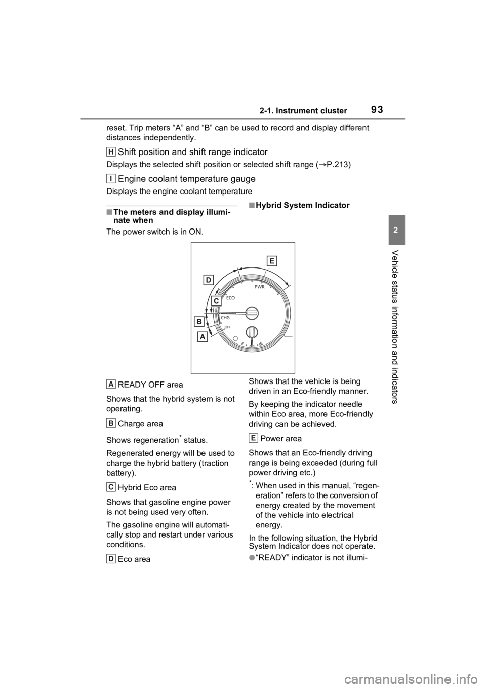
The power swit ch is in ON.■Hybrid System Indicator
READY OFF area
Shows that the hybrid system is not
operating.
Charge area
Shows regeneration
* status.
Regenerated e nergy will be used to
charge the hybrid battery (traction
battery).
Hybrid Eco area
Shows that gasoline engine power
is not being used very often.
The gasoline engine will automati-
cally stop and rest art under various
conditions.
Eco area Shows that the vehicle is being
driven in an Eco-friendly manner.
By keeping the indicator needle
within Eco area, more Eco-friendly
driving can be achieved.
Power area
Shows that an Eco-friendly driving
range is being exceeded (during full
power driving etc.)
*: When used in this manual, “regen- eration” refers to the conversion of
energy created by the movement
of the vehicle into electrical
energy.
In the following situation, the Hybrid
System Indicator does not operate.
●“READY” indicator is not illumi-
H
I
A
B
C
D
E
Page 98 of 752

982-1. Instrument cluster
Trip meter:
Displays the distance the vehicle has been driven since the meter was last
reset. Trip meters “A” and “B” c an be used to record and display different
distances independently.
Outside temperature ( P.99)
Multi-information display
Presents the driver with a variety of driving-related data ( P.101)
Displays warning messages if a malfunction occurs (P.635)
Shift position and shift range indicator
Displays the selected shift posit ion or selected shift range (P.213)
■The meters and display illumi-
nate when
The power swit ch is in ON.■When changing driving mode
Speedometer color is changed fol-
lowing the selected driving mode or
when Trail Mode is turned on.
( P.358, 359)
■Hybrid System Indicator
READY OFF area
Shows that the hybrid system is not
operating.
Charge area
Shows regeneration
* status. Regen-
erated energy will be used to charge
the hybrid battery (traction battery).
Hybrid Eco area
Shows that gasoline engine power is not being used very often.
The gasoline engi
ne will automati-
cally stop and restart under various
conditions.
Eco area
Shows that the vehicle is being
driven in an Eco-friendly manner.
By keeping the indicator needle
within Eco area, more Eco-friendly
driving can be achieved.
G
H
I
A
B
C
D