2022 TOYOTA RAV4 HYBRID engine
[x] Cancel search: enginePage 75 of 752

751-4. Hybrid system
1
For safety and security
*: This function can only be used in
the mainland U.S.A. It cannot be
used in other states and territo-
ries, including Alaska and Hawaii.
This system operates based on
the driving situation and traffic
information to enhance fuel
economy.
For details about Predictive effi-
cient drive, refer to “NAVIGA-
TION AND MULTIMEDIA
SYSTEM OWNER’S MANUAL”.
■Predictive deceleration sup-
port
When the vehicle approaches
to predictive deceleration sup-
port points registered in the
navigation system, the “Refer-
ence operation range” ( ) of
the ECO Accelerator Guid-
ance ( P.103) on the multi-
information display will be
turned off to encourage the
driver to reduce excessive
acceleration.
The engine braking force will be increased according to the
driving conditions to more effi-
ciently charge the hybrid bat-
tery (traction battery) after the
accelerator pedal is released.
■Predictive SOC* control
The following types of control
are performed based on data
such as road and traffic informa-
tion during route guidance by
the navigation system to help
ensure that the vehicle effi-
ciently uses electricity.
When there is a long downhill
slope along the route, the sys-
tem reduces the hybrid bat-
tery (traction battery) level
before reaching the slope to
help ensure charging capacity
for regenerative braking while
traveling downhill.
When traffic congestion is
predicted along the route, the
system helps ensure a certain
battery level before reaching
congested roads to reduce
the frequency of starting the
engine to charge the hybrid
battery (traction battery) due
to low battery levels.
*: SOC means state of charge
Predictive efficient drive
(vehicles with navigation
system)
*
A
Page 88 of 752

882-1. Instrument cluster
*1: These lights turn on when the
power switch is turned to ON to
indicate that a system check is
being performed. They will turn
(Yellow)
Brake system warn-
ing light
*1 ( P.624)
Charging system
warning light
*1
( P.624)
High coolant tempera-
ture warning light
*2
( P.625)
Hybrid system over-
heat warning light
*2
( P.625)
Low engine oil pres-
sure warning light
*2
( P.625)
(U.S.A.)
Malfunction indicator
lamp
*1 ( P.625)
(Canada)
Malfunction indicator
lamp
*1 ( P.625)
SRS warning light
*1
( P.626)
(U.S.A.)
ABS warning light*1
( P.626)
(Canada)
ABS warning light*1
( P.626)
(Red/yellow)
Electric power steer-
ing system warning
light
*1 ( P.626)
(Flashes or
illuminates)
PCS warning light*1
( P.627)
(Orange)
LTA indicator
( P.627)
(Flashes)
Intuitive parking assist
OFF indicator
*3 (if
equipped) ( P.628)
(Flashes)
PKSB OFF indica-
tor
*1 (if equipped)
( P.628)
(Flashes)
RCTA OFF indica-
tor
*1 (if equipped)
( P.629)
Slip indicator light
*1
( P.629)
Inappropriate pedal
operation warning
light
*2 ( P.629)
(Flashes)
Brake hold operated
indicator
*1 ( P.630)
(U.S.A.)
(Flashes)
Parking brake indica-
tor ( P.630)
(Canada)
(Flashes)
Parking brake indica-
tor ( P.630)
Tire pressure warning
light
*1 (if equipped)
( P.630)
Low fuel level warn-
ing light ( P.631)
Driver’s and front pas-
senger’s seat belt
reminder light
( P.631)
Rear passengers’ seat
belt reminder lights (if
equipped) ( P.631)
Page 93 of 752

932-1. Instrument cluster
2
Vehicle status information and indicators
reset. Trip meters “A” and “B” can be used to record and display different
distances independently.
Shift position and shift range indicator
Displays the selected shift posit ion or selected shift range (P.213)
Engine coolant temperature gauge
Displays the engine c oolant temperature
■The meters and display illumi-
nate when
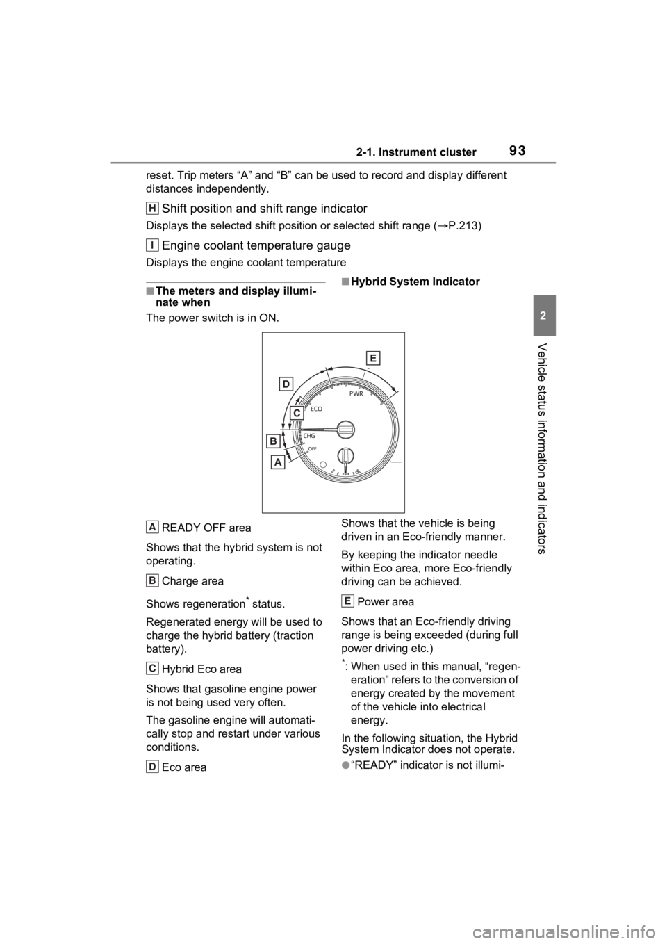
The power swit ch is in ON.■Hybrid System Indicator
READY OFF area
Shows that the hybrid system is not
operating.
Charge area
Shows regeneration
* status.
Regenerated e nergy will be used to
charge the hybrid battery (traction
battery).
Hybrid Eco area
Shows that gasoline engine power
is not being used very often.
The gasoline engine will automati-
cally stop and rest art under various
conditions.
Eco area Shows that the vehicle is being
driven in an Eco-friendly manner.
By keeping the indicator needle
within Eco area, more Eco-friendly
driving can be achieved.
Power area
Shows that an Eco-friendly driving
range is being exceeded (during full
power driving etc.)
*: When used in this manual, “regen- eration” refers to the conversion of
energy created by the movement
of the vehicle into electrical
energy.
In the following situation, the Hybrid
System Indicator does not operate.
●“READY” indicator is not illumi-
H
I
A
B
C
D
E
Page 94 of 752

942-1. Instrument cluster
nated.
●The shift lever is in a range other
than D or S.
■Outside temperature display
●In the following si tuations, the cor-
rect outside tempe rature may not
be displayed, or the display may
take longer than normal to
change.
• When stopped, or driving at low speeds (less than 12 mph [20
km/h])
• When the outside temperature has changed suddenly (at the
entrance/exit of a garage, tunnel,
etc.)
●When “--” or “E” is displayed, the
system may be malfunctioning.
Take your vehicle to your Toyota
dealer.
●Displays the outside temperature
within the range of -40°F (-40°C)
to 122°F (50°C).
●When the outside temperature is
approximately 37°F (3°C) or
lower, the indicator will flash
for approximately 10 seconds,
then stay on.
■Liquid crystal display
P.102
Switches the items of the odom-
eter, trip meter A and trip meter
B by pressing the “ODO TRIP”
switch.
When the trip meter is dis-
played, pressing and holding the
switch will reset the trip meter.
WARNING
■The information display at
low temperatures
Allow the interior of the vehicle to
warm up before using the liquid
crystal information display. At
extremely low temperatures, the
display monitor may respond
slowly, and display changes may
be delayed.
For example, there is a lag
between the driver’s shifting and
the new shift range appearing on
the display. This lag could cause
the driver to downshift again,
causing rapid and excessive
engine braking and possibly an
accident resulting in death or
injury.
NOTICE
■To prevent damage to the
engine and its components
The engine may be overheating if
the engine coolant temperature
gauge is in the red zone (“H”). In
this case, immediately stop the
vehicle in a safe place, and check
the engine after it has cooled
completely. ( P.659)
Using the “ODO TRIP”
switch
Page 96 of 752

962-1. Instrument cluster
The display of the speedometer can be selected from two types,
analog or digital. (P.107)
Analog speedometer
The units used on the meter and display may differ depending on the target
region.
Hybrid System Indicator
Displays the Hybrid System Indicator ( P.98)
Speedometer
Displays the vehicle speed
Clock ( P.100)
Fuel gauge
Displays the quantity of fu el remaining in the tank
Engine coolant temperature gauge
Displays the engine coolant temperature
Odometer and trip meter
Odometer:
Displays the total distance th at the vehicle has been driven
Trip meter:
Gauges and meters (with 7-inch display)
The meters display various drive information.
Meter display
A
B
C
D
E
F
Page 97 of 752

972-1. Instrument cluster
2
Vehicle status information and indicators
Displays the distance the vehicle has been driven since the meter was last
reset. Trip meters “A” and “B” c an be used to record and display different
distances independently.
Outside temperature ( P.99)
Multi-information display
Presents the driver with a variety of driving-related data ( P.101)
Displays warning messages if a malfunction occurs (P.635)
Shift position and shift range indicator
Displays the selected shift posit ion or selected shift range (P.213)
Digital speedometer
The units used on the meter and display may differ depending on the target
region.
Hybrid System Indicator
Displays the Hybrid System Indicator ( P.98)
Speedometer
Displays the vehicle speed
Clock ( P.100)
Fuel gauge
Displays the quantity of fu el remaining in the tank
Engine coolant temperature gauge
Displays the engine coolant temperature
Odometer and trip meter
Odometer:
Displays the total distance th at the vehicle has been driven
G
H
I
A
B
C
D
E
F
Page 98 of 752

982-1. Instrument cluster
Trip meter:
Displays the distance the vehicle has been driven since the meter was last
reset. Trip meters “A” and “B” c an be used to record and display different
distances independently.
Outside temperature ( P.99)
Multi-information display
Presents the driver with a variety of driving-related data ( P.101)
Displays warning messages if a malfunction occurs (P.635)
Shift position and shift range indicator
Displays the selected shift posit ion or selected shift range (P.213)
■The meters and display illumi-
nate when
The power swit ch is in ON.■When changing driving mode
Speedometer color is changed fol-
lowing the selected driving mode or
when Trail Mode is turned on.
( P.358, 359)
■Hybrid System Indicator
READY OFF area
Shows that the hybrid system is not
operating.
Charge area
Shows regeneration
* status. Regen-
erated energy will be used to charge
the hybrid battery (traction battery).
Hybrid Eco area
Shows that gasoline engine power is not being used very often.
The gasoline engi
ne will automati-
cally stop and restart under various
conditions.
Eco area
Shows that the vehicle is being
driven in an Eco-friendly manner.
By keeping the indicator needle
within Eco area, more Eco-friendly
driving can be achieved.
G
H
I
A
B
C
D
Page 99 of 752

992-1. Instrument cluster
2
Vehicle status information and indicators
Power area
Shows that an Eco-friendly driving
range is being exceeded (during full
power driving etc.)
*: When used in this manual, “regen- eration” refers to the conversion of
energy created by the movement
of the vehicle into electrical
energy.
In the following situ ation, the Hybrid
System Indicator does not operate.
●“READY” indicator is not illumi-
nated.
●The shift lever is in a range other
than D or S.
■Outside temperature display
●In the following si tuations, the cor-
rect outside tempe rature may not
be displayed, or the display may
take longer than normal to
change.
• When stopped, or driving at low speeds (less than 12 mph [20
km/h])
• When the outside temperature has changed suddenly (at the
entrance/exit of a garage, tunnel,
etc.)
●When “--” or “E” is displayed, the
system may be malfunctioning.
Take your vehicle to your Toyota
dealer.
●Displays the outside temperature
within the range of -40°F (-40°C)
to 122°F (50°C).
●When the outside temperature is
approximately 37°F (3°C) or
lower, the indicator will flash
for approximately 10 seconds,
then stay on.
■Liquid crystal display
P.102
■Customization
Settings (e. g. meter display) can be changed on the screen of the
multi-informat
ion display. (P.107)
Switches the items of the odom-
eter, trip meter A and trip meter
B by pressing the “ODO TRIP”
switch.
When the trip meter is dis-
played, pressing and holding the
switch will reset the trip meter.
E
WARNING
■The information display at
low temperatures
Allow the interior of the vehicle to
warm up before using the liquid
crystal information display. At
extremely low temperatures, the
display monitor may respond
slowly, and display changes may
be delayed.
For example, there is a lag
between the driver’s shifting and
the new shift range appearing on
the display. This lag could cause
the driver to downshift again,
causing rapid and excessive
engine braking and possibly an
accident resulting in death or
injury.
NOTICE
■To prevent damage to the
engine and its components
The engine may be overheating if
the engine coolant temperature
gauge is in the red zone (“H”). In
this case, immediately stop the
vehicle in a safe place, and check
the engine after it has cooled
completely. ( P.659)
Using the “ODO TRIP”
switch