2022 TOYOTA GR YARIS engine
[x] Cancel search: enginePage 75 of 470

73
1
Owner's Manual_Europe_M52P63_en
1-4. Theft deterrent system
For safety and security
●A person inside the vehicle opens a
door or hood, or unlocks the vehicle.
●The battery is recharged or replaced
when the vehicle is locked. ( P.341)
■Alarm-operated door lock
In the following cases, depending on the situation, the door may automatically lock to prevent improper entry into the
vehicle:
●When a person remaining in the vehi-
cle unlocks the door and the alarm is activated.
●While the alarm is activated, a person remaining in the vehicle unlocks the door.
●When recharging or replacing the bat-tery
■Customization
Some functions can be customized. ( P.359)
■The intrusion sensor detection
The intrusion sensor detects intrud-
ers or movement in the vehicle.
This system is designed to deter
and prevent vehicle theft but does
not guarantee absolute security
against all intrusions.
■Setting the intrusion sensor
The intrusion sensor will be set
automatically when the alarm is set.
( P. 7 2 )
■Canceling the intrusion sensor
If you are leaving pets or other
moving things inside the vehicle,
make sure to disable the intrusion
sensor before setting the alarm, as
they will respond to movement
inside the vehicle.
1 Turn the engine switch to OFF.
2 Press the intrusion sensor can-
cel switch.
Press the switch again to re-enable the intrusion sensor.
Each time the intrusion sensor is can- celed/set, a message will be shown on
NOTICE
■To ensure the system operates correctly
Do not modify or remove the system. If modified or removed, the proper operation of the system cannot be
guaranteed.
Intrusion sensor (if
equipped)
Page 76 of 470

74
Owner's Manual_Europe_M52P63_en
1-4. Theft deterrent system
the multi-information display.
■Canceling and automatic re- enabling of the intrusion sensor
●The alarm will still be set even when the intrusion sensor is canceled.
●After the intrusion sensor is canceled, pressing the engine switch or unlock-ing the doors using the entry function
or wireless remote control will re- enable the intrusion sensor.
●The intrusion sensor will automatically be re-enabled when the alarm system is reactivated.
■Intrusion sensor detection consid-
erations
The sensor may trigger the alarm in the following situations:
●People or pets are in the vehicle.
●A side window is open.
In this case, the sensor may detect the
following:
• Wind or the movement of objects such
as leaves and insects inside the vehi- cle• Ultrasonic waves emitted from
devices such as the intrusion sensors of other vehicles
• The movement of people outside the
vehicle
●Unstable items, such as dangling
accessories or clothes hanging on the coat hooks, are in the vehicle.
●The vehicle is parked in a place where extreme vibrations or noises occur, such as in a parking garage.
●Ice or snow is removed from the vehi-cle, causing the vehicle to receive
repeated impacts or vibrations.
●The vehicle is inside an automatic or
high-pressure car wash.
●The vehicle experiences impacts,
Page 80 of 470

78
Owner's Manual_Europe_M52P63_en
2-1. Instrument cluster
2-1.In strument clu ste r
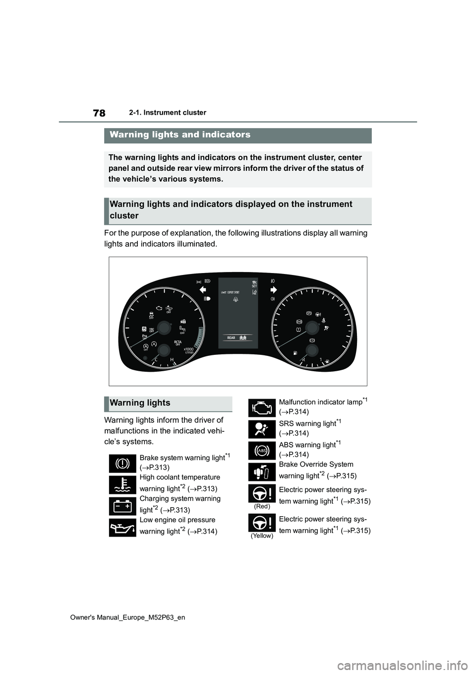
For the purpose of explanation, the following illustrations display all warning
lights and indicators illuminated.
Warning lights inform the driver of
malfunctions in the indicated vehi-
cle’s systems.
Warning lights and indicators
The warning lights and indicators on the instrument cluster, center
panel and outside rear view mirrors inform the driver of the st atus of
the vehicle’s various systems.
Warning lights and indicators displayed on the instrument
cluster
Warning lights
Brake system warning light*1
( P.313)
High coolant temperature
warning light*2 ( P.313)
Charging system warning
light*2 ( P.313)
Low engine oil pressure
warning light*2 ( P.314)
Malfunction indicator lamp*1
( P.314)
SRS warning light*1
( P.314)
ABS warning light*1
( P.314)
Brake Override System
warning light*2 ( P. 3 1 5 )
(Red)
Electric power steering sys-
tem warning light*1 ( P.315)
(Yellow)
Electric power steering sys-
tem warning light*1 ( P.315)
Page 81 of 470

79
2
Owner's Manual_Europe_M52P63_en
2-1. Instrument cluster
Vehicle status information and indicators
*1: These lights come on when the
engine switch is turned to ON to indi-
cate that a system check is being
performed. They will turn off after the
engine is started, or after a few sec-
onds. There may be a malfunction in
a system if the lights do not come
on, or turn off. Have the vehicle
inspected by any authorized Toyota
retailer or Toyota authorized repairer,
or any reliable repairer.
*2: This light illuminates on the multi-
information display.
The indicators inform the driver of
the operating state of the vehicle’s
various systems.
Low fuel level warning light
( P.315)
Driver’s and front passen-
ger’s seat belt reminder light
( P.316)
Rear passengers’ seat
belt reminder lights*2
( P.316)
Tire pressure warning light*1
( P.317)
(Orange)
LTA indicator*2 (if equipped)
( P.317)
(Flashes)
Stop & Start cancel indica-
tor*1 ( P.317)
(Flashes)
Toyota parking assist-sensor
OFF indicator*1 (if equipped)
( P.318)
(Flashes)
“RCTA OFF” indicator*1 (if
equipped) ( P.318)
(Flashes or illuminates)
PCS warning light*1 (if
equipped) ( P.319)
Slip indicator*1 ( P.319)
WARNING
■If a safety system warning light does not come on
Should a safety system light such as the ABS and SRS warning light not come on when you start the engine,
this could mean that these systems are not available to help protect you in an accident, which could result in
death or serious injury. Have the vehi- cle inspected by any authorized Toyota retailer or Toyota authorized
repairer, or any reliable repairer immediately if this occurs.
Indicators
Turn signal indicator
( P.140)
Tail light indicator ( P.142)
Headlight high beam indica-
tor ( P.143)
Automatic High Beam indica-
tor (if equipped) ( P.145)
Front fog light indicator
( P.148)
Rear fog light indicator
( P.148)
PCS warning light*1, 2 (if
equipped) ( P.162)
Cruise control indicator*3 (if
equipped) ( P.179)
Dynamic radar cruise control
indicator*3 (if equipped)
( P.179)
Cruise control “SET” indica-
tor*3 (if equipped) ( P.179)
Page 82 of 470

80
Owner's Manual_Europe_M52P63_en
2-1. Instrument cluster
*1: These lights come on when the
engine switch is turned to ON to indi-
cate that a system check is being
performed. They will turn off after the
engine is started, or after a few sec-
onds. There may be a malfunction in
a system if the lights do not come
on, or turn off. Have the vehicle
inspected by any authorized Toyota
retailer or Toyota authorized repairer,
or any reliable repairer.
*2: This light comes on when the system
is turned off.
*3: This light illuminates on the multi-
information display.
*4: Depending on the operating condi-
tion, the color and illuminating/flash-
ing state of the light change.
*5: This light illuminates on the outside
rear view mirrors.
*6: When the outside temperature is
approximately 3°C (37°F) or lower,
this indicator will flash for approxi-
mately 10 seconds, then stay on.
*7: This light illuminates on the center
panel.
*4
LTA indicator*3 (if equipped)
( P.175)
BSM outside rear view mirror
indicators*1, 5 (if equipped)
( P.199, 210)
BSM OFF indicator*2 (if
equipped) ( P.199)
Toyota parking assist-sensor
OFF indicator*1, 2 (if
equipped) ( P.205)
“RCTA OFF” indicator*1, 2 (if
equipped) ( P. 2 1 1 )
Stop & Start indicator*1
( P.194)
Stop & Start cancel indica-
tor*1, 2 ( P.194)
(Flashes)
Slip indicator*1 (P.218)
“TRC OFF” indicator*2
( P.218)
VSC OFF indicator*1, 2
( P.218)
Smart entry & start system
indicator*3 ( P.134)
Gear Shift Indicator
( P.139)
Parking brake indicator
( P.141)
Low outside temperature
indicator*3, 6 ( P. 8 1 )
Security indicator ( P. 7 0 ,
72)
“PASSENGER AIR
BAG” indicator*1, 7
( P.43)
“iMT” indicator*3 ( P.138)
Sport mode indicator*3
( P.215)
Track mode indicator*3
( P.215)
Expert mode indicator*3
( P.219)
Page 83 of 470

81
2
Owner's Manual_Europe_M52P63_en
2-1. Instrument cluster
Vehicle status information and indicators
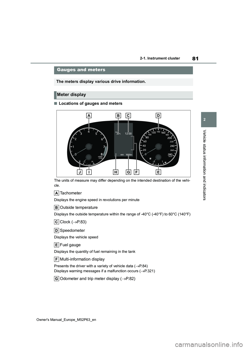
■Locations of gauges and meters
The units of measure may differ depending on the intended destination of the vehi-
cle.
Tachometer
Displays the engine speed in revolutions per minute
Outside temperature
Displays the outside temperature within the range of -40°C (-40 °F) to 60°C (140°F)
Clock (P.83)
Speedometer
Displays the vehicle speed
Fuel gauge
Displays the quantity of fuel remaining in the tank
Multi-information display
Presents the driver with a variety of vehicle data ( P. 8 4 )
Displays warning messages if a malfunction occurs ( P.321)
Odometer and trip meter display (P. 8 2 )
Gauges and meters
The meters display various drive information.
Meter display
Page 84 of 470

82
Owner's Manual_Europe_M52P63_en
2-1. Instrument cluster
Gear Shift Indicator (P.139)
Engine coolant temperature gauge
Displays the engine coolant temperature
Display change button ( P. 8 2 )
■Outside temperature display
●In the following situations, the correct
outside temperature may not be dis- played, or the display may take longer than normal to change:
• When stopped, or driving at low speeds (less than 25 km/h [16 mph])• When the outside temperature has
changed suddenly (at the entrance/exit of a garage, tunnel, etc.)
●When “--” is displayed, the system may be malfunctioning. Take your
vehicle to any authorized Toyota retailer or Toyota authorized repairer, or any reliable repairer.
■Liquid crystal display
P. 8 5
■Customization
The gauges and meters can be custom-
ized in of the multi-information dis-
play. ( P.359)
■Changing the display
Press the display change button
until the desired item is displayed.
WARNING
■The information display at low temperatures
Allow the interior of the vehicle to
warm up before using the liquid crys- tal information display. At extremely low temperatures, the information dis-
play monitor may respond slowly, and display changes may be delayed.
For example, there is a lag between
the driver’s shifting and the new gear number appearing on the display. This lag could cause the driver to
downshift again, causing rapid and excessive engine braking and possi-bly an accident resulting in death or
injury.
NOTICE
■To prevent damage to the engine and its components
●Do not let the indicator needle of the tachometer enter the red zone, which indicates the maximum
engine speed.
●The engine may be overheating if
the engine coolant temperature gauge is in the red zone (H). In this case, immediately stop the vehicle
in a safe place, and check the engine after it has cooled com-pletely. ( P.344)
Odometer and trip meter
display
Page 88 of 470

86
Owner's Manual_Europe_M52P63_en
2-1. Instrument cluster
multimedia system Owner’s manual”.
■Display items
Speedometer display/Driving
range
Fuel economy
■Speedometer display/Driving
range
Speedometer display
Driving range
Displays driving range with remaining
fuel. Use the displayed values as a ref-
erence only.
This distance is computed based on
your average fuel consumption. As a
result, the actual distance that can be
driven may differ from that displayed.
When only a small amount of fuel is
added to the tank, the display may not
be updated.
When refueling, turn the engine switch
off. If the vehicle is refueled without
turning the engine switch off, the dis-
play may not be updated.
■Fuel economy
Use the displayed values as a refer-
ence only.
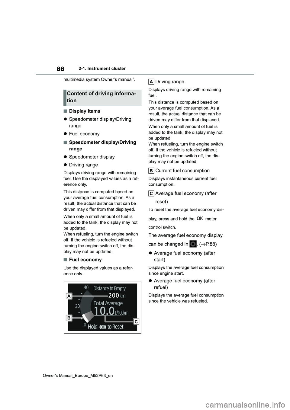
Driving range
Displays driving range with remaining
fuel.
This distance is computed based on
your average fuel consumption. As a
result, the actual distance that can be
driven may differ from that displayed.
When only a small amount of fuel is
added to the tank, the display may not
be updated.
When refueling, turn the engine switch
off. If the vehicle is refueled without
turning the engine switch off, the dis-
play may not be updated.
Current fuel consumption
Displays instantaneous current fuel
consumption.
Average fuel economy (after
reset)
To reset the average fuel economy dis-
play, press and hold the meter
control switch.
The average fuel economy display
can be changed in . ( P. 8 8 )
Average fuel economy (after
start)
Displays the average fuel consumption
since engine start.
Average fuel economy (after
refuel)
Displays the average fuel consumption
since the vehicle was refueled.
Content of driving informa-
tion