Page 13 of 132
8Cruise Control or Advanced Adaptive Cruise Control (p. 15)
9Multi-Function Display (MFD) (p. 16)
10Windshield Wipers (p. 19)
11STARLINK
®Multimedia Touchscreen (p. 49)
12Climate Control System (p. 26)
13Shifter (MT) or CVT Select Lever (p. 31)
14Parking Brake
INSTRUMENT PANEL
11
Page 15 of 132
WARNING AND INDICATOR LIGHTS
Redlights indicate immediate attention is required. Some examples are:
Seatbelt warning Door open Brake system
Yellowlights indicate caution. Some examples are:
Low fuelEngine low oil level
warning lightTire pressure warning light
Greenandbluelights are for information. Some examples are:
Headlight indicator light Cold coolant temperatureHigh beam
indicator light
GAUGES AND WARNING LIGHTS
13
Page 20 of 132

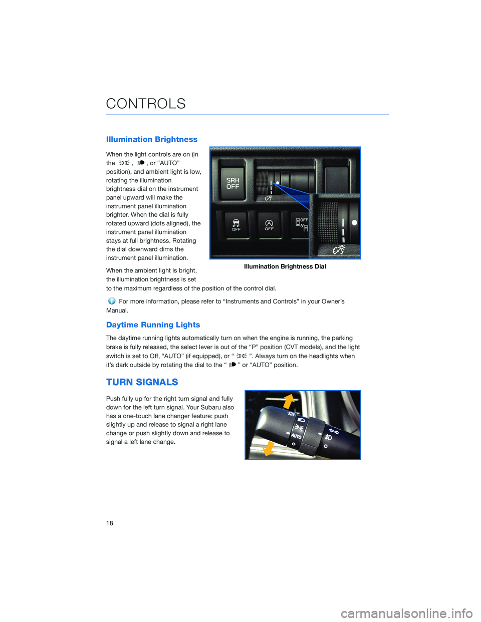
Illumination Brightness
When the light controls are on (in
the
,, or “AUTO”
position), and ambient light is low,
rotating the illumination
brightness dial on the instrument
panel upward will make the
instrument panel illumination
brighter. When the dial is fully
rotated upward (dots aligned), the
instrument panel illumination
stays at full brightness. Rotating
the dial downward dims the
instrument panel illumination.
When the ambient light is bright,
the illumination brightness is set
to the maximum regardless of the position of the control dial.
For more information, please refer to “Instruments and Controls” in your Owner’s
Manual.
Daytime Running Lights
The daytime running lights automatically turn on when the engine is running, the parking
brake is fully released, the select lever is out of the “P” position (CVT models), and the light
switch is set to Off, “AUTO” (if equipped), or “
”. Always turn on the headlights when
it’s dark outside by rotating the dial to the “
” or “AUTO” position.
TURN SIGNALS
Push fully up for the right turn signal and fully
down for the left turn signal. Your Subaru also
has a one-touch lane changer feature: push
slightly up and release to signal a right lane
change or push slightly down and release to
signal a left lane change.
Illumination Brightness Dial
CONTROLS
18
Page 32 of 132

IGNITION SWITCH
The ignition switch has four positions:
LOCK:You can only insert or remove the key in this position.
ACC (Accessory):Provides power to the audio system and accessory power outlets.
ON:All electrical systems are available. The key returns to this position after starting the
engine.
START:Turn the key to this position to start the engine.
PUSH-BUTTON IGNITION SWITCH(if equipped)
Each time you press the ignition switch without
depressing the brake pedal (or clutch pedal for manual
transmission vehicles), the ignition position will change
as follows: ACC, ON, OFF.
ACC (Accessory):Provides power to the audio
system and accessory power outlets. Orange indicator
illuminates.
ON:All electrical systems are available. Orange indicator illuminates.
OFF:Power off and indicator off.
STARTING THE VEHICLE
Without Push-button Ignition
To start the engine:
1. Make sure the select lever is in the “P” position (or neutral position and depress the
clutch for manual transmission vehicles).
2. Using the key, turn the ignition switch to “START”.
NOTE: Do not depress the accelerator pedal. Release the key as soon as the engine
starts.
With Push-button Ignition
To start the engine:
1. Sit in the driver’s seat with the access key fob.
2.
Make sure the select lever is in the “P” position or neutral for manual transmission vehicles.
3. Depress the brake pedal (and clutch pedal for manual transmission vehicles).
4. When the Engine START/STOP button indicator turns green, briefly press and release
the Engine START/STOP button.
OPERATING THE VEHICLE
30
Page 36 of 132

System Operation
So that it can be used safely and comfortably, the Auto Start-Stop system is designed to
constantly monitor vehicle conditions, the environment inside and outside the vehicle, as
well as driver operations, in order to control stopping and restarting the engine.
After the vehicle has been completely stopped by depressing the brake pedal
with the select lever in the “D” position, the engine will be automatically
stopped and the green indicator will illuminate in the combination meter.
If you release the brake pedal with the select lever kept in the “D” position, the
engine will be automatically restarted. The indicator light will turn off when the system
restarts the engine.
There are several operating conditions for this system to operate as intended.
For more information, please refer to “Starting and Operating” in your Owner’s
Manual.
Auto Start-Stop Screen
You can use the “i/Set” and arrow switches to
display the Auto Start-Stop Screen in the
Combination Meter Display (CMD), showing
how much time the engine was off in the top
line and the amount of fuel saved in the
bottom line. Displayed are the total stop time
and fuel saved since the trip meter was reset.
No Activity Detected Indicator Light
If the operational conditions are not met when the vehicle is stopped, the
engine will not stop and the white Auto Start-Stop No Activity Detected
indicator light will illuminate. It will turn off when the brake pedal is released.
Auto Start-Stop Warning Light
The Auto Start-Stop warning light will illuminate in yellow when initially turning
the ignition switch to the “ON” position. The light will turn off after the engine
has started.
NOTE: If the Auto Start-Stop warning light does not turn off after the engine
has started or is flashing, the Auto Start-Stop system may be malfunctioning. We
recommend that you contact your authorized SUBARU retailer for an inspection.
OPERATING THE VEHICLE
34
Page 37 of 132

INDICATOR PATTERN CONDITION
Solid green This indicator light illuminates when the engine has been
temporarily stopped by the Auto Start-Stop system. It
will turn off when the engine is restarted.
Solid White Operational conditions have not been met, the engine
will not stop and this light will illuminate. The light turns
off once the brake pedal is released.
Solid Yellow This light indicates that the system has been turned off.
The light will turn off once the system is turned back on.
Flashing
YellowA fault has been detected with the Start-Stop system.
Please contact your authorized Subaru Retailer.
X-MODE®(if equipped)
X-MODE®is the integrated control system of the
engine, All Wheel Drive, and Vehicle Dynamics Control
(VDC) systems for driving with bad road conditions.
Using X-MODE
®, you can drive more comfortably
even in slippery road conditions, such as mud or
snow, including uphill and
downhill. You can activate the
system when the vehicle speed is
less than 12 mph. If the vehicle
speed reaches 25 mph, the
X-MODE
®system is canceled and
can be reactivated once the once
the vehicle speed is lower.
X-MODE®Multi-Function
Display
X-MODE®Switch
OPERATING THE VEHICLE
35
Page 39 of 132

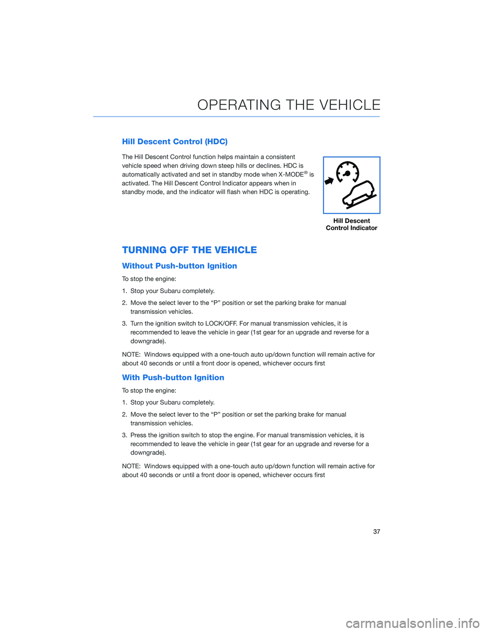
Hill Descent Control (HDC)
The Hill Descent Control function helps maintain a consistent
vehicle speed when driving down steep hills or declines. HDC is
automatically activated and set in standby mode when X-MODE
®is
activated. The Hill Descent Control Indicator appears when in
standby mode, and the indicator will flash when HDC is operating.
TURNING OFF THE VEHICLE
Without Push-button Ignition
To stop the engine:
1. Stop your Subaru completely.
2. Move the select lever to the “P” position or set the parking brake for manual
transmission vehicles.
3. Turn the ignition switch to LOCK/OFF. For manual transmission vehicles, it is
recommended to leave the vehicle in gear (1st gear for an upgrade and reverse for a
downgrade).
NOTE: Windows equipped with a one-touch auto up/down function will remain active for
about 40 seconds or until a front door is opened, whichever occurs first
With Push-button Ignition
To stop the engine:
1. Stop your Subaru completely.
2. Move the select lever to the “P” position or set the parking brake for manual
transmission vehicles.
3. Press the ignition switch to stop the engine. For manual transmission vehicles, it is
recommended to leave the vehicle in gear (1st gear for an upgrade and reverse for a
downgrade).
NOTE: Windows equipped with a one-touch auto up/down function will remain active for
about 40 seconds or until a front door is opened, whichever occurs first
Hill Descent
Control Indicator
OPERATING THE VEHICLE
37
Page 46 of 132
2.0L OR 2.5L ENGINE
1Brake Fluid Reservoir/Clutch Fluid
Reservoir (MT models)
2Fuse Box
3Battery
4Windshield Washer Tank
5Radiator Cap6Engine Oil Filler Cap
7Engine Coolant Reservoir
8Engine Oil Filter
9Engine Oil Dipstick
10Air Cleaner Element
The following table lists recommended first service items. Your maintenance needs
may vary depending on your driving conditions. Please consult with your retailer and refer
to the Warranty and Maintenance Booklet for complete information and recommended
replacement intervals.
Maintenance ItemMaintenance Interval
6 months
or
6,000 Miles12 months
or
12,000 Miles
Replace Engine Oil and Filter • •
Rotate and Inspect Tires • •
Replace HVAC System A/C filter •
Inspect Clutch Operation (Manual
Transmission)•
Inspect Brake System, Steering
System, and Suspension Components•
ENGINE COMPARTMENT
44