2022 RAM PROMASTER check oil
[x] Cancel search: check oilPage 7 of 268
5
SAFETY TIPS ........................................................ 172 Transporting Passengers .............................. 172Transporting Pets ......................................... 173
Connected Vehicles....................................... 173
Safety Checks You Should Make Inside
The Vehicle ................................................... 173Periodic Safety Checks You Should Make
Outside The Vehicle ...................................... 174Exhaust Gas ................................................... 175Carbon Monoxide Warnings ......................... 175
IN CASE OF EMERGENCY
HAZARD WARNING FLASHERS ......................... 176
SOS AND ASSIST SYSTEM ................................. 176
JACKING AND TIRE CHANGING.......................... 180
Preparations For Jacking .............................. 180Jack Location — If Equipped ......................... 181Spare Tire Removal ....................................... 182
Jacking Instructions ...................................... 184Wheel Covers ................................................. 187
TIRE SERVICE KIT — IF EQUIPPED ..................... 187
Tire Service Kit Storage ................................ 187
Tire Service Kit Components And
Operation ....................................................... 187
Tire Service Kit Usage Precautions .............. 188
Sealing A Tire With Tire Service Kit .............. 189
JUMP STARTING................................................... 192
Preparations For Jump Start......................... 192Jump Starting Procedure .............................. 193Battery Location ............................................ 194 IF YOUR ENGINE OVERHEATS .......................... 194
GEAR SELECTOR OVERRIDE ............................. 195
FREEING A STUCK VEHICLE .............................. 196
TOWING A DISABLED VEHICLE ......................... 196 Automatic Transmission ............................... 197
ENHANCED ACCIDENT RESPONSE
SYSTEM (EARS) ................................................... 197
EVENT DATA RECORDER (EDR) ........................ 197
SERVICING AND MAINTENANCE
SCHEDULED SERVICING ................................... 198
Maintenance Plan ......................................... 199
ENGINE COMPARTMENT .................................... 202
3.6L Engine .................................................. 202
Checking Oil Level ......................................... 203
Adding Washer Fluid ..................................... 203
Maintenance-Free Battery ........................... 204Pressure Washing ......................................... 204
VEHICLE MAINTENANCE..................................... 204
Engine Oil ....................................................... 205
Engine Oil Filter ............................................. 205Engine Air Cleaner Filter .............................. 205Air Conditioner Maintenance ....................... 206
Body Lubrication ........................................... 207Windshield Wiper Blades ............................. 207
Exhaust System ............................................ 208
Cooling System .............................................. 209
Brake System ............................................... 211
Automatic Transmission ............................... 212 Fuses.............................................................. 213
Bulb Replacement ....................................... 220
TIRES .................................................................... 225
Tire Safety Information ................................ 225Tires — General Information ......................... 233
Tire Types....................................................... 236Spare Tires — If Equipped ............................ 237
Wheel And Wheel Trim Care ........................ 239Snow Traction Devices ................................. 240
Tire Rotation Recommendations ................. 241
DEPARTMENT OF TRANSPORTATION UNIFORM
TIRE QUALITY GRADES ...................................... 242
Treadwear...................................................... 242
Traction Grades ............................................. 242Temperature Grades..................................... 242
STORING THE VEHICLE ...................................... 243
BODYWORK .......................................................... 243
Protection From Atmospheric Agents .......... 243
Body And Underbody Maintenance ............. 243
Preserving The Bodywork ............................. 244
INTERIORS ........................................................... 244
Seats And Fabric Parts ................................. 244
Plastic And Coated Parts .............................. 245
Leather Surfaces........................................... 245
Glass Surfaces ............................................. 246Cleaning The Instrument Panel
Cupholders .................................................... 246
22_VF_OM_EN_USC_t.book Page 5
Page 54 of 268
52GETTING TO KNOW YOUR INSTRUMENT PANEL
BASE / MIDLINE INSTRUMENT CLUSTER
D
ESCRIPTIONS
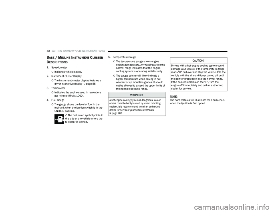
1. Speedometer
Indicates vehicle speed.
2. Instrument Cluster Display
The instrument cluster display features a
driver interactive display Ú page 55.
3. Tachometer
Indicates the engine speed in revolutions
per minute (RPM x 1000).
4. Fuel Gauge
The gauge shows the level of fuel in the
fuel tank when the ignition switch is in the
ON/RUN position.
The fuel pump symbol points to
the side of the vehicle where the
fuel door is located. 5. Temperature Gauge
The temperature gauge shows engine
coolant temperature. Any reading within the
normal range indicates that the engine
cooling system is operating satisfactorily.
The gauge pointer will likely indicate a
higher temperature when driving in hot
weather or up mountain grades. It should
not be allowed to exceed the upper limits of
the normal operating range.
NOTE:The hard telltales will illuminate for a bulb check
when the ignition is first cycled.
WARNING!
A hot engine cooling system is dangerous. You or
others could be badly burned by steam or boiling
coolant. It is recommended to call an authorized
dealer for service if your vehicle overheats
Ú
page 209.
CAUTION!
Driving with a hot engine cooling system could
damage your vehicle. If the temperature gauge
reads “H” pull over and stop the vehicle. Idle the
vehicle with the air conditioner turned off until
the pointer drops back into the normal range.
If the pointer remains on the “H”, turn the
engine off immediately and call an authorized
dealer for service.
22_VF_OM_EN_USC_t.book Page 52
Page 63 of 268
GETTING TO KNOW YOUR INSTRUMENT PANEL61
Rear Cargo Door Open Warning Light -
If Equipped
This warning light will illuminate when the
rear cargo door is open.
NOTE:This light will flash at a fast rate for approximately
15 seconds when the vehicle security system is
arming, and then will flash slowly until the vehicle
is disarmed.
Oil Pressure Warning Light
This warning light will illuminate to
indicate low engine oil pressure. If the
light turns on while driving, stop the
vehicle, shut off the engine as soon
as possible, and contact an authorized dealer.
A chime will sound when this light turns on.
Do not operate the vehicle until the cause is
corrected. This light does not indicate how much oil
is in the engine. The engine oil level must be
checked under the hood.
Seat Belt Reminder Warning Light
When the ignition is first placed in the
ON/RUN or MAR/ON/RUN position, if the
driver’s seat belt is unbuckled, a chime
will sound and the light will turn on. When
driving, if the driver or front passenger seat belt
remains unbuckled, the Seat Belt Reminder Light
will flash or remain on continuously and a chime
will sound Ú page 154.
Transmission Fault Warning Light
This light will illuminate (together with a
message in the instrument cluster display
and a buzzer) to indicate a transmission
fault. Contact an authorized dealer if the
message remains after restarting the engine.
Vehicle Security Warning Light —
If Equipped
This light will flash at a fast rate for
approximately 15 seconds when the vehicle
security system is arming, and then will flash
slowly until the vehicle is disarmed.
YELLOW WARNING LIGHTS
Adaptive Cruise Control (ACC) Fault
Warning Light — If Equipped
This warning light will illuminate to
indicate a fault in the ACC system.
Contact a local authorized dealer for
service Ú page 82.
Anti-Lock Brake System (ABS) Warning
Light
This light monitors the ABS. The light will
turn on when the ignition is placed in the
ON/RUN or MAR/ON/RUN position and
may stay on for as long as four seconds.
If the ABS light remains on or turns on while
driving, then the Anti-Lock portion of the brake
system is not functioning and service is required.
However, the conventional brake system will
continue to operate normally if the brake warning
light is not on.
If the ABS light is on, the brake system should be
serviced as soon as possible to restore the
benefits of Anti-Lock Brakes. If the ABS light
does not turn on when the ignition is placed in the
ON/RUN or MAR/ON/RUN position, have the light
inspected by an authorized dealer.
3
22_VF_OM_EN_USC_t.book Page 61
Page 73 of 268
STARTING AND OPERATING71
NOTE:A new engine may consume some oil during its first
few thousand miles (kilometers) of operation. This
should be considered a normal part of the break-in
and not interpreted as a problem. Please check
your oil level with the engine oil indicator often
during the break-in period. Add oil as required.
PARKING BRAKE
ELECTRIC PARK BRAKE (EPB)
Your vehicle is equipped with an EPB that offers
simple operation, and some additional features
that make the parking brake more convenient and
useful.
The parking brake is primarily intended to prevent
the vehicle from rolling while parked. Before
leaving the vehicle, make sure that the parking
brake is applied. Also, be certain to leave the
transmission in PARK.
You can engage the parking brake in two ways:
Manually, by applying the parking brake switch.
Automatically, by enabling the Auto Park Brake
feature in the Customer Programmable
Features section of the Uconnect settings.
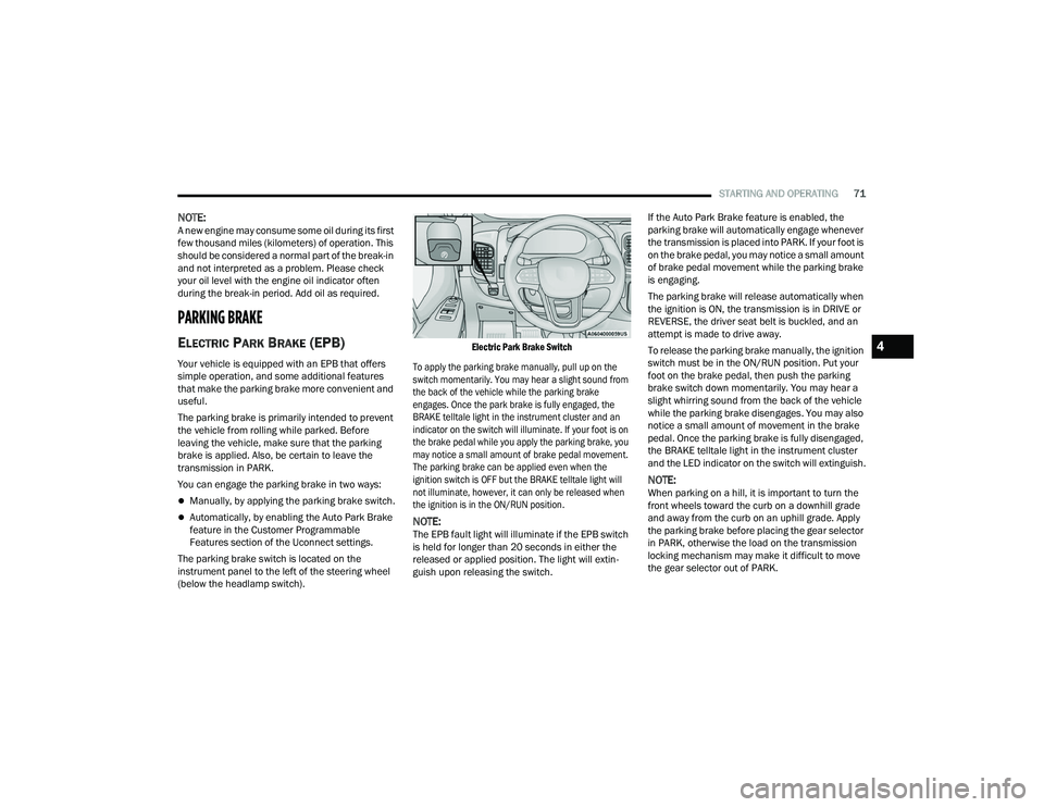
The parking brake switch is located on the
instrument panel to the left of the steering wheel
(below the headlamp switch).
Electric Park Brake Switch
To apply the parking brake manually, pull up on the
switch momentarily. You may hear a slight sound from
the back of the vehicle while the parking brake
engages. Once the park brake is fully engaged, the
BRAKE telltale light in the instrument cluster and an
indicator on the switch will illuminate. If your foot is on
the brake pedal while you apply the parking brake, you
may notice a small amount of brake pedal movement.
The parking brake can be applied even when the
ignition switch is OFF but the BRAKE telltale light will
not illuminate, however, it can only be released when
the ignition is in the ON/RUN position.
NOTE:The EPB fault light will illuminate if the EPB switch
is held for longer than 20 seconds in either the
released or applied position. The light will extin -
guish upon releasing the switch. If the Auto Park Brake feature is enabled, the
parking brake will automatically engage whenever
the transmission is placed into PARK. If your foot is
on the brake pedal, you may notice a small amount
of brake pedal movement while the parking brake
is engaging.
The parking brake will release automatically when
the ignition is ON, the transmission is in DRIVE or
REVERSE, the driver seat belt is buckled, and an
attempt is made to drive away.
To release the parking brake manually, the ignition
switch must be in the ON/RUN position. Put your
foot on the brake pedal, then push the parking
brake switch down momentarily. You may hear a
slight whirring sound from the back of the vehicle
while the parking brake disengages. You may also
notice a small amount of movement in the brake
pedal. Once the parking brake is fully disengaged,
the BRAKE telltale light in the instrument cluster
and the LED indicator on the switch will extinguish.
NOTE:When parking on a hill, it is important to turn the
front wheels toward the curb on a downhill grade
and away from the curb on an uphill grade. Apply
the parking brake before placing the gear selector
in PARK, otherwise the load on the transmission
locking mechanism may make it difficult to move
the gear selector out of PARK.
4
22_VF_OM_EN_USC_t.book Page 71
Page 120 of 268

118STARTING AND OPERATING
(Continued)
DRIVING THROUGH WATER
Driving through water more than a few inches/
centimeters deep will require extra caution to
ensure safety and prevent damage to your vehicle.
Flowing/Rising Water
Shallow Standing Water
Although your vehicle is capable of driving through
shallow standing water, consider the following
Cautions and Warnings before doing so.
WARNING!
Do not drive on or across a road or path where
water is flowing and/or rising (as in storm
run-off). Flowing water can wear away the road
or path's surface and cause your vehicle to sink
into deeper water. Furthermore, flowing and/or
rising water can carry your vehicle away swiftly.
Failure to follow this warning may result in
injuries that are serious or fatal to you, your
passengers, and others around you.
WARNING!
Driving through standing water limits your
vehicle’s traction capabilities. Do not exceed
5 mph (8 km/h) when driving through
standing water.
Driving through standing water limits your
vehicle’s braking capabilities, which increases
stopping distances. Therefore, after driving
through standing water, drive slowly and
lightly press on the brake pedal several times
to dry the brakes.
Failure to follow these warnings may result in
injuries that are serious or fatal to you, your
passengers, and others around you.
CAUTION!
Always check the depth of the standing water
before driving through it. Never drive through
standing water that is deeper than the bottom
of the tire rims mounted on the vehicle.
Determine the condition of the road or the
path that is under water and if there are any
obstacles in the way before driving through
the standing water.
Do not exceed 5 mph (8 km/h) when driving through standing water. This will minimize
wave effects.
Driving through standing water may cause
damage to your vehicle’s drivetrain compo -
nents. Always inspect your vehicle’s fluids
(i.e., engine oil, transmission, axle, etc.) for
signs of contamination (i.e., fluid that is milky
or foamy in appearance) after driving through
standing water. Do not continue to operate
the vehicle if any fluid appears contaminated,
as this may result in further damage. Such
damage is not covered by the New Vehicle
Limited Warranty.
Getting water inside your vehicle’s engine can
cause it to lock up and stall out, and cause
serious internal damage to the engine. Such
damage is not covered by the New Vehicle
Limited Warranty.
CAUTION!
22_VF_OM_EN_USC_t.book Page 118
Page 176 of 268
174SAFETY
(Continued)
PERIODIC SAFETY CHECKS YOU SHOULD
M
AKE OUTSIDE THE VEHICLE
Tires
Examine tires for excessive tread wear and uneven
wear patterns. Check for stones, nails, glass, or
other objects lodged in the tread or sidewall.
Inspect the tread for cuts and cracks. Inspect
sidewalls for cuts, cracks, and bulges. Check the
lug nut/bolt torque for tightness. Check the tires
(including spare) for proper cold inflation pressure.
Lights
Have someone observe the operation of brake
lights and exterior lights while you work the
controls. Check turn signal and high beam
indicator lights on the instrument panel.
Door Latches
Check for proper closing, latching, and locking.
Fluid Leaks
Check area under the vehicle after overnight
parking for fuel, coolant, oil, or other fluid leaks.
Also, if gasoline fumes are detected or if fuel or
brake fluid leaks are suspected, the cause should
be located and corrected immediately.
ALWAYS REMOVE THE EXISTING
FLOOR MAT FROM THE VEHICLE
before installing any other floor mat.
NEVER install or stack an additional
floor mat on top of an existing floor mat.
ONLY install floor mats designed to fit your vehicle.
NEVER install a floor mat that cannot be properly
attached and secured to your vehicle. If a floor mat
needs to be replaced, only use a FCA approved
floor mat for the specific make, model, and year of
your vehicle.
ONLY use the driver’s side floor mat on the driver’s
side floor area. To check for interference, with the
vehicle properly parked with the engine off, fully
depress the accelerator, the brake, and the clutch
pedal (if present) to check for interference. If your
floor mat interferes with the operation of any
pedal, or is not secure to the floor, remove the
floor mat from the vehicle and place the floor mat
in your trunk.
ONLY use the passenger’s side floor mat on
the passenger’s side floor area.
WARNING!
ALWAYS make sure objects cannot fall or slide into
the driver’s side floor area when the vehicle is
moving. Objects can become trapped under accel -
erator, brake, or clutch pedals and could cause a
loss of vehicle control.
NEVER place any objects under the floor mat
(e.g., towels, keys, etc.). These objects could
change the position of the floor mat and may
cause interference with the accelerator,
brake, or clutch pedals.
If the vehicle carpet has been removed and
re-installed, always properly attach carpet to
the floor and check the floor mat fasteners are
secure to the vehicle carpet. Fully depress
each pedal to check for interference with the
accelerator, brake, or clutch pedals then
re-install the floor mats.
It is recommended to only use mild soap and
water to clean your floor mats. After cleaning,
always check your floor mat has been properly
installed and is secured to your vehicle using
the floor mat fasteners by lightly pulling mat.
WARNING!
22_VF_OM_EN_USC_t.book Page 174
Page 193 of 268

IN CASE OF EMERGENCY191
(D) Drive Vehicle:
Immediately after injecting sealant and inflating the
tire, drive the vehicle 5 miles (8 km) or 10 minutes to
ensure distribution of the Tire Service Kit Sealant within
the tire. Do not exceed 50 mph (80 km/h).
(E) After Driving:
Pull over to a safe location Ú page 189.
1. Push in the Mode Select Knob (2) and turn to the Air Mode position.
2. Uncoil the power plug and insert the plug into the vehicle's 12 Volt power outlet.
3. Uncoil the Air Pump Hose (5) (black in color) and screw the fitting at the end of hose onto
the valve stem.
4. Check the pressure in the tire by reading the Pressure Gauge (8). If tire pressure is less than 19 psi (1.3 Bar):
The tire is too badly damaged. Do not attempt to
drive the vehicle further. Call for assistance.
If the tire pressure is 19 psi (1.3 Bar) or higher:
1. Push the Power Button (1) to turn on Tire
Service Kit and inflate the tire to the pressure
indicated on the tire and loading information
label on the driver-side door opening.
NOTE:If the tire becomes overinflated, push the Deflation
Button to reduce the tire pressure to the recom -
mended inflation pressure before continuing.
2. Disconnect the Tire Service Kit from the valve stem, reinstall the cap on the valve stem and
unplug from 12 Volt outlet.
3. Place the Tire Service Kit in its proper storage area in the vehicle.
4. Have the tire inspected and repaired or replaced at the earliest opportunity at an
authorized dealer or tire service center.
5. Remove the Speed Limit sticker from the instrument panel after the tire has been
repaired.
6. Replace the Sealant Bottle (4) and Sealant Hose (3) assembly at an authorized dealer as
soon as possible Ú page 191.
NOTE:When having the tire serviced, advise the autho -
rized dealer or service center that the tire has been
sealed using the Tire Service Kit.
(F) Sealant Bottle And Hose Replacement:
1. Uncoil the Sealant Hose (3) (clear in color).
2. Locate the red colored round Sealant Bottle release button at the lower right hand corner
of the kit.
3. Push and hold the Sealant Bottle release button, then pull out the bottle holding the
button.
4. Clean any remaining sealant from the Tire Service Kit housing.
5. Position the new Sealant Bottle (4) in the housing so that the Sealant Hose (3) aligns
with the hose slot in the front of the housing.
Push and hold the Sealant Bottle release
button, then push the bottle into the housing
by holding the button. An audible click will be
heard indicating the bottle is locked into place.
Release the button.
6. Verify that the cap is installed on the fitting at the end of the Sealant Hose (3) and return the
hose to its storage area (located on top of the
housing).
7. Return the Tire Service Kit to its storage location in the vehicle.WARNING!
Tire Service Kit is not a permanent flat tire repair.
Have the tire inspected and repaired or replaced
after using Tire Service Kit. Do not exceed 50 mph
(80 km/h) until the tire is repaired or replaced.
Failure to follow this warning can result in injuries
that are serious or fatal to you, your passengers, and
others around you.
7
22_VF_OM_EN_USC_t.book Page 191
Page 200 of 268
198
SERVICING AND MAINTENANCE
SCHEDULED SERVICING
Your vehicle is equipped with an automatic oil
change indicator system. The oil change indicator
system will remind you that it is time to take your
vehicle in for scheduled maintenance.
Based on engine operation conditions, the oil
change indicator message will illuminate in the
instrument cluster. This means that service is
required for your vehicle. Operating conditions such
as frequent short-trips, trailer tow, and extremely hot
or cold ambient temperatures will influence when
the “Oil Change Required” message is displayed.
Have the vehicle serviced as soon as possible, within
the next 500 miles (805 km).
An authorized dealer will reset the oil change
indicator message after completing the scheduled
oil change. If a scheduled oil change is performed
by someone other than an authorized dealer, the
message can be reset by referring to the steps
described under Instrument Cluster Display
Ú
page 56.
NOTE:Under no circumstances should oil change
intervals exceed 10,000 miles (16,000 km),
12 months or 350 hours of engine run time,
whichever comes first. The 350 hours of engine
run or idle time is generally only a concern for fleet
customers. Once A Month Or Before A Long Trip:
Check engine oil level
Check windshield washer fluid level
Check the tire pressures and look for unusual
wear or damage. Rotate at the first sign of irreg
-
ular wear, even if it occurs before the oil indi -
cator system turns on
Check the fluid levels of the coolant reservoir,
and brake master cylinder and fill as needed
Check function of all interior and exterior lights
22_VF_OM_EN_USC_t.book Page 198