2022 RAM PROMASTER CITY steering
[x] Cancel search: steeringPage 42 of 260
40GETTING TO KNOW YOUR INSTRUMENT PANEL
INSTRUMENT CLUSTER DESCRIPTIONS
1. Speedometer
Indicates vehicle speed.
2. Fuel Gauge
The pointer shows the level of fuel in the
fuel tank when the ignition switch is in the
ON/RUN position.
The fuel pump arrow symbol
points to the side of the vehicle
where the fuel door is located.
3.Temperature Gauge
The temperature gauge shows engine
coolant temperature. Any reading within the
normal range indicates that the engine
cooling system is operating satisfactorily.
The pointer will likely indicate a higher
temperature when driving in hot weather or
up mountain grades. It should not be
allowed to exceed the upper limits of the
normal operating range. 4. Tachometer
Indicates the engine speed in revolutions
per minute (RPM x 1000).
5. Instrument Cluster Display
When the appropriate conditions exist, this
display shows the instrument cluster
display messages Ú page 40.
INSTRUMENT CLUSTER DISPLAY
Your vehicle will be equipped with an instrument
cluster display, which offers useful information to
the driver. With the ignition in the OFF mode,
opening/closing of a door will activate the display
for viewing, and display the total miles, or
kilometers, in the odometer. The steering wheel
mounted controls allow you to scroll through the
main menus and submenus. You can access the
specific information you want and make selections
and adjustments.
LOCATION AND CONTROLS
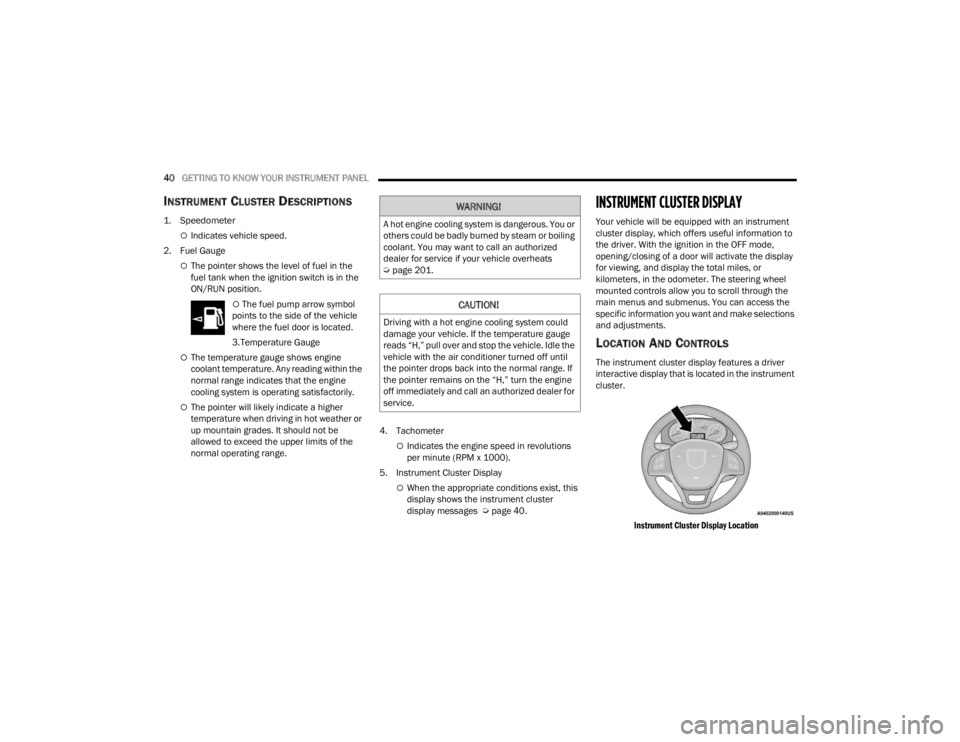
The instrument cluster display features a driver
interactive display that is located in the instrument
cluster.
Instrument Cluster Display Location
WARNING!
A hot engine cooling system is dangerous. You or
others could be badly burned by steam or boiling
coolant. You may want to call an authorized
dealer for service if your vehicle overheats
Úpage 201.
CAUTION!
Driving with a hot engine cooling system could
damage your vehicle. If the temperature gauge
reads “H,” pull over and stop the vehicle. Idle the
vehicle with the air conditioner turned off until
the pointer drops back into the normal range. If
the pointer remains on the “H,” turn the engine
off immediately and call an authorized dealer for
service.
22_VM_OM_EN_USC_t.book Page 40
Page 43 of 260
GETTING TO KNOW YOUR INSTRUMENT PANEL41
The menu items described below are an example
of what can be found in the vehicle's menu:
Dimmer
Speed Beep
Trip A / B (options are selectable through the
steering wheel stalk)
Buzzer Volume
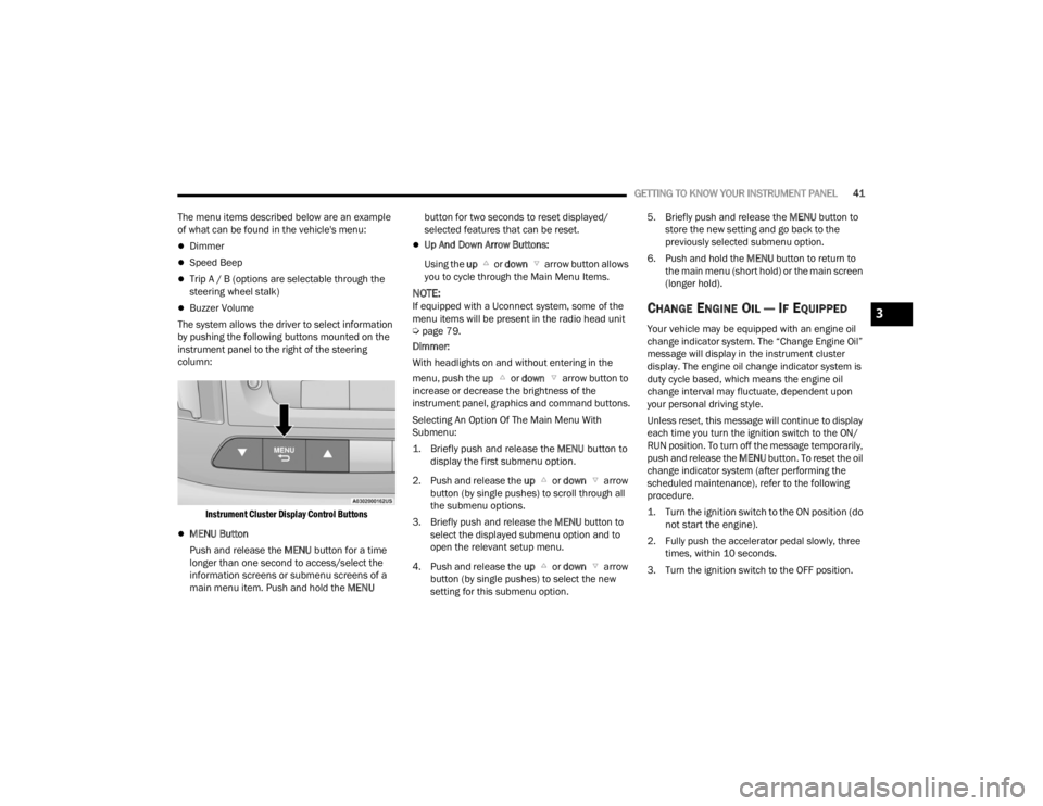
The system allows the driver to select information
by pushing the following buttons mounted on the
instrument panel to the right of the steering
column:
Instrument Cluster Display Control Buttons
MENU Button
Push and release the MENU button for a time
longer than one second to access/select the
information screens or submenu screens of a
main menu item. Push and hold the MENU button for two seconds to reset displayed/
selected features that can be reset.
Up And Down Arrow Buttons:
Using the up or down arrow button allows
you to cycle through the Main Menu Items.
NOTE:If equipped with a Uconnect system, some of the
menu items will be present in the radio head unit
Ú page 79.
Dimmer:
With headlights on and without entering in the
menu, push the up or down arrow button to
increase or decrease the brightness of the
instrument panel, graphics and command buttons.
Selecting An Option Of The Main Menu With
Submenu:
1. Briefly push and release the
MENU
button to
display the first submenu option.
2. Push and release the up or down arrow
button (by single pushes) to scroll through all
the submenu options.
3. Briefly push and release the MENU button to
select the displayed submenu option and to
open the relevant setup menu.
4. Push and release the up or down arrow
button (by single pushes) to select the new
setting for this submenu option. 5. Briefly push and release the MENU
button to
store the new setting and go back to the
previously selected submenu option.
6. Push and hold the MENU button to return to
the main menu (short hold) or the main screen
(longer hold).CHANGE ENGINE OIL — IF EQUIPPED
Your vehicle may be equipped with an engine oil
change indicator system. The “Change Engine Oil”
message will display in the instrument cluster
display. The engine oil change indicator system is
duty cycle based, which means the engine oil
change interval may fluctuate, dependent upon
your personal driving style.
Unless reset, this message will continue to display
each time you turn the ignition switch to the ON/
RUN position. To turn off the message temporarily,
push and release the MENU button. To reset the oil
change indicator system (after performing the
scheduled maintenance), refer to the following
procedure.
1. Turn the ignition switch to the ON position (do not start the engine).
2. Fully push the accelerator pedal slowly, three times, within 10 seconds.
3. Turn the ignition switch to the OFF position.
3
22_VM_OM_EN_USC_t.book Page 41
Page 45 of 260
GETTING TO KNOW YOUR INSTRUMENT PANEL43
Exit Menu
This is the last function that closes the cycle of
settings listed in the menu screen.
1. Pushing the
MENU
button briefly will return
the display to the standard screen without
storing.
2. Push the down arrow button to return to the
first menu item on the display.
TRIP COMPUTER
The Trip Computer is located in the instrument
cluster. It features a driver interactive display
(displays information such as trip information,
range, fuel consumption, average speed, and
travel time).
NOTE:The Uconnect System also has a Trip Computer
display and menus to customize the information
displayed in the cluster Ú page 79.
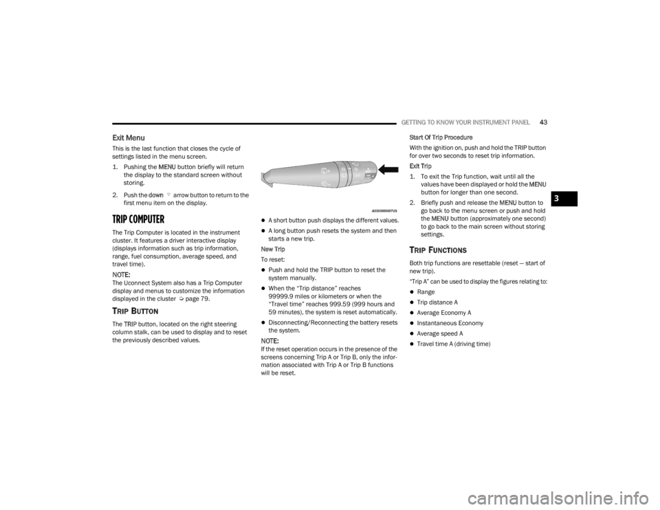
TRIP BUTTON
The TRIP button, located on the right steering
column stalk, can be used to display and to reset
the previously described values.
A short button push displays the different values.
A long button push resets the system and then
starts a new trip.
New Trip
To reset:
Push and hold the TRIP button to reset the
system manually.
When the “Trip distance” reaches
99999.9 miles or kilometers or when the
“Travel time” reaches 999.59 (999 hours and
59 minutes), the system is reset automatically.
Disconnecting/Reconnecting the battery resets
the system.
NOTE:If the reset operation occurs in the presence of the
screens concerning Trip A or Trip B, only the infor -
mation associated with Trip A or Trip B functions
will be reset. Start Of Trip Procedure
With the ignition on, push and hold the TRIP button
for over two seconds to reset trip information.
Exit Trip
1. To exit the Trip function, wait until all the
values have been displayed or hold the
MENU
button for longer than one second.
2. Briefly push and release the MENU button to
go back to the menu screen or push and hold
the MENU button (approximately one second)
to go back to the main screen without storing
settings.
TRIP FUNCTIONS
Both trip functions are resettable (reset — start of
new trip).
“Trip A” can be used to display the figures relating to:
Range
Trip distance A
Average Economy A
Instantaneous Economy
Average speed A
Travel time A (driving time)
3
22_VM_OM_EN_USC_t.book Page 43
Page 49 of 260

GETTING TO KNOW YOUR INSTRUMENT PANEL47
Transmission Fault Warning Light
This light will illuminate (together with a
message in the instrument cluster
display and a buzzer) to indicate a
transmission fault. Contact an
authorized dealer if the message remains after
restarting the engine.
Engine Oil Level Warning Light
This warning light appears on the panel
when the engine oil level falls below the
minimum recommended value. Restore
the correct engine oil level or contact an
authorized dealer for service.
YELLOW WARNING LIGHTS
Anti-Lock Brake System (ABS) Warning
Light
This light monitors the ABS. The light will
turn on when the ignition is placed in the
ON/RUN or MAR/ON/RUN position and
may stay on for as long as four seconds.
If the ABS light remains on or turns on while
driving, then the Anti-Lock portion of the brake
system is not functioning and service is required.
However, the conventional brake system will
continue to operate normally if the brake warning
light is not on. If the ABS light is on, the brake system should be
serviced as soon as possible to restore the
benefits of Anti-Lock Brakes. If the ABS light does
not turn on when the ignition is placed in the ON/
RUN or MAR/ON/RUN position, have the light
inspected by an authorized dealer.
Low Fuel Warning Light
When the fuel level reaches
approximately 2–3 gal (9–11 L) this
light will turn on, and remain on until
fuel is added.
Generic Warning Light
The Generic Warning Light will
illuminate if any of the following
conditions occur: Engine Oil Pressure
Sensor Failure, External Light Failure,
Parking Sensor Failure, Fuel Cut-Off Fail/
Intervention, Generic Failure on Trailer, or Air Bag
telltale recovery.
The telltale will blink in case of an Air Bag Warning
Light Failure. Contact an authorized dealer
immediately for service.
Tire Pressure Monitoring System (TPMS)
Warning Light
The warning light switches on and a
message is displayed to indicate that
the tire pressure is lower than the
recommended value and/or that slow
pressure loss is occurring. In these cases, optimal
tire duration and fuel consumption may not be
guaranteed.
Should one or more tires be in the condition
mentioned above, the display will show the
indications corresponding to each tire.
Each tire, including the spare (if provided), should be
checked monthly when cold and inflated to the
inflation pressure recommended by the vehicle
manufacturer on the vehicle placard or tire inflation
pressure label. If your vehicle has tires of a different
size than the size indicated on the vehicle placard or
tire inflation pressure label, you should determine the
proper tire inflation pressure for those tires.
CAUTION!
Do not continue driving with one or more flat
tires as handling may be compromised. Stop the
vehicle, avoiding sharp braking and steering. If a
tire puncture occurs, repair immediately using
the dedicated tire repair kit and contact an
authorized dealer as soon as possible.
3
22_VM_OM_EN_USC_t.book Page 47
Page 62 of 260
60STARTING AND OPERATING
NOTE:To select the proper gear position for maximum
deceleration (engine braking), move the gear
selector into the ERS position, then simply press
and hold it forward “-”. The transmission will shift
to the range from which the vehicle can best be
slowed down.
POWER STEERING
The standard power steering system provides
increased vehicle response and ease of
maneuverability. The system will provide
mechanical steering capability if power assist is
lost.
If for some reason the power assist is interrupted,
it will still be possible to steer your vehicle. Under
these conditions, you will observe a substantial
increase in steering effort, especially at very low
vehicle speeds and during parking maneuvers.
NOTE:
Increased noise levels at the end of the steering
wheel travel are considered normal and do not
indicate that there is a problem with the power
steering system.
Upon initial start-up in cold weather, the power
steering pump may make noise for a short
amount of time. This is due to the cold, thick
fluid in the steering system. This noise should
be considered normal, and it does not in any
way damage the steering system.
POWER STEERING FLUID CHECK
Checking the power steering fluid level at a defined
service interval is not required. The fluid should
only be checked if a leak is suspected, abnormal
noises are apparent, and/or the system is not
functioning as anticipated. Coordinate inspection
efforts through an authorized dealer. If necessary, add fluid to restore to the proper
indicated level. With a clean cloth, wipe any spilled
fluid from all surfaces Ú
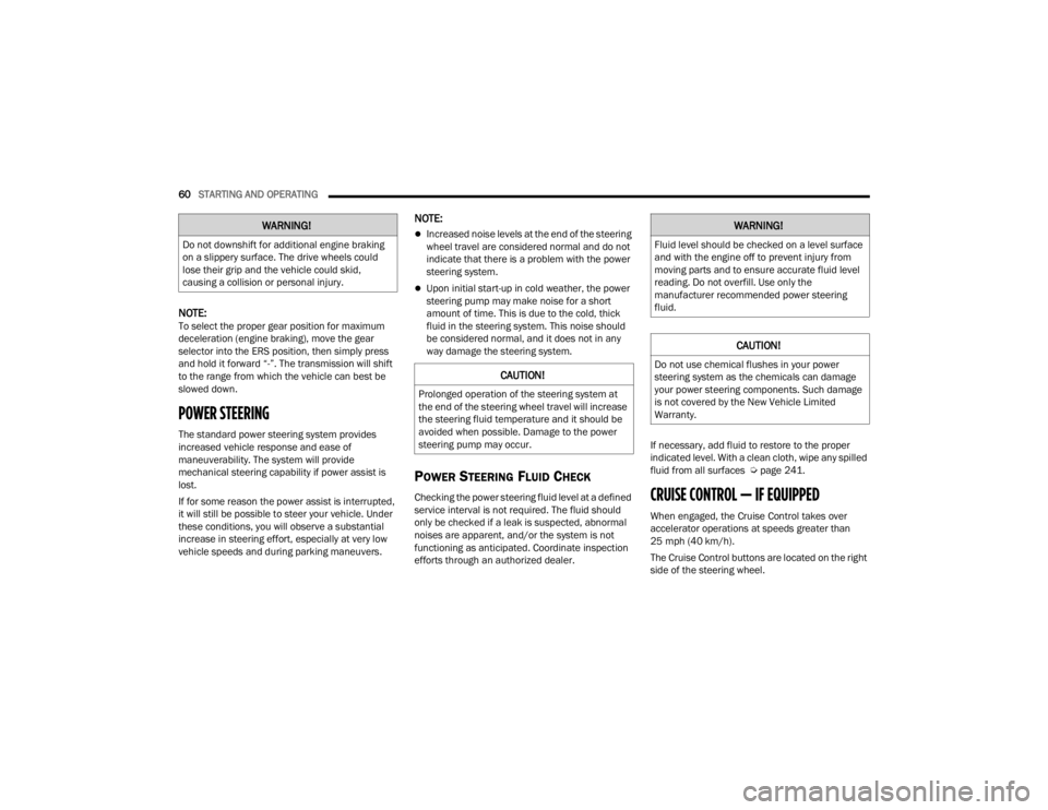
page 241.CRUISE CONTROL — IF EQUIPPED
When engaged, the Cruise Control takes over
accelerator operations at speeds greater than
25 mph (40 km/h).
The Cruise Control buttons are located on the right
side of the steering wheel.
WARNING!
Do not downshift for additional engine braking
on a slippery surface. The drive wheels could
lose their grip and the vehicle could skid,
causing a collision or personal injury.
CAUTION!
Prolonged operation of the steering system at
the end of the steering wheel travel will increase
the steering fluid temperature and it should be
avoided when possible. Damage to the power
steering pump may occur.
WARNING!
Fluid level should be checked on a level surface
and with the engine off to prevent injury from
moving parts and to ensure accurate fluid level
reading. Do not overfill. Use only the
manufacturer recommended power steering
fluid.
CAUTION!
Do not use chemical flushes in your power
steering system as the chemicals can damage
your power steering components. Such damage
is not covered by the New Vehicle Limited
Warranty.
22_VM_OM_EN_USC_t.book Page 60
Page 71 of 260
STARTING AND OPERATING69
Tongue Weight (TW)
The TW is the downward force exerted on the hitch
ball by the trailer. You must consider this as part of
the load on your vehicle.
Trailer Frontal Area
The frontal area is the maximum height multiplied
by the maximum width of the front of a trailer.
Trailer Sway Control (TSC)
The TSC can be a mechanical telescoping link that
can be installed between the hitch receiver and the
trailer tongue that typically provides adjustable
friction associated with the telescoping motion to
dampen any unwanted trailer swaying motions
while traveling.
If equipped, the electronic TSC recognizes a
swaying trailer and automatically applies individual
wheel brakes and/or reduces engine power to
attempt to eliminate the trailer sway.
Weight-Carrying Hitch
A weight-carrying hitch supports the trailer tongue
weight, just as if it were luggage located at a hitch
ball or some other connecting point of the vehicle.
These kinds of hitches are commonly used to tow
small and medium sized trailers.
Weight-Distributing Hitch
The weight-distributing hitch works by applying
leverage through spring (load) bars. They are
typically used for heavier loads to distribute trailer
tongue weight to the tow vehicle's front axle and
the trailer axle(s). When used in accordance with
the manufacturer's directions, it provides for a
more level ride, offering more consistent steering
and brake control thereby enhancing towing
safety. The addition of a friction/hydraulic sway
control also dampens sway caused by traffic and
crosswinds and contributes positively to tow vehicle and trailer stability. Trailer Sway Control
(TSC) and a weight distributing (load equalizing)
hitch are recommended for heavier Tongue
Weights (TW) and may be required depending on
vehicle and trailer configuration/loading to comply
with Gross Axle Weight Rating (GAWR)
requirements.WARNING!
An improperly adjusted Weight Distributing
Hitch system may reduce handling, stability,
braking performance, and could result in a
collision.
Weight Distributing Systems may not be
compatible with Surge Brake Couplers.
Consult with your hitch and trailer manufac-
turer or a reputable Recreational Vehicle
dealer for additional information.
4
22_VM_OM_EN_USC_t.book Page 69
Page 74 of 260
72STARTING AND OPERATING
(Continued)
Towing Requirements — Tires
Do not attempt to tow a trailer while using a
compact spare tire.
Do not drive more than 50 mph (80 km/h) when
towing while using a full size spare tire.
Proper tire inflation pressures are essential to
the safe and satisfactory operation of your
vehicle.
Check the trailer tires for proper tire inflation
pressures before trailer usage.
Check for signs of tire wear or visible tire
damage before towing a trailer.
When replacing tires with a higher load carrying
capacity they will not increase the vehicle's
GVWR and GAWR limits.
For further information Ú page 217.
WARNING!
Make certain that the load is secured in the
trailer and will not shift during travel. When
trailering cargo that is not fully secured,
dynamic load shifts can occur that may be
difficult for the driver to control. You could lose
control of your vehicle and have a collision.
When hauling cargo or towing a trailer, do not
overload your vehicle or trailer. Overloading
can cause a loss of control, poor performance
or damage to brakes, axle, engine, transmis -
sion, steering, suspension, chassis structure
or tires.
Safety chains must always be used between
your vehicle and trailer. Always connect the
chains to the hook retainers of the vehicle
hitch. Cross the chains under the trailer
tongue and allow enough slack for turning
corners.
Vehicles with trailers should not be parked on
a grade. When parking, apply the parking
brake on the tow vehicle. Put the tow vehicle
transmission in PARK. For four-wheel drive
vehicles, make sure the transfer case is not in
NEUTRAL. Always, block or "chock" the trailer
wheels.
GCWR must not be exceeded.
Total weight must be distributed between the
tow vehicle and the trailer such that the
following four ratings are not exceeded :
GVWR
GTW
GAWR
Tongue weight rating for the trailer hitch
utilized.
WARNING!
22_VM_OM_EN_USC_t.book Page 72
Page 92 of 260
90MULTIMEDIA
SAFETY AND GENERAL INFORMATION
Safety Guidelines
Please read the manual carefully before using the
system. It contains instructions on how to use the
system in a safe and effective manner.
Please read and follow these safety precautions.
Failure to do so may result in injury or property
damage.
Glance at the screen only when it is safe to do
so. If prolonged viewing of the screen is
required, park in a safe location and set the
parking brake.
Stop use immediately if a problem occurs.
Failure to do so may cause injury or damage to
the product. Return it to an authorized dealer to
repair.
Ensure the volume level of the system is set to a
level that still allows you to hear outside traffic
and emergency vehicles.
Safe Usage Of The Uconnect System
Your system is a sophisticated electronic
device. Do not let young children use your
system.
Permanent hearing loss may occur if you play
your music or sound system at loud volumes.
Exercise caution when setting the volume on
your system.
Keep drinks, rain and other sources of moisture
away from your system. Besides damage to your
system, moisture can cause electric shocks as
with any electronic device.
NOTE:Many features of this system are speed
dependent. For your own safety, it is not possible to
use some of the touchscreen features while the
vehicle is in motion.
Care And Maintenance
Touchscreen
Do not press the touchscreen with any hard or
sharp objects (pen, USB stick, jewelry, etc.)
which could scratch the touchscreen surface!
Do not spray any liquid or caustic chemicals
directly on the screen! Use a clean and dry
microfiber lens cleaning cloth in order to clean
the touchscreen.
If necessary, use a lint-free cloth dampened
with a cleaning solution, such as isopropyl
alcohol or an isopropyl alcohol and water solu -
tion ratio of 50:50. Be sure to follow the solvent
manufacturer's precautions and directions
Ú page 245.
WARNING!
ALWAYS drive safely with your hands on the
steering wheel. You have full responsibility and
assume all risks related to the use of the
Uconnect features and applications in this
vehicle. Only use Uconnect when it is safe to do
so. Failure to do so may result in an accident
involving serious injury or death.
CAUTION!
Do NOT attach any object to the touchscreen,
doing so can result in breaking the touchscreen.
22_VM_OM_EN_USC_t.book Page 90