2022 RAM PROMASTER CITY light
[x] Cancel search: lightPage 24 of 260
22GETTING TO KNOW YOUR VEHICLE
MIRRORS
INSIDE REARVIEW MIRROR
Manual Mirror — If Equipped
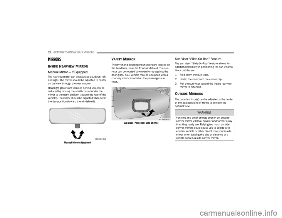
The rearview mirror can be adjusted up, down, left,
and right. The mirror should be adjusted to center
on the view through the rear window.
Headlight glare from vehicles behind you can be
reduced by moving the small control under the
mirror to the night position (toward the rear of the
vehicle). The mirror should be adjusted while set in
the day position (toward the windshield).
Manual Mirror Adjustment
VANITY MIRROR
The driver and passenger sun visors are located on
the headliner, near the front windshield. The sun
visor can be rotated downward or up against the
door glass. Your vehicle may be equipped with a
courtesy mirror located on the passenger sun
visor.
Sun Visor (Passenger Side Shown)
Sun Visor “Slide-On-Rod” Feature
The sun visor “Slide-On-Rod” feature allows for
additional flexibility in positioning the sun visor to
block out the sun.
1. Fold down the sun visor.
2. Unclip the visor from the corner clip.
3. Pull the sun visor toward the inside rearview mirror to extend it.
OUTSIDE MIRRORS
The outside mirror(s) can be adjusted to the center
of the adjacent lane of traffic to achieve the
optimal view.
WARNING!
Vehicles and other objects seen in an outside
convex mirror will look smaller and farther away
than they really are. Relying too much on side
convex mirrors could cause you to collide with
another vehicle or other object. Use your inside
mirror when judging the size or distance of a
vehicle seen in a side convex mirror.
22_VM_OM_EN_USC_t.book Page 22
Page 26 of 260
24GETTING TO KNOW YOUR VEHICLE
EXTERIOR LIGHTS
MULTIFUNCTION LEVER
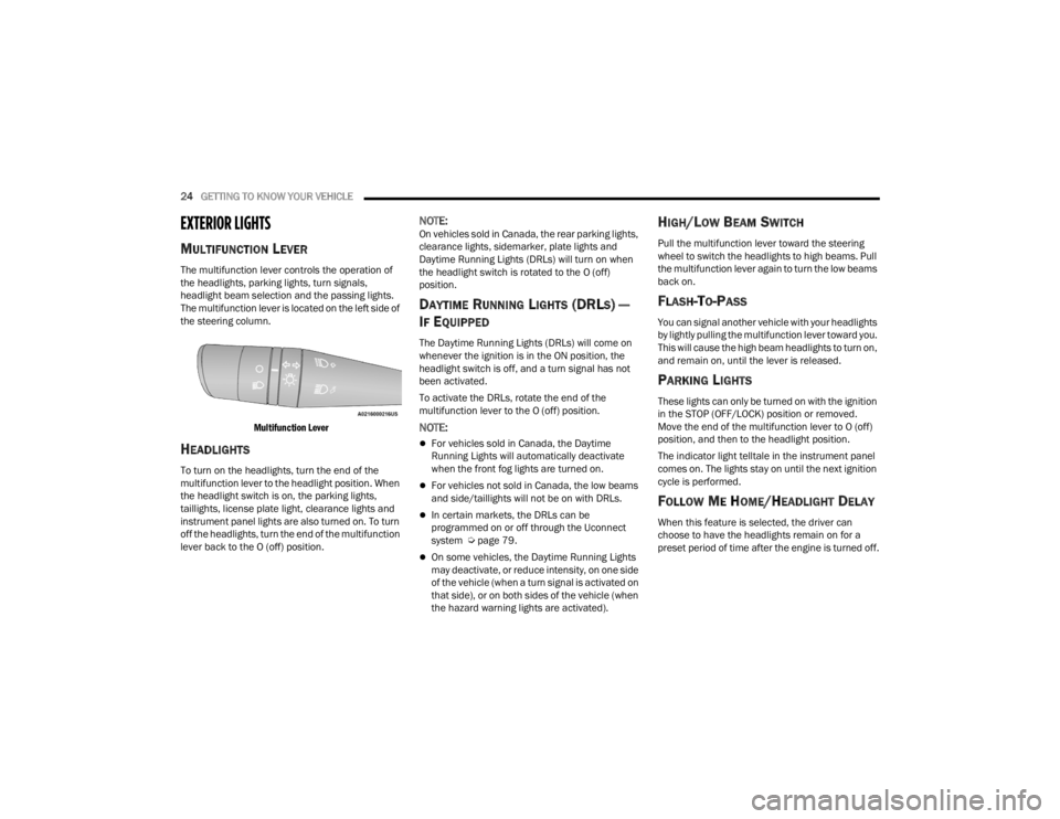
The multifunction lever controls the operation of
the headlights, parking lights, turn signals,
headlight beam selection and the passing lights.
The multifunction lever is located on the left side of
the steering column.
Multifunction Lever
HEADLIGHTS
To turn on the headlights, turn the end of the
multifunction lever to the headlight position. When
the headlight switch is on, the parking lights,
taillights, license plate light, clearance lights and
instrument panel lights are also turned on. To turn
off the headlights, turn the end of the multifunction
lever back to the O (off) position.
NOTE:On vehicles sold in Canada, the rear parking lights,
clearance lights, sidemarker, plate lights and
Daytime Running Lights (DRLs) will turn on when
the headlight switch is rotated to the O (off)
position.
DAYTIME RUNNING LIGHTS (DRLS) —
I
F EQUIPPED
The Daytime Running Lights (DRLs) will come on
whenever the ignition is in the ON position, the
headlight switch is off, and a turn signal has not
been activated.
To activate the DRLs, rotate the end of the
multifunction lever to the O (off) position.
NOTE:
For vehicles sold in Canada, the Daytime
Running Lights will automatically deactivate
when the front fog lights are turned on.
For vehicles not sold in Canada, the low beams
and side/taillights will not be on with DRLs.
In certain markets, the DRLs can be
programmed on or off through the Uconnect
system Ú page 79.
On some vehicles, the Daytime Running Lights
may deactivate, or reduce intensity, on one side
of the vehicle (when a turn signal is activated on
that side), or on both sides of the vehicle (when
the hazard warning lights are activated).
HIGH/LOW BEAM SWITCH
Pull the multifunction lever toward the steering
wheel to switch the headlights to high beams. Pull
the multifunction lever again to turn the low beams
back on.
FLASH-TO-PASS
You can signal another vehicle with your headlights
by lightly pulling the multifunction lever toward you.
This will cause the high beam headlights to turn on,
and remain on, until the lever is released.
PARKING LIGHTS
These lights can only be turned on with the ignition
in the STOP (OFF/LOCK) position or removed.
Move the end of the multifunction lever to O (off)
position, and then to the headlight position.
The indicator light telltale in the instrument panel
comes on. The lights stay on until the next ignition
cycle is performed.
FOLLOW ME HOME/HEADLIGHT DELAY
When this feature is selected, the driver can
choose to have the headlights remain on for a
preset period of time after the engine is turned off.
22_VM_OM_EN_USC_t.book Page 24
Page 27 of 260
GETTING TO KNOW YOUR VEHICLE25
Activation
Remove the key or turn the ignition to the STOP
(OFF/LOCK) position, and pull the multifunction
lever toward the steering wheel within two
minutes. Each time the lever is pulled, the
activation of the lights will be extended by 30
seconds. The activation of the lights can be
extended to a maximum of 210 seconds.
Deactivation
Pull the multifunction lever toward the steering
wheel and hold it for more than two seconds.
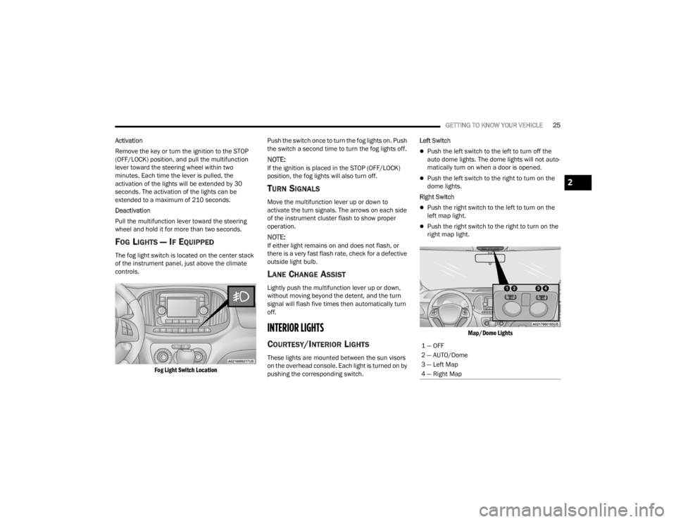
FOG LIGHTS — IF EQUIPPED
The fog light switch is located on the center stack
of the instrument panel, just above the climate
controls.
Fog Light Switch Location
Push the switch once to turn the fog lights on. Push
the switch a second time to turn the fog lights off.
NOTE:If the ignition is placed in the STOP (OFF/LOCK)
position, the fog lights will also turn off.
TURN SIGNALS
Move the multifunction lever up or down to
activate the turn signals. The arrows on each side
of the instrument cluster flash to show proper
operation.
NOTE:If either light remains on and does not flash, or
there is a very fast flash rate, check for a defective
outside light bulb.
LANE CHANGE ASSIST
Lightly push the multifunction lever up or down,
without moving beyond the detent, and the turn
signal will flash five times then automatically turn
off.
INTERIOR LIGHTS
COURTESY/INTERIOR LIGHTS
These lights are mounted between the sun visors
on the overhead console. Each light is turned on by
pushing the corresponding switch. Left Switch
Push the left switch to the left to turn off the
auto dome lights. The dome lights will not auto -
matically turn on when a door is opened.
Push the left switch to the right to turn on the
dome lights.
Right Switch
Push the right switch to the left to turn on the
left map light.
Push the right switch to the right to turn on the
right map light.
Map/Dome Lights
1 — OFF
2 — AUTO/Dome
3 — Left Map
4 — Right Map
2
22_VM_OM_EN_USC_t.book Page 25
Page 28 of 260
26GETTING TO KNOW YOUR VEHICLE
Rear Lights
Cargo Vehicle
Lateral Roof Light
This is located on the right side of the load
compartment.
Rear Roof Light
This is located on the rear panel of the load
compartment.
In auto-mode, the light comes on automatically
when you open the sliding doors and the rear swing
doors, and goes out when you close them.
Push the left-hand side of the lens to switch the
light off when the doors are open.
Push the right-hand side of the lens to switch
the light on when the doors are open.
Passenger Vehicle
The interior lamps are located in the center of the
roof, above the second row seating, and in the roof,
in the center of the rear load area. Second Row Seating And Rear Roof Lights
Operation
In auto-mode, the light comes on automatically
when you open the rear swing doors, and goes out
when you close them.
Push the left-hand side of the lens to switch the
light off when the doors are open.
Push the right-hand side of the lens to switch
the light on when the doors are open.
Cargo Compartment Light — If Equipped
The cargo compartment light comes on
automatically when the swing doors are opened
and turns off when the doors are closed.
WIPERS AND WASHERS
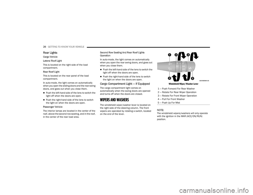
The windshield wiper/washer lever is located on
the right side of the steering column. The front
wipers are operated by rotating a switch, located
on the end of the lever.
Windshield Wiper/Washer Lever
NOTE:The windshield wipers/washers will only operate
with the ignition in the MAR (ACC/ON/RUN)
position.1 — Push Forward For Rear Washer
2 — Rotate For Rear Wiper Operation
3 — Rotate For Front Wiper Operation
4 — Pull For Front Washer
5 — Push Up For Mist
22_VM_OM_EN_USC_t.book Page 26
Page 32 of 260
30GETTING TO KNOW YOUR VEHICLE
Mode Control
Rotate this control to change the airflow
distribution mode. The airflow
distribution mode can be adjusted so air
comes from the instrument panel
outlets, floor outlets, defrost outlets and demist
outlets. The Mode settings are as follows:
Panel Mode
Air comes from the outlets in the
instrument panel. Each of these outlets
can be individually adjusted to direct the
flow of air. The air vanes of the center
outlets and outboard outlets can be moved up and
down or side to side to regulate airflow direction.
There is a shut-off wheel located below the air
vanes to shut off or adjust the amount of airflow
from these outlets.
Bi-Level Mode
Air comes from the instrument panel
outlets and floor outlets. A slight amount
of air is directed through the defrost and
side window demister outlets.
NOTE:Bi-Level mode is designed under comfort condi -
tions to provide cooler air out of the panel outlets
and warmer air from the floor outlets.
Floor Mode
Air comes from the floor outlets. A slight
amount of air is directed through the
defrost and side window demister
outlets.
Mix Mode
Air is directed through the floor, defrost,
and side window demister outlets. This
setting works best in cold or snowy
conditions that require extra heat to the
windshield. This setting is good for maintaining
comfort while reducing moisture on the
windshield.
OPERATING TIPS
Refer to the chart at the end of this section for
suggested control settings for various weather
conditions.
Summer Operation
The engine cooling system must be protected with
a high-quality antifreeze coolant to provide proper
corrosion protection and to protect against engine
overheating. OAT coolant (conforming to
MS.90032) is recommended Ú page 240.
Winter Operation
To ensure the best possible heater and defroster
performance, make sure the engine cooling
system is functioning properly and the proper
amount, type, and concentration of coolant is used
Úpage 240. Use of the Air Recirculation mode
during Winter months is not recommended
because it may cause window fogging.
Vacation/Storage
For information on maintaining the Climate Control
system when the vehicle is being stored for an
extended period of time, see Ú page 233.
Window Fogging
Vehicle windows tend to fog on the inside of the
glass in mild, rainy and/or humid weather. To clear
the windows, select Defrost or Mix mode and
increase the front blower speed. Do not use the
Recirculation mode without A/C for long periods,
as fogging may occur.
Outside Air Intake
Make sure the air intake, located directly in front of
the windshield, is free of obstructions, such as
leaves. Leaves collected in the air intake may
reduce airflow, and if they enter the air distribution
box, they could plug the water drains. In Winter
months, make sure the air intake is clear of ice,
slush, and snow.
22_VM_OM_EN_USC_t.book Page 30
Page 35 of 260
GETTING TO KNOW YOUR VEHICLE33
Load Compartment Power Outlet
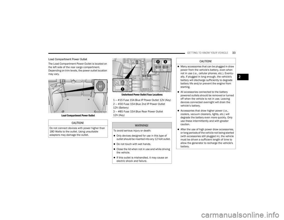
The Load Compartment Power Outlet is located on
the left side of the rear cargo compartment.
Depending on trim levels, the power outlet location
may vary.
Load Compartment Power Outlet Underhood Power Outlet Fuse Locations
CAUTION!
Do not connect devices with power higher than
180 Watts to the outlet. Using unsuitable
adapters may damage the outlet.
1 — #15 Fuse 15A Blue IP Power Outlet 12V (Key)
2 — #30 Fuse 15A Blue 2nd IP Power Outlet
12V (Battery)
3 — #85 Fuse 15A Blue Rear Power Outlet
12V (Key)
WARNING!
To avoid serious injury or death:
Only devices designed for use in this type of
outlet should be inserted into any 12 Volt outlet.
Do not touch with wet hands.
Close the lid when not in use and while driving
the vehicle.
If this outlet is mishandled, it may cause an
electric shock and failure.
CAUTION!
Many accessories that can be plugged in draw
power from the vehicle's battery, even when
not in use (i.e., cellular phones, etc.). Eventu
-
ally, if plugged in long enough, the vehicle's
battery will discharge sufficiently to degrade
battery life and/or prevent the engine from
starting.
All accessories connected to the battery
powered outlets should be removed or turned
off when the vehicle is not in use. Leaving
devices connected overnight will drain the
vehicle’s battery.
Accessories that draw higher power (i.e.,
coolers, vacuum cleaners, lights, etc.) will
degrade the battery even more quickly. Only
use these intermittently and with greater
caution.
After the use of high power draw accessories,
or long periods of the vehicle not being started
(with accessories still plugged in), the vehicle
must be driven a sufficient length of time to
allow the generator to recharge the vehicle's
battery.
2
22_VM_OM_EN_USC_t.book Page 33
Page 37 of 260
GETTING TO KNOW YOUR VEHICLE35
Power Windows System Initialization
The power windows may be reset if any of the
following occurs:
On the front doors:
Fuse or battery are disconnected when the
window is moving
50 window movements without ever closing
the window
On the rear doors (in addition to the conditions
for the front doors):
Fuse or battery are disconnected when the
window is moving
The auto-reverse system is activated while
the window is moving and the door is
opening
50 window movements without ever closing
the window
One door opening with the window moving,
without ever closing the door
Three doors opening with the window in
motion. During these maneuvers, the upper
stop position is never reached Proceed as follows for initialization:
1. Completely close the driver's door window,
keeping the window switch pushed for at
least five seconds after the (upper) end of
travel position.
2. Proceed in the same way on the passenger's window switches.
Rear Window Lockout Switch — If Equipped
The window lockout switch on the driver's door trim
panel allows you to disable the window controls on
the rear passenger doors. To disable the window
controls, push and release the window lockout
button (the indicator light on the button will turn
on). To enable the window controls, push and
release the window lockout button again (the
indicator light on the button will turn off).
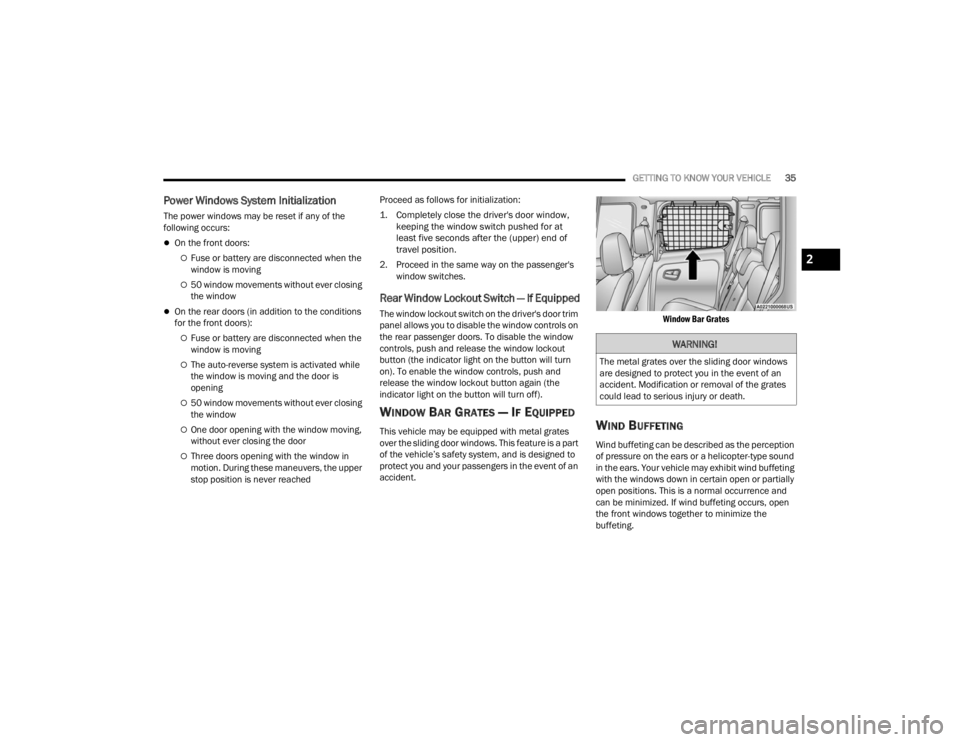
WINDOW BAR GRATES — IF EQUIPPED
This vehicle may be equipped with metal grates
over the sliding door windows. This feature is a part
of the vehicle’s safety system, and is designed to
protect you and your passengers in the event of an
accident.
Window Bar Grates
WIND BUFFETING
Wind buffeting can be described as the perception
of pressure on the ears or a helicopter-type sound
in the ears. Your vehicle may exhibit wind buffeting
with the windows down in certain open or partially
open positions. This is a normal occurrence and
can be minimized. If wind buffeting occurs, open
the front windows together to minimize the
buffeting.
WARNING!
The metal grates over the sliding door windows
are designed to protect you in the event of an
accident. Modification or removal of the grates
could lead to serious injury or death.
2
22_VM_OM_EN_USC_t.book Page 35
Page 43 of 260
GETTING TO KNOW YOUR INSTRUMENT PANEL41
The menu items described below are an example
of what can be found in the vehicle's menu:
Dimmer
Speed Beep
Trip A / B (options are selectable through the
steering wheel stalk)
Buzzer Volume
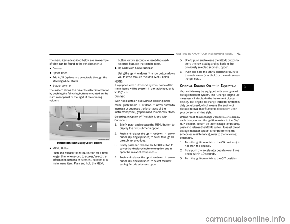
The system allows the driver to select information
by pushing the following buttons mounted on the
instrument panel to the right of the steering
column:
Instrument Cluster Display Control Buttons
MENU Button
Push and release the MENU button for a time
longer than one second to access/select the
information screens or submenu screens of a
main menu item. Push and hold the MENU button for two seconds to reset displayed/
selected features that can be reset.
Up And Down Arrow Buttons:
Using the up or down arrow button allows
you to cycle through the Main Menu Items.
NOTE:If equipped with a Uconnect system, some of the
menu items will be present in the radio head unit
Ú page 79.
Dimmer:
With headlights on and without entering in the
menu, push the up or down arrow button to
increase or decrease the brightness of the
instrument panel, graphics and command buttons.
Selecting An Option Of The Main Menu With
Submenu:
1. Briefly push and release the
MENU
button to
display the first submenu option.
2. Push and release the up or down arrow
button (by single pushes) to scroll through all
the submenu options.
3. Briefly push and release the MENU button to
select the displayed submenu option and to
open the relevant setup menu.
4. Push and release the up or down arrow
button (by single pushes) to select the new
setting for this submenu option. 5. Briefly push and release the MENU
button to
store the new setting and go back to the
previously selected submenu option.
6. Push and hold the MENU button to return to
the main menu (short hold) or the main screen
(longer hold).CHANGE ENGINE OIL — IF EQUIPPED
Your vehicle may be equipped with an engine oil
change indicator system. The “Change Engine Oil”
message will display in the instrument cluster
display. The engine oil change indicator system is
duty cycle based, which means the engine oil
change interval may fluctuate, dependent upon
your personal driving style.
Unless reset, this message will continue to display
each time you turn the ignition switch to the ON/
RUN position. To turn off the message temporarily,
push and release the MENU button. To reset the oil
change indicator system (after performing the
scheduled maintenance), refer to the following
procedure.
1. Turn the ignition switch to the ON position (do not start the engine).
2. Fully push the accelerator pedal slowly, three times, within 10 seconds.
3. Turn the ignition switch to the OFF position.
3
22_VM_OM_EN_USC_t.book Page 41