2022 RAM PROMASTER CITY change time
[x] Cancel search: change timePage 4 of 260
2
INTRODUCTION
SYMBOLS KEY ...........................................................7
VAN CONVERSIONS/CAMPERS ..............................7
VEHICLE MODIFICATIONS/ALTERATIONS .............7
SYMBOL GLOSSARY.................................................8
GETTING TO KNOW YOUR VEHICLE
KEYS ....................................................................... 10 Key Fob .............................................................10
SENTRY KEY ........................................................... 12
IGNITION SWITCH .................................................. 12
DOORS ................................................................... 13
Power Door Locks ............................................13
Auto Unlock Doors ............................................13
Sliding Side Door ..............................................13
Double Rear Swing Doors ................................15
Child-Protection Door Lock System.................15
STEERING WHEEL.................................................. 16
Tilt/Telescoping Steering Column ...................16
SEATS ...................................................................... 16
Manual Adjustment (Front Seats) ...................16
Folding Rear Seat — If Equipped .....................17
Heated Seats — If Equipped ............................18
Head Restraints ...............................................19 UCONNECT VOICE RECOGNITION ........................21
Introducing Voice Recognition.........................21
Basic Voice Commands ...................................21
Get Started .......................................................21
Additional Information .....................................21
MIRRORS ...............................................................22
Inside Rearview Mirror .....................................22
Vanity Mirror .....................................................22
Outside Mirrors ................................................22
EXTERIOR LIGHTS ..................................................24
Multifunction Lever ..........................................24
Headlights ........................................................24
Daytime Running Lights (DRLs) —
If Equipped .......................................................24
High/Low Beam Switch....................................24
Flash-To-Pass ..................................................24
Parking Lights ..................................................24
Follow Me Home/Headlight Delay ..................24
Fog Lights — If Equipped .................................25
Turn Signals ......................................................25
Lane Change Assist..........................................25
INTERIOR LIGHTS ..................................................25
Courtesy/Interior Lights ...................................25
WIPERS AND WASHERS ......................................26
Front Wiper Operation......................................27
Rear Wiper And Washer —If Equipped ............28 CLIMATE CONTROLS ............................................ 28
Manual Climate Control Descriptions And
Functions .......................................................... 28
Operating Tips .................................................. 30
INTERIOR STORAGE AND EQUIPMENT ............... 31
Storage ............................................................. 31
USB Control — If Equipped .............................. 32
Power Outlets .................................................. 32
WINDOWS ............................................................. 34
Power Window Controls —If Equipped ........... 34
Window Bar Grates — If Equipped .................. 35
Wind Buffeting .................................................35
HOOD....................................................................... 36
Opening............................................................. 36
Closing ..............................................................36
CARGO AREA FEATURES ...................................... 37
Rear Cargo Tie-Downs ..................................... 37
ROOF RACK — IF EQUIPPED................................. 37
GETTING TO KNOW YOUR
INSTRUMENT PANEL
INSTRUMENT CLUSTER......................................... 39
Instrument Cluster Descriptions ..................... 40
INSTRUMENT CLUSTER DISPLAY ....................... 40
Location And Controls...................................... 40
Change Engine Oil — If Equipped ................... 41
Instrument Cluster Display Menu Items ......... 42
22_VM_OM_EN_USC_t.book Page 2
Page 8 of 260

6
INTRODUCTION
Dear Customer,
Congratulations on selecting your new Ram. Be assured that it represents precision workmanship, distinctive styling, and high quality. This Owner’s Manual has
been prepared with the assistance of service and engineering specialists to acquaint you with the operation and maintenance of your vehicle. It is supplemented
by customer-oriented documents. Within this information, you will find a description of the services that FCA US LLC offers to its customers as well as the details
of the terms and conditions for maintaining its validity. Please take the time to read all of these publications carefully before driving your vehicle for the first time.
Following the instructions, recommendations, tips, and important warnings in this manual will help ensure safe and enjoyable operation of your vehicle. Be sure
you are familiar with all vehicle controls, particularly those used for braking, steering, transmission, and transfer case shifting (if equipped). Learn how your
vehicle handles on different road surfaces. Your driving skills will improve with experience.
This Owner’s Manual describes all versions of this vehicle. Options and equipment dedicated to specific markets or versions are not expressly indicated in
the text. Therefore, you should only consider the information that is related to the trim level, engine, and version that you have purchased. Any content
introduced throughout the Owner’s Information, which may or may not be applicable to your vehicle, will be identified with the wording “If Equipped”. All data
contained in this publication are intended to help you use your vehicle in the best possible way. FCA US LLC aims at a constant improvement of the vehicles
produced. For this reason, it reserves the right to make changes to the model described for technical and/or commercial reasons. For further information,
contact an authorized dealer.
When it comes to service, remember that authorized dealers know your Ram best, have factory-trained technicians and genuine Mopar® parts, and care about
your satisfaction.
22_VM_OM_EN_USC_t.book Page 6
Page 27 of 260
GETTING TO KNOW YOUR VEHICLE25
Activation
Remove the key or turn the ignition to the STOP
(OFF/LOCK) position, and pull the multifunction
lever toward the steering wheel within two
minutes. Each time the lever is pulled, the
activation of the lights will be extended by 30
seconds. The activation of the lights can be
extended to a maximum of 210 seconds.
Deactivation
Pull the multifunction lever toward the steering
wheel and hold it for more than two seconds.
FOG LIGHTS — IF EQUIPPED
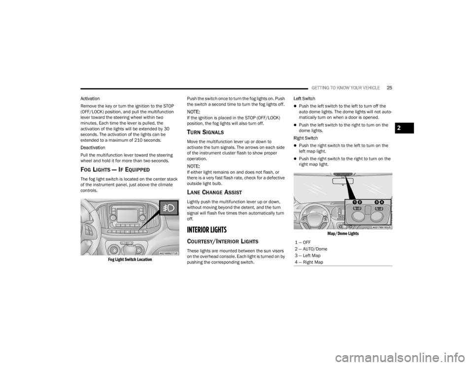
The fog light switch is located on the center stack
of the instrument panel, just above the climate
controls.
Fog Light Switch Location
Push the switch once to turn the fog lights on. Push
the switch a second time to turn the fog lights off.
NOTE:If the ignition is placed in the STOP (OFF/LOCK)
position, the fog lights will also turn off.
TURN SIGNALS
Move the multifunction lever up or down to
activate the turn signals. The arrows on each side
of the instrument cluster flash to show proper
operation.
NOTE:If either light remains on and does not flash, or
there is a very fast flash rate, check for a defective
outside light bulb.
LANE CHANGE ASSIST
Lightly push the multifunction lever up or down,
without moving beyond the detent, and the turn
signal will flash five times then automatically turn
off.
INTERIOR LIGHTS
COURTESY/INTERIOR LIGHTS
These lights are mounted between the sun visors
on the overhead console. Each light is turned on by
pushing the corresponding switch. Left Switch
Push the left switch to the left to turn off the
auto dome lights. The dome lights will not auto -
matically turn on when a door is opened.
Push the left switch to the right to turn on the
dome lights.
Right Switch
Push the right switch to the left to turn on the
left map light.
Push the right switch to the right to turn on the
right map light.
Map/Dome Lights
1 — OFF
2 — AUTO/Dome
3 — Left Map
4 — Right Map
2
22_VM_OM_EN_USC_t.book Page 25
Page 32 of 260
30GETTING TO KNOW YOUR VEHICLE
Mode Control
Rotate this control to change the airflow
distribution mode. The airflow
distribution mode can be adjusted so air
comes from the instrument panel
outlets, floor outlets, defrost outlets and demist
outlets. The Mode settings are as follows:
Panel Mode
Air comes from the outlets in the
instrument panel. Each of these outlets
can be individually adjusted to direct the
flow of air. The air vanes of the center
outlets and outboard outlets can be moved up and
down or side to side to regulate airflow direction.
There is a shut-off wheel located below the air
vanes to shut off or adjust the amount of airflow
from these outlets.
Bi-Level Mode
Air comes from the instrument panel
outlets and floor outlets. A slight amount
of air is directed through the defrost and
side window demister outlets.
NOTE:Bi-Level mode is designed under comfort condi -
tions to provide cooler air out of the panel outlets
and warmer air from the floor outlets.
Floor Mode
Air comes from the floor outlets. A slight
amount of air is directed through the
defrost and side window demister
outlets.
Mix Mode
Air is directed through the floor, defrost,
and side window demister outlets. This
setting works best in cold or snowy
conditions that require extra heat to the
windshield. This setting is good for maintaining
comfort while reducing moisture on the
windshield.
OPERATING TIPS
Refer to the chart at the end of this section for
suggested control settings for various weather
conditions.
Summer Operation
The engine cooling system must be protected with
a high-quality antifreeze coolant to provide proper
corrosion protection and to protect against engine
overheating. OAT coolant (conforming to
MS.90032) is recommended Ú page 240.
Winter Operation
To ensure the best possible heater and defroster
performance, make sure the engine cooling
system is functioning properly and the proper
amount, type, and concentration of coolant is used
Úpage 240. Use of the Air Recirculation mode
during Winter months is not recommended
because it may cause window fogging.
Vacation/Storage
For information on maintaining the Climate Control
system when the vehicle is being stored for an
extended period of time, see Ú page 233.
Window Fogging
Vehicle windows tend to fog on the inside of the
glass in mild, rainy and/or humid weather. To clear
the windows, select Defrost or Mix mode and
increase the front blower speed. Do not use the
Recirculation mode without A/C for long periods,
as fogging may occur.
Outside Air Intake
Make sure the air intake, located directly in front of
the windshield, is free of obstructions, such as
leaves. Leaves collected in the air intake may
reduce airflow, and if they enter the air distribution
box, they could plug the water drains. In Winter
months, make sure the air intake is clear of ice,
slush, and snow.
22_VM_OM_EN_USC_t.book Page 30
Page 43 of 260
GETTING TO KNOW YOUR INSTRUMENT PANEL41
The menu items described below are an example
of what can be found in the vehicle's menu:
Dimmer
Speed Beep
Trip A / B (options are selectable through the
steering wheel stalk)
Buzzer Volume
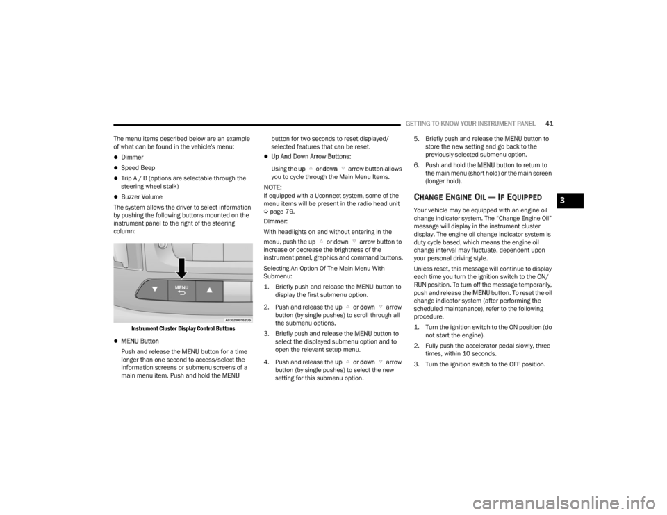
The system allows the driver to select information
by pushing the following buttons mounted on the
instrument panel to the right of the steering
column:
Instrument Cluster Display Control Buttons
MENU Button
Push and release the MENU button for a time
longer than one second to access/select the
information screens or submenu screens of a
main menu item. Push and hold the MENU button for two seconds to reset displayed/
selected features that can be reset.
Up And Down Arrow Buttons:
Using the up or down arrow button allows
you to cycle through the Main Menu Items.
NOTE:If equipped with a Uconnect system, some of the
menu items will be present in the radio head unit
Ú page 79.
Dimmer:
With headlights on and without entering in the
menu, push the up or down arrow button to
increase or decrease the brightness of the
instrument panel, graphics and command buttons.
Selecting An Option Of The Main Menu With
Submenu:
1. Briefly push and release the
MENU
button to
display the first submenu option.
2. Push and release the up or down arrow
button (by single pushes) to scroll through all
the submenu options.
3. Briefly push and release the MENU button to
select the displayed submenu option and to
open the relevant setup menu.
4. Push and release the up or down arrow
button (by single pushes) to select the new
setting for this submenu option. 5. Briefly push and release the MENU
button to
store the new setting and go back to the
previously selected submenu option.
6. Push and hold the MENU button to return to
the main menu (short hold) or the main screen
(longer hold).CHANGE ENGINE OIL — IF EQUIPPED
Your vehicle may be equipped with an engine oil
change indicator system. The “Change Engine Oil”
message will display in the instrument cluster
display. The engine oil change indicator system is
duty cycle based, which means the engine oil
change interval may fluctuate, dependent upon
your personal driving style.
Unless reset, this message will continue to display
each time you turn the ignition switch to the ON/
RUN position. To turn off the message temporarily,
push and release the MENU button. To reset the oil
change indicator system (after performing the
scheduled maintenance), refer to the following
procedure.
1. Turn the ignition switch to the ON position (do not start the engine).
2. Fully push the accelerator pedal slowly, three times, within 10 seconds.
3. Turn the ignition switch to the OFF position.
3
22_VM_OM_EN_USC_t.book Page 41
Page 44 of 260
42GETTING TO KNOW YOUR INSTRUMENT PANEL
NOTE:If the indicator message illuminates when you start
the vehicle, the oil change indicator system did not
reset. If necessary, repeat this procedure.
INSTRUMENT CLUSTER DISPLAY MENU
I
TEMS
Speed Beep
This function is used to set a speed limit (MPH or
km/h); the driver is alerted when this limit is
exceeded.
To set the desired speed limit:
1. Push the
MENU
button briefly. The display will
show the wording (SPEED BEEP) and the unit
(MPH) or (km/h) previously set.
2. If the function is on, push and release the up
or down arrow button to select the required
speed limit and then push MENU to confirm.
NOTE:The speed may be set in the range from 20 to
125 mph (30 to 200 km/h) according to the previ -
ously chosen unit.
The setting will increase/decrease by five units
each time the up or down arrow button is
pushed. Hold down the up or down arrow
button to automatically increase/decrease the setting rapidly. Complete the adjustment when you
approach the desired value.
Push the
MENU button briefly to return to the menu
screen or hold the MENU button down to return to
the standard screen without storing.
To cancel the setting:
1. Briefly push the
MENU
button, “ON” will flash
in the display.
2. Push the down arrow button, “OFF” will
flash in the display.
3. Push the MENU button briefly to return to the
menu screen or hold the MENU button down to
return to the standard screen without storing.
Trip B Data
This function can be used to activate (On) or
deactivate (Off) the Trip B display (Partial Trip)
Ú page 43.
To switch the function On/Off:
1. Push the
MENU
button briefly. The display will
flash On or Off according to the previous
setting.
2. Push and release the up or down arrow
button to select. Push the
MENU button briefly to return to the menu
screen or hold the MENU button down to return to
the standard screen without storing.
Buzzer Volume
With this function, the volume of the acoustic
signal which accompanies the display of failure/
warning can be adjusted according to seven levels.
To set the desired volume:
1. Push the
MENU
button, the previously set
volume level will flash on the display.
2. Push and release the up or down arrow
button to adjust.
3. Push the MENU button to return to the menu
screen or hold the MENU button down to
return to the standard screen without storing.
Seat Belt Buzzer
Only shows in the instrument cluster display if the
seat belt reminder was previously deactivated by
an authorized dealer.
NOTE:This is a one-time occurrence to enable the
acoustic signal.
22_VM_OM_EN_USC_t.book Page 42
Page 46 of 260

44GETTING TO KNOW YOUR INSTRUMENT PANEL
“Trip B” can be used to display the figures relating to:
Trip distance B
Average Economy B
Average speed B
Travel time B (driving time)
NOTE:“Trip B” functions may be excluded (see “Trip B
Data”). Range and Instantaneous Economy cannot
be reset.
VALUES DISPLAYED
Range
This indicates the distance which may be traveled
with the fuel remaining in the tank, assuming that
driving conditions will not change. The message “----”
will appear on the display in the following cases:
Distance less than 30 miles (or 50 km).
The vehicle is parked for a long time with the
engine running.
NOTE:The range depends on several factors: driving
style, type of route (freeway, residential, mountain
roads, etc.), conditions of use of the vehicle (load,
tire pressure, etc.). Trip planning must take into
account the above notes.
Travel Distance
This value shows the distance covered since the
last reset.
Average Fuel Consumption
This value shows the approximate average
consumption since the last reset.
Current Fuel Consumption
This indicates the fuel consumption. The value is
constantly updated. The message “----” will appear
on the display if the vehicle is parked with the
engine running.
Average Speed
This value shows the vehicle's average speed as a
function of the overall time elapsed since the last
reset.
Travel Time
This value shows the time elapsed since the last
reset.
WARNING LIGHTS AND MESSAGES
The warning/indicator lights will illuminate in the
instrument panel together with a dedicated
message and/or acoustic signal when applicable.
These indications are indicative and precautionary
and as such must not be considered as exhaustive
and/or alternative to the information contained in
the Owner’s Manual, which you are advised to read
carefully in all cases. Always refer to the information
in this chapter in the event of a failure indication. All
active telltales will display first if applicable. The
system check menu may appear different based
upon equipment options and current vehicle status.
Some telltales are optional and may not appear.
RED WARNING LIGHTS
Air Bag Warning Light
This light will turn on for four to eight
seconds as a bulb check when the
ignition is placed in the ON/RUN or
MAR/ON/RUN position. If the light is
either not on during startup, stays on, or turns on
while driving, have the system inspected by an
authorized dealer as soon as possible. This light
will illuminate with a single chime when a fault with
the Air Bag Warning Light has been detected, it will
stay on until the fault is cleared. If the light comes
on intermittently or remains on while driving, have
an authorized dealer service the vehicle
immediately.
22_VM_OM_EN_USC_t.book Page 44
Page 61 of 260

STARTING AND OPERATING59
If the transmission becomes extremely hot, the
Transmission Temperature Warning Light may
illuminate and the transmission may operate
differently until the transmission cools down.
During cold temperatures, transmission
operation may be modified depending on engine
and transmission temperature as well as vehicle
speed. This feature improves warm up time of the
engine and transmission to achieve maximum
efficiency. Engagement of the torque converter
clutch, and shifts into EIGHTH or NINTH gear, are
inhibited until the transmission fluid is warm
Ú
page 59. Normal operation will resume once
the transmission temperature has risen to a
suitable level.
Transmission Limp Home Mode
Transmission function is monitored electronically
for abnormal conditions. If a condition is detected
that could result in transmission damage,
Transmission Limp Home Mode is activated. In this
mode, the transmission may operate only in a fixed
gear, or may remain in NEUTRAL. The Malfunction
Indicator Light (MIL) may be illuminated. Limp
Home Mode may allow the vehicle to be driven to
an authorized dealer for service without damaging
the transmission. In the event of a momentary problem, the
transmission can be reset to regain all forward
gears by performing the following steps:
1. Stop the vehicle.
2. Shift the transmission into PARK.
3. Turn the ignition OFF.
4. Wait approximately 10 seconds.
5. Restart the engine.
6. Shift into the desired gear range. If the
problem is no longer detected, the
transmission will return to normal operation.
NOTE:
Even if the transmission can be reset, we recommend
that you visit an authorized dealer at your earliest
possible convenience. An authorized dealer has diag -
nostic equipment to assess the condition of your
transmission. If the transmission cannot be reset,
authorized dealer service is required.
Torque Converter Clutch
A feature designed to improve fuel economy has
been included in the automatic transmission on
your vehicle. A clutch within the torque converter
engages automatically at calibrated speeds. This
may result in a slightly different feeling or response
during normal operation in the upper gears. When
the vehicle speed drops or during some
accelerations, the clutch automatically
disengages.
NOTE:The torque converter clutch will not engage until
the transmission fluid is warm [usually after 1 to
3 miles (2 to 5 km) of driving]. Because the engine
speed is higher when the torque converter clutch is
not engaged, it may seem as if the transmission is
not shifting properly when cold. This is normal. The
torque converter clutch will function normally once
the transmission is sufficiently warm.
Electronic Range Select (ERS) Operation
The ERS shift control allows the driver to limit the
highest available gear. For example, if you set the
transmission gear limit to FIFTH gear, the
transmission will not shift above FIFTH gear, but
will shift through the lower gears normally.
You can switch between DRIVE and ERS mode at
any vehicle speed. When the gear selector is in the
DRIVE position, the transmission will operate
automatically, shifting between all available gears.
Moving the gear selector to the ERS position (beside
DRIVE) will activate ERS mode, display the current
gear in the instrument cluster, and set that gear as
the top available gear. Once in ERS mode, moving
the gear selector forward “-” or rearward “+” will
change the top available gear, which will be
displayed in the instrument cluster.
To exit ERS mode, simply return the gear selector
to the DRIVE position.4
22_VM_OM_EN_USC_t.book Page 59