2022 NISSAN TITAN lights
[x] Cancel search: lightsPage 217 of 635

To activate the trailer light check function
with your Intelligent Key, perform the
following:
1. Aim the Intelligent Key at the vehicle.
2. Press and release the
LOCK
button.
3. Within 2 seconds, press and hold the
LOCK button again for at least 2
seconds, until the horn beeps once and
the park lights turn on.
The following events will occur:
• The lef t turn signal light on the vehicle and the trailer will flash for 5 seconds.
• The right turn signal light on the vehicle and the trailer will flash for 5 seconds.
• The brake lights on the vehicle and the trailer will turn ON for 5 seconds.
NOTE:
If the ignition switch is in the OFF po-
sition, the park lights will turn off af ter
the events above occur. If ignition
switch is in the ON position, lights will
stay on for 45 seconds af ter trailer
light check. If the trailer lights do not
work properly, check the connections
and bulbs. If the vehicle lights do not
turn on, check the bulbs. If the trailer
light check routine fails to start, en-
sure the following vehicle conditions:
• The vehicle is NOT moving, 0 mph (0 km/h)
• Brake switch is NOT depressed
• Lef t or right flasher is OFF
• Trailer light check configuration is NOT disabled and available in the meter
towing settings
• The hazard switch is NOT turned ON
• The shif t position is fully in P (Park) position
• Vehicle is within Remote Keyless Entry range
Answer back horn feature
If desired, the horn beep feature can be
deactivated using the Intelligent Key.
To deactivate: Press and hold the
andbuttonsfor at least 2 seconds.
The hazard warning lights will flash three
times to confirm that the horn beep fea-
ture has been deactivated.
To activate: Press and hold the
andbuttonsfor at least 2 seconds once
more.
The hazard warning lights will flash once
and the horn will sound once to confirm
that the horn beep feature has been
reactivated.
Deactivating the horn beep feature does
not silence the horn if the alarm is
triggered.
Pre-driving checks and adjustments3-17
Page 221 of 635
CAUTION
When the Intelligent Key battery is dis-
charged or other strong radio wave
sources are present near the operating
location, the Intelligent Key operating
range becomes narrower, and the Intel-
ligent Key may not function properly.
The Remote Engine Start function can only
be used when the Intelligent Key is within
the specified operating range from the
vehicle.
The Remote Engine Start operating range
is approximately 197 f t (60 m) from the
vehicle.
REMOTE STARTING THE VEHICLE
To use the Remote Engine Start feature to
start the engine perform the following:
1. Aim the Intelligent Key at the vehicle.
2. Press the
button to lock all doors.
3. Within 5 seconds press and hold the
button until the turn signal lights
flash and the tail lamps turn on. If the
vehicle is not within view press and hold
the
button for at least 2 seconds. The following events will occur when the
engine starts:
• The parking lights will turn on and remain
on as long as the engine is running.
• The doors will be locked and the climate control system may come on.
• The engine will continue to run for 10 min- utes. Repeat the steps to extend the time
for an additional 10 minutes. For addi-
tional information, see “Extending engine
run time” (P. 3-21).
Press and hold the brake then push the
push-button ignition switch to the ON po-
sition before driving. For additional infor-
mation, see “Driving the vehicle” (P. 5-18)).
EXTENDING ENGINE RUN TIME
The Remote Engine Start feature can be
extended one time by performing the
steps listed in “Remote starting the vehicle”
in this section. Run time will be calculated
as follows:
• The first 10 minute run time will start when the Remote Engine Start function is
performed. • The second 10 minutes will start immedi-
ately when the Remote Engine Start
function is performed again. For example,
if the engine has been running for 5 min-
utes, and 10 minutes are added, the en-
gine will run for a total of 15 minutes.
• Extending engine run time will count to- wards the two Remote Engine Start limit.
A maximum of two Remote Engine Starts,
or a single Remote Engine Start with an
extension, are allowed between ignition
cycles. The ignition switch must be cycled
to the ON position and then back to the
OFF position before the Remote Engine
Start procedure can be used again.
CANCELING A REMOTE ENGINE
START
To cancel a Remote Engine Start, perform
one of the following:
• Aim the Intelligent Key at the vehicle and press
until the parking lights turn off.
• Turn on the hazard warning flashers.
• Cycle the ignition switch on and then off.
• The extended engine run time has expired.
• The first 10 minute timer has expired.
• The engine hood has been opened.
Pre-driving checks and adjustments3-21
Page 222 of 635

• The shif t lever is moved out of park.
• The alarm sounds due to illegal entry intothe vehicle.
• The ignition switch is pushed without an Intelligent Key in the vehicle.
• The ignition switch is pushed with an In- telligent Key in the vehicle but the brake
pedal is not depressed.
CONDITIONS THE REMOTE ENGINE
START WILL NOT WORK
The Remote Engine Start will not operate if
any of the following conditions are present:
• The ignition switch is placed in the ONposition.
• The hood is not securely closed.
• The hazard warning lights are on.
• The engine is still running. The engine must be completely stopped. Wait at
least 6 seconds if the engine goes from
running to off. This is not applicable when
extending engine run time.
• The
button is not pressed and held
for at least 2 seconds.
• The
button is not pressed and held
within 5 seconds of pressing the lock
button. • The brake is pressed.
• The doors are not closed and locked.
• The Key System Error Light remains solid
in the vehicle information display.
• The alarm sounds due to illegal entry into the vehicle.
• Two Remote Engine Starts, or a single Remote Engine Start with an extension,
have already been used.
• The vehicle is not in P (Park).
• There is a detected registered key already inside of the vehicle.
The Remote Engine Start Mode (if so
equipped) may display a warning or indica-
tor in the vehicle information display. For
additional information, see “Vehicle infor-
mation display” (P. 2-23).
3-22Pre-driving checks and adjustments
Page 229 of 635
CARD HOLDER (driver’s side only)
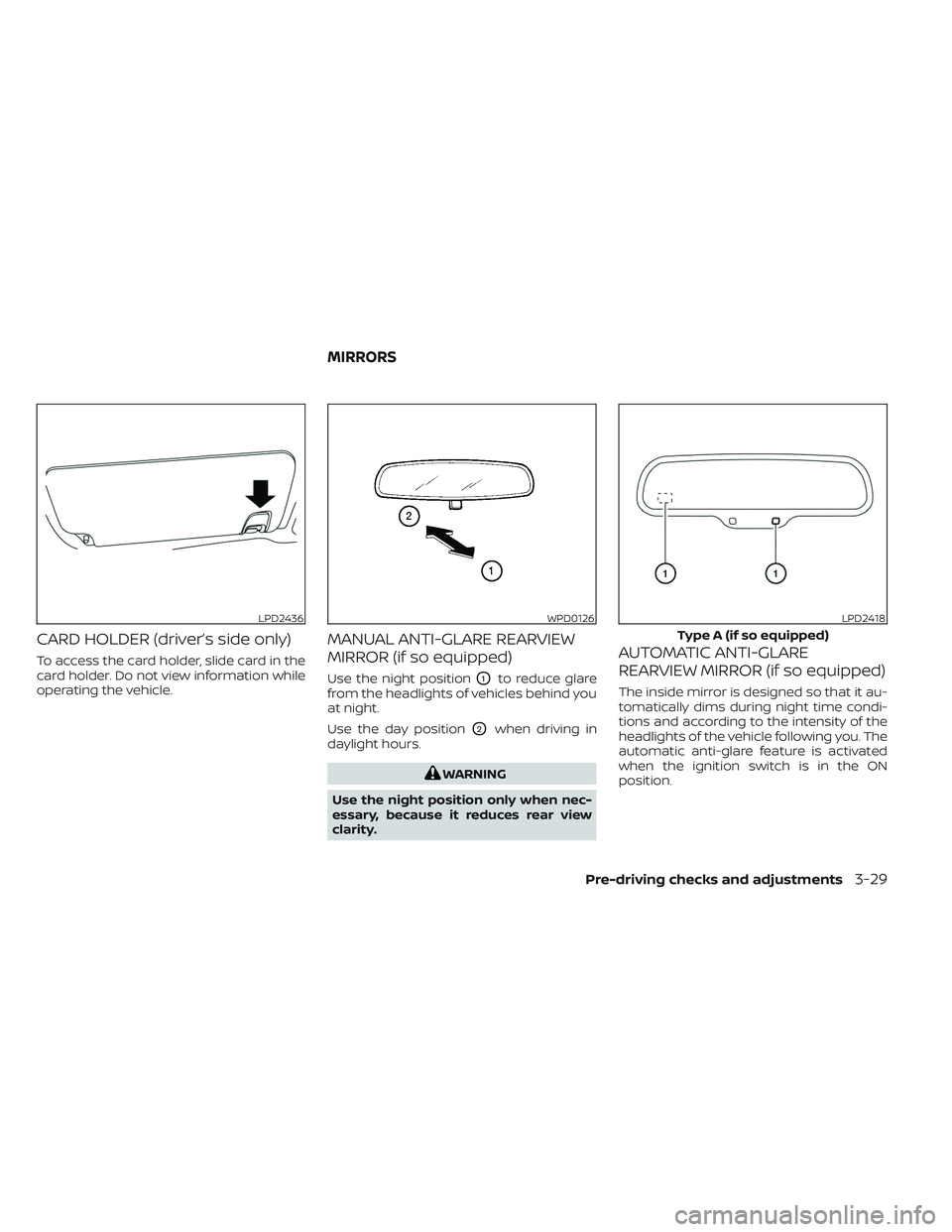
To access the card holder, slide card in the
card holder. Do not view information while
operating the vehicle.
MANUAL ANTI-GLARE REARVIEW
MIRROR (if so equipped)
Use the night positionO1to reduce glare
from the headlights of vehicles behind you
at night.
Use the day position
O2when driving in
daylight hours.
WARNING
Use the night position only when nec-
essary, because it reduces rear view
clarity.
AUTOMATIC ANTI-GLARE
REARVIEW MIRROR (if so equipped)
The inside mirror is designed so that it au-
tomatically dims during night time condi-
tions and according to the intensity of the
headlights of the vehicle following you. The
automatic anti-glare feature is activated
when the ignition switch is in the ON
position.
LPD2436WPD0126LPD2418
Type A (if so equipped)
MIRRORS
Pre-driving checks and adjustments3-29
Page 233 of 635
Power folding outside mirrors (if
so equipped)
CAUTION
Do not manually fold the power folding
mirrors. Manually folding the mirrors
can damage the mirrors.
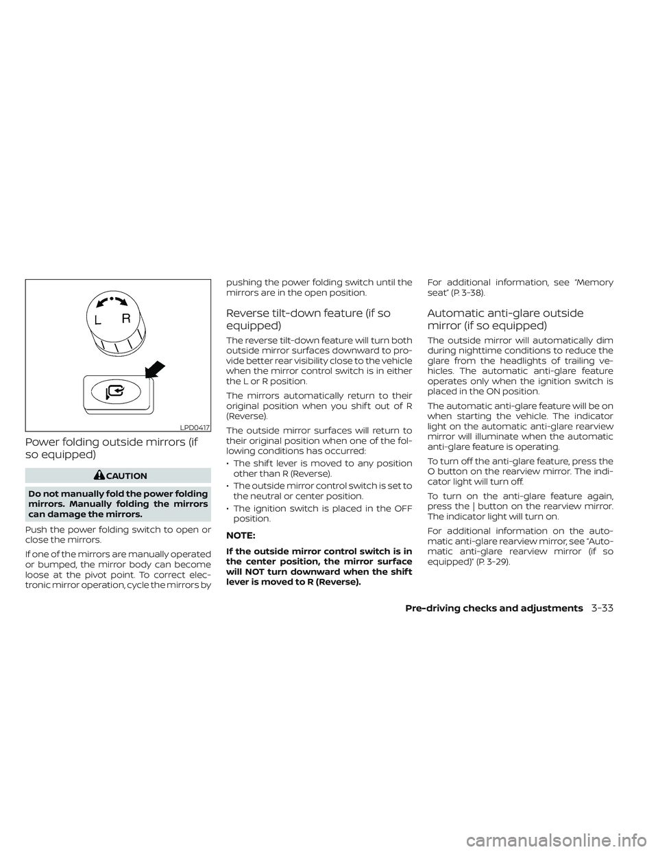
Push the power folding switch to open or
close the mirrors.
If one of the mirrors are manually operated
or bumped, the mirror body can become
loose at the pivot point. To correct elec-
tronic mirror operation, cycle the mirrors by pushing the power folding switch until the
mirrors are in the open position.
Reverse tilt-down feature (if so
equipped)
The reverse tilt-down feature will turn both
outside mirror surfaces downward to pro-
vide better rear visibility close to the vehicle
when the mirror control switch is in either
the L or R position.
The mirrors automatically return to their
original position when you shif t out of R
(Reverse).
The outside mirror surfaces will return to
their original position when one of the fol-
lowing conditions has occurred:
• The shif t lever is moved to any position
other than R (Reverse).
• The outside mirror control switch is set to the neutral or center position.
• The ignition switch is placed in the OFF position.
NOTE:
If the outside mirror control switch is in
the center position, the mirror surface
will NOT turn downward when the shif t
lever is moved to R (Reverse). For additional information, see “Memory
seat” (P. 3-38).
Automatic anti-glare outside
mirror (if so equipped)
The outside mirror will automatically dim
during nighttime conditions to reduce the
glare from the headlights of trailing ve-
hicles. The automatic anti-glare feature
operates only when the ignition switch is
placed in the ON position.
The automatic anti-glare feature will be on
when starting the vehicle. The indicator
light on the automatic anti-glare rearview
mirror will illuminate when the automatic
anti-glare feature is operating.
To turn off the anti-glare feature, press the
O button on the rearview mirror. The indi-
cator light will turn off.
To turn on the anti-glare feature again,
press the | button on the rearview mirror.
The indicator light will turn on.
For additional information on the auto-
matic anti-glare rearview mirror, see “Auto-
matic anti-glare rearview mirror (if so
equipped)” (P. 3-29).
LPD0417
Pre-driving checks and adjustments3-33
Page 239 of 635
MEMORY STORAGE FUNCTION
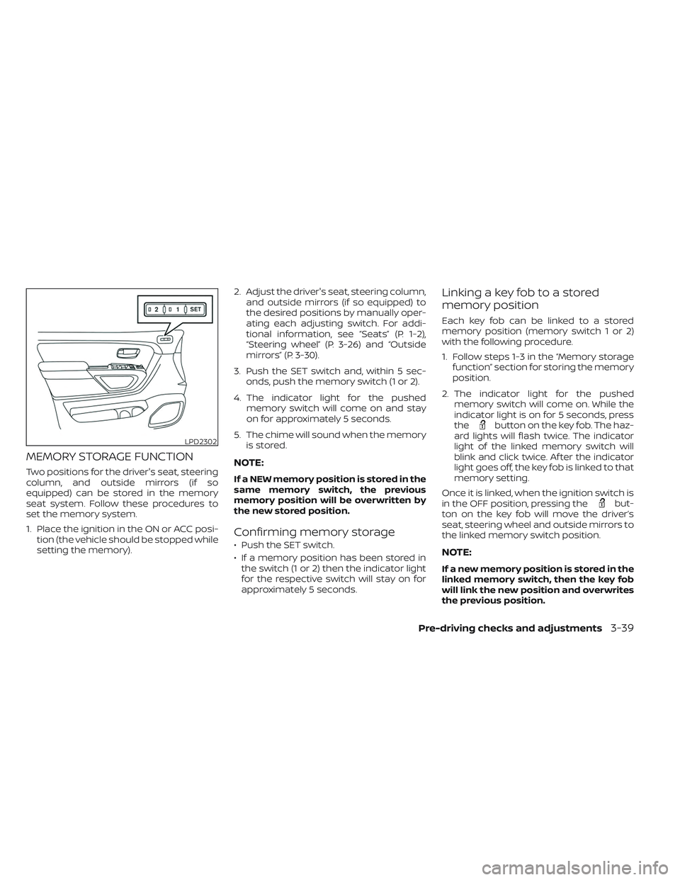
Two positions for the driver's seat, steering
column, and outside mirrors (if so
equipped) can be stored in the memory
seat system. Follow these procedures to
set the memory system.
1. Place the ignition in the ON or ACC posi-tion (the vehicle should be stopped while
setting the memory). 2. Adjust the driver's seat, steering column,
and outside mirrors (if so equipped) to
the desired positions by manually oper-
ating each adjusting switch. For addi-
tional information, see “Seats” (P. 1-2),
“Steering wheel” (P. 3-26) and “Outside
mirrors” (P. 3-30).
3. Push the SET switch and, within 5 sec- onds, push the memory switch (1 or 2).
4. The indicator light for the pushed memory switch will come on and stay
on for approximately 5 seconds.
5. The chime will sound when the memory is stored.NOTE:
If a NEW memory position is stored in the
same memory switch, the previous
memory position will be overwritten by
the new stored position.
Confirming memory storage
• Push the SET switch.
• If a memory position has been stored inthe switch (1 or 2) then the indicator light
for the respective switch will stay on for
approximately 5 seconds.
Linking a key fob to a stored
memory position
Each key fob can be linked to a stored
memory position (memory switch 1 or 2)
with the following procedure.
1. Follow steps 1-3 in the “Memory storage function” section for storing the memory
position.
2. The indicator light for the pushed memory switch will come on. While the
indicator light is on for 5 seconds, press
the
button on the key fob. The haz-
ard lights will flash twice. The indicator
light of the linked memory switch will
blink and click twice. Af ter the indicator
light goes off, the key fob is linked to that
memory setting.
Once it is linked, when the ignition switch is
in the OFF position, pressing the
but-
ton on the key fob will move the driver’s
seat, steering wheel and outside mirrors to
the linked memory switch position.
NOTE:
If a new memory position is stored in the
linked memory switch, then the key fob
will link the new position and overwrites
the previous position.
LPD2302
Pre-driving checks and adjustments3-39
Page 263 of 635
•Do not strike the cameras. They are
precision instruments. Doing so
could cause a malfunction or cause
damage resulting in a fire or an elec-
tric shock.
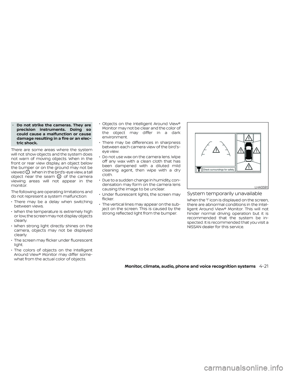
There are some areas where the system
will not show objects and the system does
not warn of moving objects. When in the
front or rear view display, an object below
the bumper or on the ground may not be
viewed
O1. When in the bird’s-eye view, a tall
object near the seam
O2of the camera
viewing areas will not appear in the
monitor.
The following are operating limitations and
do not represent a system malfunction:
• There may be a delay when switching between views.
• When the temperature is extremely high or low, the screen may not display objects
clearly.
• When strong light directly shines on the camera, objects may not be displayed
clearly.
• The screen may flicker under fluorescent light.
• The colors of objects on the Intelligent Around View® Monitor may differ some-
what from the actual color of objects. • Objects on the Intelligent Around View®
Monitor may not be clear and the color of
the object may differ in a dark
environment.
• There may be differences in sharpness between each camera view of the bird's-
eye view.
• Do not use wax on the camera lens. Wipe off any wax with a clean cloth that has
been dampened with a diluted mild
cleaning agent, then wipe with a dry
cloth.
• Due to a sudden change in humidity, con- densation may form on the camera lens
causing the image to be unclear.
• Under fluorescent lights, the screen may flicker.
• The vertical lines may appear on the sub- ject on the screen. This is caused by the
strong reflected light from the bumper.
System temporarily unavailable
When the “!” icon is displayed on the screen,
there are abnormal conditions in the Intel-
ligent Around View® Monitor. This will not
hinder normal driving operation but it is
recommended that the system be in-
spected. It is recommended that you visit a
NISSAN dealer for this service.
LHA3591
Monitor, climate, audio, phone and voice recognition systems4-21
Page 282 of 635
• for maximum cooling when using the airconditioning system.
Press the AUTO button to return to auto-
matic mode.
The air recirculation button will not be acti-
vated when the air conditioner is in
mode.
When the outside temperature exceeds
approximately 70°F (21°C), the air condition-
ing system may default to air recirculation
mode automatically to reduce overall
power consumption. To exit air recircula-
tion mode, select the fresh air intake but-
ton to enter fresh air mode.
In Floor/Defrost mode, the recirculation
button can be selected to block outside
odors. However, for maximum defogging in
this mode, it is recommended to turn recir-
culation off when possible.
Fresh air intake
Press thefresh air intake button to
draw outside air into the passenger
compartment.
Automatic intake air control
In the AUTO mode, the intake air will be
controlled automatically. When the outside
temperature exceeds approximately 70°F
(21°C), the air conditioning system may de-
fault to air recirculation mode automati-
cally to reduce overall power consumption.
To exit air recirculation mode, select the
fresh air intake button to enter fresh air
mode. The air recirculation indicator will
turn off, the fresh air indicator will turn on.
To manually control the intake air, press the
fresh air intake button. To return to the
automatic control mode if thefresh
air indicator is illuminated, press and hold
the
fresh air intake button for about 2
seconds. The fresh air indicator and air re-
circulation indicator lights will flash twice,
and then the intake air will be controlled
automatically. To return to the automatic
control mode if the
air recirculation
icon is illuminated, press and hold the
air recirculation button for about 2 sec-
onds. Theair recirculation indicator
andfresh air intake indicator lights will
flash twice and the intake air will be con-
trolled automatically. When OFF is selected,
the intake door is automatically forced to
recirculate. To get fresh air in OFF mode,
select the
fresh air intake button. The MODE can be changed in OFF mode to
direct the flow of incoming air if intake is set
to
fresh.
A/C (air conditioner) button
Start the engine, turn thefan speed
control buttons to the desired position and
press the
button to turn on the air
conditioner. To turn off the air conditioner,
press the
button again. In auto
mode, the air conditioner will be on even if
the
button indicator is off at tem-
peratures approximately at or above
freezing.
The air conditioner cooling function op-
erates only when the engine is running.
Air flow control
Press the MODE button to manually control
air flow and select the air outlet.
— Air flows from center and side
vents.
— Air flows from center and sidevents and foot outlets.
— Air flows mainly from foot outlets.— Air flows from defroster and footoutlets.
4-40Monitor, climate, audio, phone and voice recognition systems