2022 NISSAN TITAN radio
[x] Cancel search: radioPage 125 of 635

When the low tire pressure warning light
illuminates, you should stop and adjust
the tire pressure of all four tires to the
recommended COLD tire pressure shown
on the Tire and Loading Information la-
bel located in the driver's door opening.
The low tire pressure warning light does
not automatically turn off when the tire
pressure is adjusted. Af ter the tire is in-
flated to the recommended pressure,
the vehicle must be driven at speeds
above 16 mph (25 km/h) to activate the
TPMS and turn off the low tire pressure
warning light. Use a tire pressure gauge
to check the tire pressure.
The “Tire Pressure Low - Add Air” warning
appears each time the ignition switch is
placed in the ON position as long as the low
tire pressure warning light remains
illuminated.
For additional information, see “Vehicle in-
formation display” (P. 2-23), “Tire Pressure
Monitoring System (TPMS)” (P. 5-5) or (P. 6-3).
TPMS malfunction
If the TPMS is not functioning properly, the
low tire pressure warning light will flash for
approximately 1 minute when the ignition
switch is placed in the ON position. The
light will remain on af ter 1 minute. Have thesystem checked. It is recommended that
you visit a NISSAN dealer for this service.
The "Tire Pressure Low — Add Air" warning
does not appear if the low tire pressure
warning light illuminates to indicate a
TPMS malfunction.
For additional information, see “Tire Pres-
sure Monitoring System (TPMS)” (P. 5-5) and
“Tire pressure” (P. 8-33).
WARNING
• Radio waves could adversely affect
electric medical equipment. Those
who use a pacemaker should contact
the electric medical equipment
manufacturer for the possible influ-
ences before use.
• If the light does not illuminate with
the ignition switch placed in the ON
position, have the vehicle checked as
soon as possible. It is recommended
that you visit a NISSAN dealer for this
service. •
If the light illuminates while driving,
avoid sudden steering maneuvers or
abrupt braking, reduce vehicle
speed, pull off the road to a safe loca-
tion and stop the vehicle as soon as
possible. Driving with under-inflated
tires may permanently damage the
tires and increase the likelihood of
tire failure. Serious vehicle damage
could occur and may lead to an acci-
dent and could result in serious per-
sonal injury or death. Check the tire
pressure for all four tires. Adjust the
tire pressure to the recommended
COLD tire pressure show on the Tire
and Loading Information label lo-
cated in the driver’s door opening to
turn the low tire pressure warning
light off. If the light still illuminates
while driving af ter adjusting the tire
pressure, a tire may be flat or the
TPMS may be malfunctioning. If you
have a flat tire, replace it with a spare
tire as soon as possible. If no tire is
flat and all tires are properly inflated,
have the vehicle checked. It is recom-
mended that you visit a NISSAN
dealer for this service.
Instruments and controls2-19
Page 196 of 635

PERSONAL LIGHTS (if so equipped)
To turn the rear personal lights on, push the
switch. To turn them off, push the switch
again.The HomeLink® Universal Transceiver pro-
vides a convenient way to consolidate the
functions of up to three individual hand-
held transmitters into one built-in device.
HomeLink® Universal Transceiver:
• Will operate most radio frequency de-
vices such as garage doors, gates, home
and office lighting, entry door locks and
security systems.
• Is powered by your vehicle's battery. No separate batteries are required. If the ve-
hicle's battery is discharged or is discon-
nected, HomeLink® will retain all
programming.
When the HomeLink® Universal Trans-
ceiver is programmed, retain the original
transmitter for future programming pro-
cedures (Example: new vehicle pur-
chases). Upon sale of the vehicle, the
programmed HomeLink® Universal
Transceiver buttons should be erased for
security purposes. For additional infor-
mation, see “Programming HomeLink®”
(P. 2-91).
WARNING
• Your vehicle's engine should be
turned off while programming the
HomeLink® Universal Transceiver. For
additional information, see “Push-
button ignition switch” (P. 5-13). Do
not breathe exhaust gases; they con-
tain colorless and odorless carbon
monoxide. Carbon monoxide is dan-
gerous. It can cause unconscious-
ness or death.
• Do not use the HomeLink® Universal
Transceiver with any garage door
opener that lacks safety stop and re-
verse features as required by federal
safety standards. (These standards
became effective for opener models
manufactured af ter April 1, 1982.) A
garage door opener which cannot
detect an object in the path of a clos-
ing garage door and then automati-
cally stop and reverse does not meet
current federal safety standards. Us-
ing a garage door opener without
these features increases the risk of
serious injury or death.
LIC3907
HOMELINK® UNIVERSAL
TRANSCEIVER (if so equipped)
2-90Instruments and controls
Page 197 of 635

•During the programming procedure
your garage door or security gate will
open and close (if the transmitter is
within range). Make sure that people
or objects are clear of the garage
door, gate, etc., that you are
programming.
PROGRAMMING HOMELINK®
If you have any questions or are having
difficulty programming your HomeLink®
buttons, refer to the HomeLink® web site at:
www.homelink.com or call 1-800-355-3515.
NOTE:
Place the ignition switch in the ON or ACC
position (without starting the engine)
when programming HomeLink®. It is also
recommended that a new battery be
placed in the hand-held transmitter of
the device being programmed to
HomeLink® for quicker programming
and accurate transmission of the radio
frequency. 1. Position the end of your hand-held
transmitter 1–3 in (2–8 cm) away from
the HomeLink® surface, keeping the
HomeLink® indicator light
O1in view. 2. Using both hands, simultaneously press
and hold the desired HomeLink® button
and hand-held transmitter button. DO
NOT release until the HomeLink® indica-
tor light
O1flashes slowly and then rap-
idly. When the indicator light flashes rap-
idly, both buttons may be released. (The
rapid flashing indicates successful
programming.)
NOTE:
Some devices may require you to replace
Step 2 with the cycling procedure noted
in “Programming HomeLink® for gate
openers” (P. 2-92).
LIC2365LIC4095
Instruments and controls2-91
Page 209 of 635

CHILD SAFETY REAR DOOR LOCK
(if so equipped)
Child safety locks help prevent the rear
doors from being opened accidentally, espe-
cially when small children are in the vehicle.
The child safety lock levers are located on
the edge of the rear doors.
When the lever is in the unlock position
O1,
the door can be opened from the outside
or the inside.
When the lever is in the LOCK position
O2,
the door can be opened only from the
outside.
WARNING
• Radio waves could adversely affect
electric medical equipment. Those
who use a pacemaker should contact
the electric medical equipment
manufacturer for the possible influ-
ences before use.
• The Intelligent Key transmits radio
waves when the buttons are pressed.
The FAA advises the radio waves may
affect aircraf t navigation and com-
munication systems. Do not operate
the Intelligent Key while on an air-
plane. Make sure the buttons are not
operated unintentionally when the
unit is stored for a flight.
• Never leave the Intelligent Key in the
vehicle when you leave the vehicle.
The Intelligent Key system can operate all
the door locks using the remote control
function or pushing the request switch (if
so equipped) on the vehicle without taking
the key out from a pocket or purse. The
operating environment and/or conditions
may affect the Intelligent Key system
operation.
Be sure to read the following before using
the Intelligent Key system.CAUTION
Be sure to carry the Intelligent Key with
you when operating the vehicle.
The Intelligent Key is capable of receiving
and transmitting radio waves. The Intelli-
gent Key system transmits weak radio
waves from various distances. Environ-
mental conditions may interfere with the
operation of the Intelligent Key system un-
der the following operating conditions:
• When operating near a location where strong radio waves are transmitted, such
as a TV tower, power station and broad-
casting station.
• When in possession of wireless equip- ment, such as a cellular telephone, trans-
ceiver, or a CB radio.
• When the Intelligent Key is in contact with or covered by metallic materials.
• When any type of radio wave remote con- trol is used nearby.
• When the Intelligent Key is placed near an electric appliance such as a personal
computer.
• When the vehicle is parked near a parking meter.
LPD3096
NISSAN INTELLIGENT KEY® SYSTEM
Pre-driving checks and adjustments3-9
Page 210 of 635

In such cases, correct the operating condi-
tions before using the Intelligent Key func-
tion or use the mechanical key.
Although the life of the battery varies de-
pending on the operating conditions, the
battery’s life is approximately two years. If
the battery is discharged, replace it with a
new one.
When the Intelligent Key battery is low the
“Key ID Incorrect” warning appears in the
vehicle information display. When the Intel-
ligent Key battery is low the “Key Battery
Low” indicator appears. For additional in-
formation, see “Vehicle information display
warnings and indicators” (P. 2-32).
Since the Intelligent Key is capable of re-
ceiving radio waves, if the key is lef t near
equipment which transmits strong radio
waves, such as signals from a TV and per-
sonal computer, the battery life may be-
come shorter.
For additional information, see “Battery re-
placement” (P. 8-27).
As many as four Intelligent Keys can be
registered and used with one vehicle. For
information about the purchase and use of
additional Intelligent Keys, it is recom-
mended that you visit a NISSAN dealer.
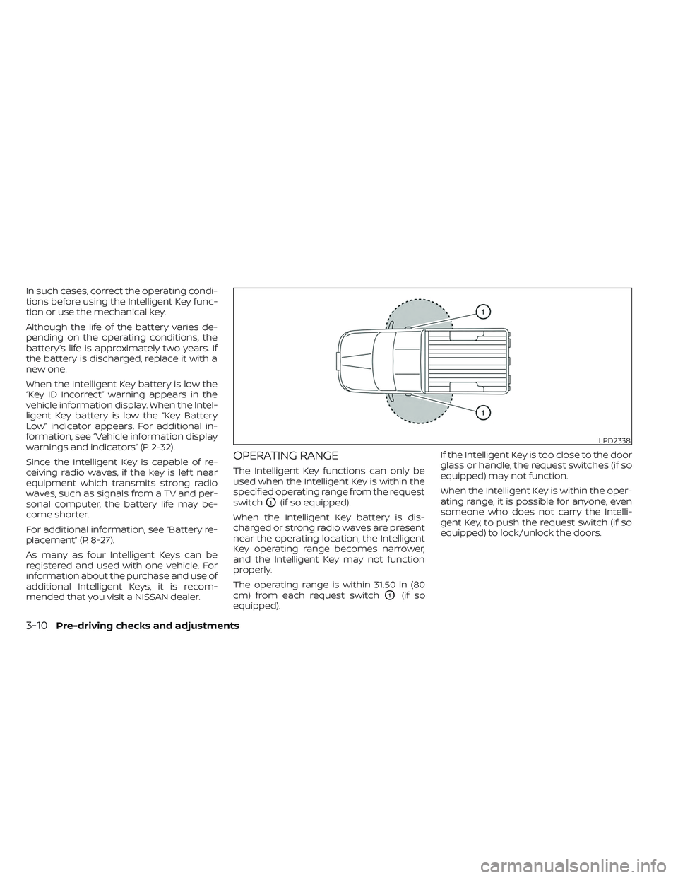
OPERATING RANGE
The Intelligent Key functions can only be
used when the Intelligent Key is within the
specified operating range from the request
switch
O1(if so equipped).
When the Intelligent Key battery is dis-
charged or strong radio waves are present
near the operating location, the Intelligent
Key operating range becomes narrower,
and the Intelligent Key may not function
properly.
The operating range is within 31.50 in (80
cm) from each request switch
O1(if so
equipped). If the Intelligent Key is too close to the door
glass or handle, the request switches (if so
equipped) may not function.
When the Intelligent Key is within the oper-
ating range, it is possible for anyone, even
someone who does not carry the Intelli-
gent Key, to push the request switch (if so
equipped) to lock/unlock the doors.
LPD2338
3-10Pre-driving checks and adjustments
Page 221 of 635

CAUTION
When the Intelligent Key battery is dis-
charged or other strong radio wave
sources are present near the operating
location, the Intelligent Key operating
range becomes narrower, and the Intel-
ligent Key may not function properly.
The Remote Engine Start function can only
be used when the Intelligent Key is within
the specified operating range from the
vehicle.
The Remote Engine Start operating range
is approximately 197 f t (60 m) from the
vehicle.
REMOTE STARTING THE VEHICLE
To use the Remote Engine Start feature to
start the engine perform the following:
1. Aim the Intelligent Key at the vehicle.
2. Press the
button to lock all doors.
3. Within 5 seconds press and hold the
button until the turn signal lights
flash and the tail lamps turn on. If the
vehicle is not within view press and hold
the
button for at least 2 seconds. The following events will occur when the
engine starts:
• The parking lights will turn on and remain
on as long as the engine is running.
• The doors will be locked and the climate control system may come on.
• The engine will continue to run for 10 min- utes. Repeat the steps to extend the time
for an additional 10 minutes. For addi-
tional information, see “Extending engine
run time” (P. 3-21).
Press and hold the brake then push the
push-button ignition switch to the ON po-
sition before driving. For additional infor-
mation, see “Driving the vehicle” (P. 5-18)).
EXTENDING ENGINE RUN TIME
The Remote Engine Start feature can be
extended one time by performing the
steps listed in “Remote starting the vehicle”
in this section. Run time will be calculated
as follows:
• The first 10 minute run time will start when the Remote Engine Start function is
performed. • The second 10 minutes will start immedi-
ately when the Remote Engine Start
function is performed again. For example,
if the engine has been running for 5 min-
utes, and 10 minutes are added, the en-
gine will run for a total of 15 minutes.
• Extending engine run time will count to- wards the two Remote Engine Start limit.
A maximum of two Remote Engine Starts,
or a single Remote Engine Start with an
extension, are allowed between ignition
cycles. The ignition switch must be cycled
to the ON position and then back to the
OFF position before the Remote Engine
Start procedure can be used again.
CANCELING A REMOTE ENGINE
START
To cancel a Remote Engine Start, perform
one of the following:
• Aim the Intelligent Key at the vehicle and press
until the parking lights turn off.
• Turn on the hazard warning flashers.
• Cycle the ignition switch on and then off.
• The extended engine run time has expired.
• The first 10 minute timer has expired.
• The engine hood has been opened.
Pre-driving checks and adjustments3-21
Page 243 of 635

Remote control buttons.....................4-50
Wireless headphone operation ..............4-51
General operation ........................... 4-52
Video operation ............................. 4-54
HDMI/MHL connection ......................4-55
USB/SD card operation ......................4-56
Slingplayer® ................................. 4-62
Miracast® ................................... 4-64
Using the mobile application on your
mobile device ............................... 4-65SmartStream
............................... 4-66
Settings ..................................... 4-68
Troubleshooting ............................ 4-76
Specifications ............................... 4-78
Compliance information ....................4-79
Car phone or CB radio .......................... 4-82
iPod®/iPhone® ................................. 4-83
Page 246 of 635

•The distance guide line and the ve-
hicle width line should be used as a
reference only when the vehicle is on
a level paved surface. The distance
viewed on the monitor is for refer-
ence only and may be different than
the actual distance between the ve-
hicle and displayed objects.
CAUTION
Do not scratch the camera lens when
cleaning dirt or snow from the front of
the camera.
The RearView Monitor system automati-
cally shows a rear view of the vehicle when
the shif t lever is shif ted into the R (Reverse)
position. While in R (Reverse), pressing the
CAMERA will cycle through guideline op-
tions. The radio can still be heard while the
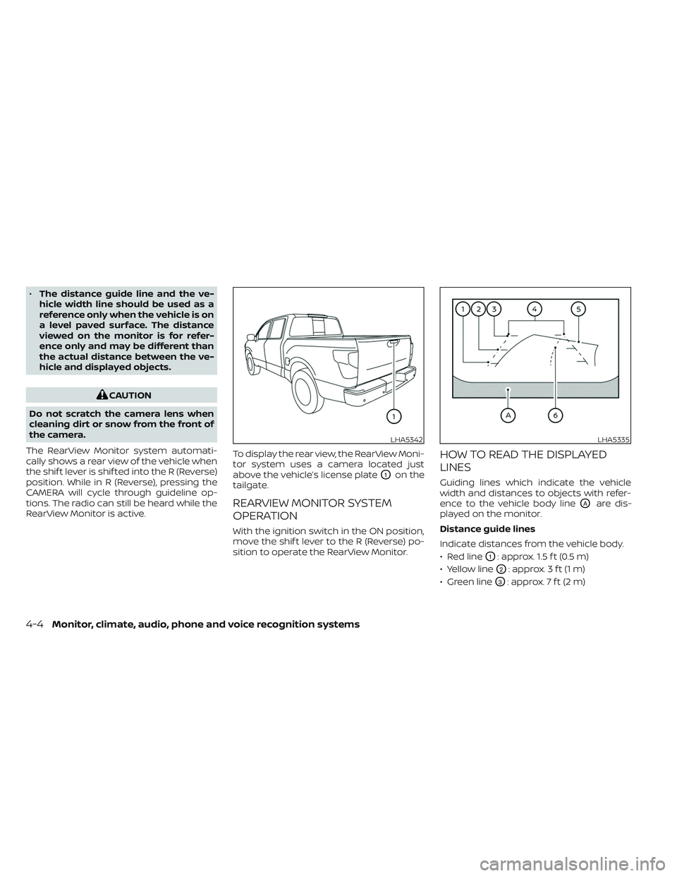
RearView Monitor is active. To display the rear view, the RearView Moni-
tor system uses a camera located just
above the vehicle’s license plate
O1on the
tailgate.
REARVIEW MONITOR SYSTEM
OPERATION
With the ignition switch in the ON position,
move the shif t lever to the R (Reverse) po-
sition to operate the RearView Monitor.
HOW TO READ THE DISPLAYED
LINES
Guiding lines which indicate the vehicle
width and distances to objects with refer-
ence to the vehicle body line
OAare dis-
played on the monitor.
Distance guide lines
Indicate distances from the vehicle body.
• Red line
O1: approx. 1.5 f t (0.5 m)
• Yellow line
O2: approx. 3 f t (1 m)
• Green line
O3: approx. 7 f t (2 m)
LHA5342LHA5335
4-4Monitor, climate, audio, phone and voice recognition systems