2022 NISSAN TITAN weight
[x] Cancel search: weightPage 87 of 635

NOTE:
A system check will be performed during
which the front passenger air bag status
light will remain lit for about 7 seconds
initially.
If the light is still ON af ter this, the person
should be advised not to ride in the front
passenger seat and the vehicle should be
checked as soon as possible. It is recom-
mended that you visit a NISSAN dealer for
this service.
Other supplemental front-impact air
bag precautions
WARNING
• Do not place any objects on the
steering wheel pad or on the instru-
ment panel. Also, do not place any
objects between any occupant and
the steering wheel or instrument
panel. Such objects may become
dangerous projectiles and cause in-
jury if the front air bags inflate.
• Immediately af ter inflation, several
front air bag system components will
be hot. Do not touch them; you may
severely burn yourself. •
No unauthorized changes should be
made to any components or wiring
of the supplemental air bag system.
This is to prevent accidental inflation
of the supplemental air bag or dam-
age to the supplemental air bag
system.
• Do not make unauthorized changes
to your vehicle's electrical system,
suspension system or front end
structure. This could affect proper
operation of the front air bag system.
• Tampering with the front air bag sys-
tem may result in serious personal
injury. Tampering includes changes
to the steering wheel and the instru-
ment panel assembly by placing ma-
terial over the steering wheel pad
and above the instrument panel or
by installing additional trim material
around the air bag system.
• Removing or modif ying the front
passenger seat may affect the func-
tion of the air bag system and result
in serious personal injury. •
Modif ying or tampering with the
front passenger seat may result in
serious personal injury. For example,
do not change the front seats by
placing material on the seat cushion
or by installing additional trim mate-
rial, such as seat covers, on the seat
that are not specifically designed to
assure proper air bag operation. Ad-
ditionally, do not stow any objects
under the front passenger seat or the
seat cushion and seatback. Such ob-
jects may interfere with the proper
operation of the occupant classifica-
tion sensor (weight sensor).
• No unauthorized changes should be
made to any components or wiring
of the seat belt system. This may af-
fect the front air bag system. Tam-
pering with the seat belt system may
result in serious personal injury.
Safety-Seats, seat belts and supplemental restraint system1-67
Page 105 of 635

•If there is an impact to your vehicle
from any direction, your Occupant
Classification Sensor (OCS) (if so
equipped) should be checked to
verif y it is still functioning correctly. It
is recommended that you visit a
NISSAN dealer for this service. The
OCS (weight sensor) (if so equipped)
should be checked even if no air bags
deploy as a result of the impact. Fail-
ure to verif y proper OCS (weight sen-
sor) (if so equipped) function may re-
sult in an improper air bag
deployment resulting in injury or
death.
Safety-Seats, seat belts and supplemental restraint system1-85
Page 115 of 635

FUEL GAUGE
The gauge indicates theapproximatefuel
level in the tank.
The gauge may move slightly during brak-
ing, turning, acceleration, or going up or
down hills.
The gauge needle returns to 0 (Empty) af-
ter the ignition switch is placed in the OFF
position.
The low fuel warning light comes on when
the amount of fuel in the tank is getting low.
Refill the fuel tank before the gauge reg-
isters 0 (Empty). The
indicates that the fuel-filler door
is located on the driver's side of the vehicle.
CAUTION
• If the vehicle runs out of fuel, the
Malfunction Indicator Light (MIL) may
come on. Refuel as soon as possible.
Af ter a few driving trips. the
light
should turn off. If the light remains on
af ter a few driving trips, have the ve-
hicle inspected. It is recommended
that you visit a NISSAN dealer for this
service.
• For additional information, see “Mal-
function Indicator Light (MIL)”
(P. 2-15).
DISTANCE TO EMPTY (DTE)
Displays the estimated distance the ve-
hicle can be driven before refueling. The
value is calculated based on recent fuel
economy, the amount of fuel remaining in
the fuel tank, and the actual fuel
consumption.
Changes in driving patterns or conditions
can cause the DTE value to vary. As a result,
the value displayed may differ from the ac-
tual distance that can be driven. DTE display will change to “---” when the
fuel level in the tank is getting low, prior to
the fuel gauge reaching 0 (Empty).
NOTE:
• The DTE value af ter refill is estimated
based on recent fuel economy and
amount of fuel added.
• If a small amount of fuel is added, or the ignition is on during refueling, the
display may not be updated.
• Conditions that affect the fuel economy will also affect the estimated
DTE value (city/highway driving, idle
time, remote start time, terrain, sea-
sonal weather, added vehicle weight,
added deflectors, roof racks, etc.).
LIC2222
Instruments and controls2-9
Page 178 of 635

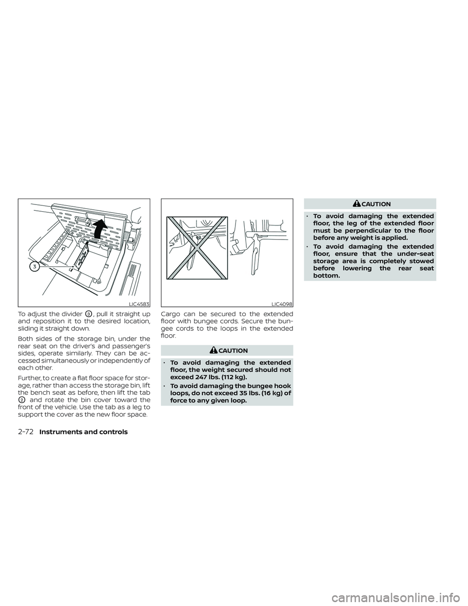
To adjust the dividerO3, pull it straight up
and reposition it to the desired location,
sliding it straight down.
Both sides of the storage bin, under the
rear seat on the driver’s and passenger’s
sides, operate similarly. They can be ac-
cessed simultaneously or independently of
each other.
Further, to create a flat floor space for stor-
age, rather than access the storage bin, lif t
the bench seat as before, then lif t the tab
O2and rotate the bin cover toward the
front of the vehicle. Use the tab as a leg to
support the cover as the new floor space. Cargo can be secured to the extended
floor with bungee cords. Secure the bun-
gee cords to the loops in the extended
floor.
CAUTION
• To avoid damaging the extended
floor, the weight secured should not
exceed 247 lbs. (112 kg).
• To avoid damaging the bungee hook
loops, do not exceed 35 lbs. (16 kg) of
force to any given loop.
CAUTION
• To avoid damaging the extended
floor, the leg of the extended floor
must be perpendicular to the floor
before any weight is applied.
• To avoid damaging the extended
floor, ensure that the under-seat
storage area is completely stowed
before lowering the rear seat
bottom.
LIC4583LIC4098
2-72Instruments and controls
Page 238 of 635

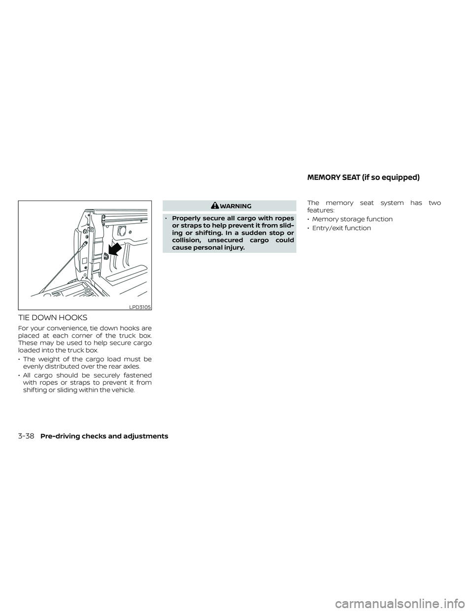
TIE DOWN HOOKS
For your convenience, tie down hooks are
placed at each corner of the truck box.
These may be used to help secure cargo
loaded into the truck box.
• The weight of the cargo load must beevenly distributed over the rear axles.
• All cargo should be securely fastened with ropes or straps to prevent it from
shif ting or sliding within the vehicle.
WARNING
• Properly secure all cargo with ropes
or straps to help prevent it from slid-
ing or shif ting. In a sudden stop or
collision, unsecured cargo could
cause personal injury. The memory seat system has two
features:
• Memory storage function
• Entry/exit function
LPD3105
MEMORY SEAT (if so equipped)
3-38Pre-driving checks and adjustments
Page 514 of 635

Information label under the “Cold
Tire Pressure” heading. The Tire and
Loading Information label is affixed
to the driver side center pillar. Tire
pressures should be checked regu-
larly because:
• Most tires naturally lose air overtime.
• Tires can lose air suddenly when driven over potholes or other ob-
jects or if the vehicle strikes a curb
while parking.
The tire pressures should be
checked when the tires are cold. The
tires are considered COLD af ter the
vehicle has been parked for 3 or
more hours, or driven less than 1 mile
(1.6 km) at moderate speeds.
The TPMS with Easy-Fill Tire Alert
provides visual and audible signals
outside the vehicle for inflating tires
to the recommended COLD tire pressure. For additional information,
see “TPMS with Easy-Fill Tire Alert”
(P. 5-8).
Incorrect tire pressure, including under
inflation, may adversely affect tire life
and vehicle handling.
WARNING
•
Improperly inflated tires can
fail suddenly and cause an
accident.
•The Gross Vehicle Weight Rat-
ing (GVWR) is located on the
F.M.V.S.S. certification label. The
vehicle weight capacity is indi-
cated on the Tire and Loading
Information label. Do not load
your vehicle beyond this capac-
ity. Overloading your vehicle
may result in reduced tire life,
unsafe operating conditions
due to premature tire failure, or
unfavorable handling charac-
teristics and could also lead to a
serious accident. Loading be- yond the specified capacity
may also result in failure of
other vehicle components.
•Before taking a long trip, or
whenever you heavily load your
vehicle, use a tire pressure
gauge to ensure that the tire
pressures are at the specified
level.
•For additional information re-
garding tires, refer to “Impor-
tant Tire Safety Information”
(US) or “Tire Safety Information”
(Canada) in the Warranty Infor-
mation Booklet.
8-34
Do-it-yourself
Page 518 of 635

O1Tire size (example: P215/65R15 95H)
1. P: The “P” indicates the tire is de-signed for passenger vehicles (not
all tires have this information).
2. Three-digit number (215): This number gives the width in milli-
meters of the tire from sidewall
edge to sidewall edge. 3. Two-digit number (65): This num-
ber, known as the aspect ratio,
gives the tire's ratio of height to
width.
4. R: The “R” stands for radial.
5. Two-digit number (15): This num- ber is the wheel or rim diameter in
inches. 6. Two- or three-digit number (95):
This number is the tire's load
index. It is a measurement of how
much weight each tire can
support.
7. H: Tire speed rating. You should not drive the vehicle faster than
the tire speed rating.
WDI0395
Example
8-38Do-it-yourself
Page 562 of 635

10 Technical and consumer information
Recommended fluids/lubricants and
capacities...................................... 10-2
Fuel recommendation ......................10-4
Engine oil and oil filter
recommendations .......................... 10-7
Air conditioner system refrigerant and
oil recommendations .......................10-8
Specifications .................................. 10-9
Engine ...................................... 10-9
Wheels and tires ........................... 10-10
Dimensions and weights ....................10-11
When traveling or registering in another
country ....................................... 10-15
Vehicle identification .......................... 10-15
Vehicle Identification Number (VIN)
plate ....................................... 10-15
Vehicle identification number
(chassis number) ........................... 10-15
Engine serial number ......................10-16
F.M.V.S.S. certification label ..................10-16
Emission control information label .........10-17
Tire and Loading Information label .........10-17
Air conditioner specification label ..........10-18
Installing front license plate ...................10-19
Vehicle loading information ...................10-20Terms
...................................... 10-21
Vehicle load capacity ....................... 10-21
Securing the load .......................... 10-23
Utili-track® channel system
(if so equipped) ............................. 10-24
Rear assist step (if so equipped) ............10-28
Loading tips ................................ 10-29
Measurement of weights ...................10-29
Truck-camper loading information ............10-30
Crew cab models .......................... 10-30
King Cab® models .......................... 10-30
Special Body vehicles ......................10-30
Location for center of gravity ...............10-30
Vehicle load weight capacity ...............10-31
Measurement of weights ...................10-31
Towing a trailer ................................ 10-32
Maximum
load limits....................... 10-32
Towing load/specification ..................10-36
Towing safety .............................. 10-37
Flat towing for 2-Wheel Drive (2WD)
vehicle (if so equipped) .....................10-54
Flat towing for 4-Wheel Drive (4WD)
vehicle (if so equipped) .....................10-54
Snowplow .................................... 10-55
Uniform tire quality grading ...................10-55