2022 NISSAN TITAN clock
[x] Cancel search: clockPage 225 of 635

–Keep the pump nozzle in contact
with the container while you are
filling it.
– Use only approved portable fuel
containers for flammable liquid.
CAUTION
• Do not use E-15 or E-85 fuel in your
vehicle. For additional information,
see “Fuel recommendation” (P. 10-4).
• The Loose Fuel Cap warning mes-
sage will appear if the fuel-filler cap
is not properly tightened. It may take
a few driving trips for the message to
be displayed. Failure to tighten the
fuel-filler cap properly af ter the
Loose Fuel Cap warning message ap-
pears may cause the
Malfunc-
tion Indicator Light (MIL) to
illuminate. •
Failure to tighten the fuel-filler cap
properly may cause the
Mal-
function Indicator Light (MIL) to illu-
minate. If the
light illuminates
because the fuel-filler cap is loose or
missing, tighten or install the cap and
continue to drive the vehicle. The
light should turn off af ter a few
driving trips. If thelight does not
turn off af ter a few driving trips, have
the vehicle inspected. It is recom-
mended that you visit a NISSAN
dealer for this service.
• For additional information, see “Mal-
function Indicator Light (MIL)”
(P. 2-15).
• If fuel is spilled on the vehicle body,
flush it away with water to avoid
paint damage. To remove the fuel-filler cap:
1. Turn the fuel-filler cap counterclockwise
to remove.
2. Loop the tether strap around the hook while refueling.
To install the fuel-filler cap:
1. Insert the fuel-filler cap straight into the fuel-filler tube.
2. Turn the fuel-filler cap clockwise until a single click is heard.
LPD3101
Pre-driving checks and adjustments3-25
Page 291 of 635
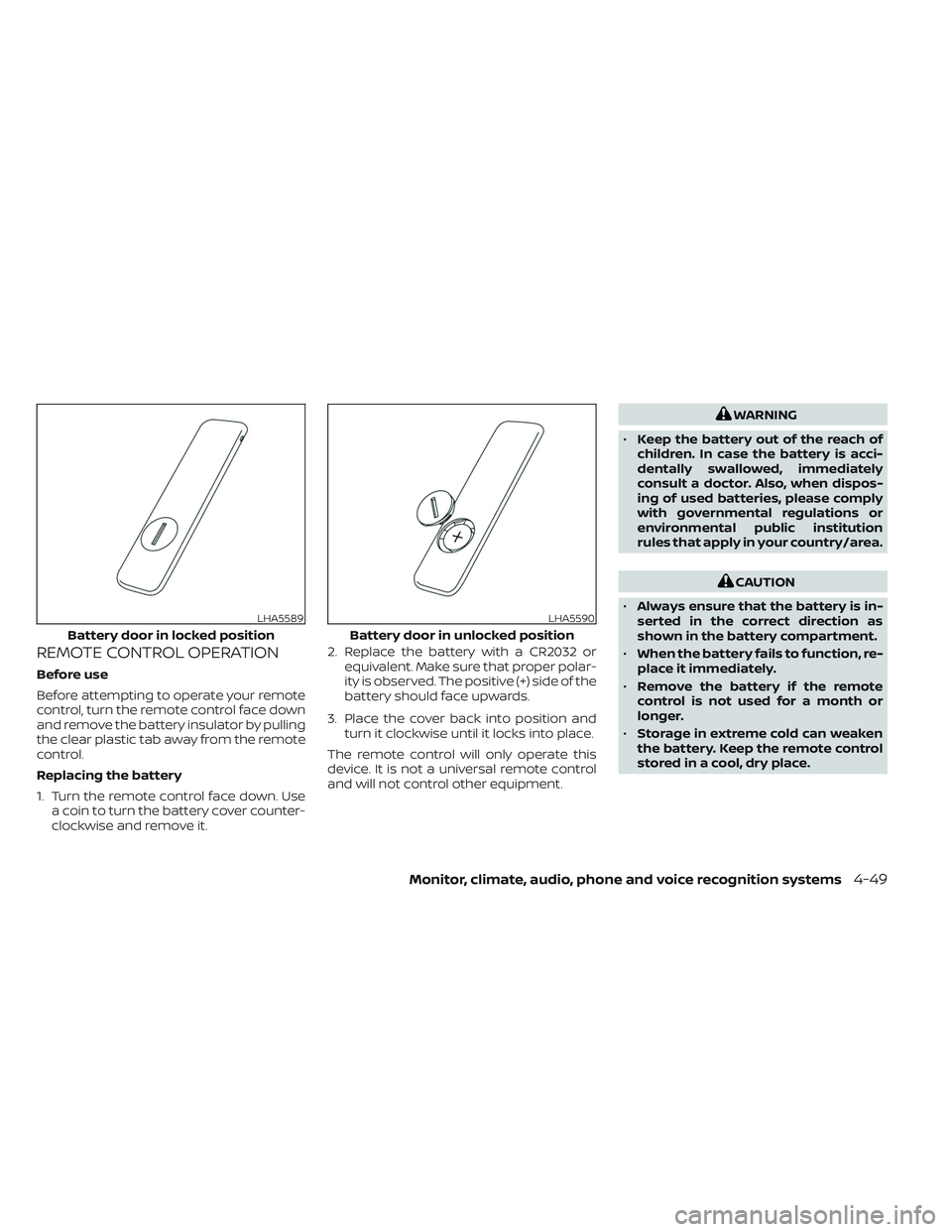
REMOTE CONTROL OPERATION
Before use
Before attempting to operate your remote
control, turn the remote control face down
and remove the battery insulator by pulling
the clear plastic tab away from the remote
control.
Replacing the battery
1. Turn the remote control face down. Usea coin to turn the battery cover counter-
clockwise and remove it. 2. Replace the battery with a CR2032 or
equivalent. Make sure that proper polar-
ity is observed. The positive (+) side of the
battery should face upwards.
3. Place the cover back into position and turn it clockwise until it locks into place.
The remote control will only operate this
device. It is not a universal remote control
and will not control other equipment.
WARNING
• Keep the battery out of the reach of
children. In case the battery is acci-
dentally swallowed, immediately
consult a doctor. Also, when dispos-
ing of used batteries, please comply
with governmental regulations or
environmental public institution
rules that apply in your country/area.
CAUTION
• Always ensure that the battery is in-
serted in the correct direction as
shown in the battery compartment.
• When the battery fails to function, re-
place it immediately.
• Remove the battery if the remote
control is not used for a month or
longer.
• Storage in extreme cold can weaken
the battery. Keep the remote control
stored in a cool, dry place.
LHA5589
Battery door in locked position
LHA5590
Battery door in unlocked position
Monitor, climate, audio, phone and voice recognition systems4-49
Page 461 of 635
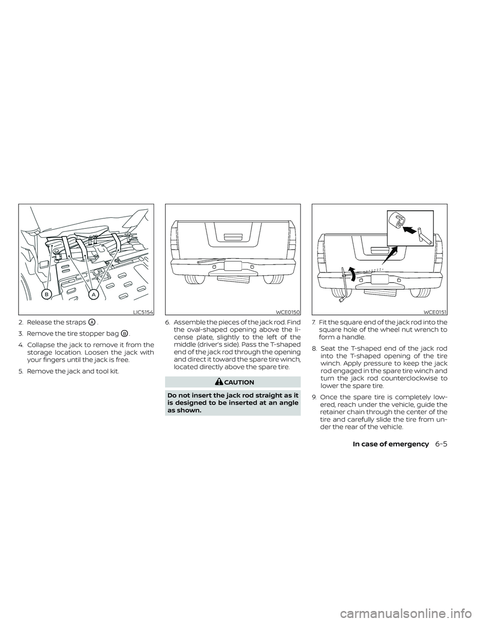
2. Release the strapsOA.
3. Remove the tire stopper bag
OB.
4. Collapse the jack to remove it from the storage location. Loosen the jack with
your fingers until the jack is free.
5. Remove the jack and tool kit. 6. Assemble the pieces of the jack rod. Find
the oval-shaped opening above the li-
cense plate, slightly to the lef t of the
middle (driver’s side). Pass the T-shaped
end of the jack rod through the opening
and direct it toward the spare tire winch,
located directly above the spare tire.
CAUTION
Do not insert the jack rod straight as it
is designed to be inserted at an angle
as shown. 7. Fit the square end of the jack rod into the
square hole of the wheel nut wrench to
form a handle.
8. Seat the T-shaped end of the jack rod into the T-shaped opening of the tire
winch. Apply pressure to keep the jack
rod engaged in the spare tire winch and
turn the jack rod counterclockwise to
lower the spare tire.
9. Once the spare tire is completely low- ered, reach under the vehicle, guide the
retainer chain through the center of the
tire and carefully slide the tire from un-
der the rear of the vehicle.
LIC5154WCE0150WCE0151
In case of emergency6-5
Page 462 of 635
10. Securely store the flat tire beneath thevehicle, from where the full size spare
was removed. To reinstall the wheel, re-
move the center cap (if so equipped)
and insert the retainer chain through
the wheel. Be sure the rubber rim cover
(if so equipped) is centered on the
wheel before lif ting. Use the assembled
jacking rod to slowly rotate the winch
clockwise to raise the wheel to the
vehicle.
11. To reinstall the jack and tool kit, reverse steps 1 through 5.
NOTE:
Inspect the rubber rim cover every six
years and replace as necessary. It is rec-
ommended that you visit a NISSAN
dealer for this service.
CAUTION
• Be sure to center the spare tire sus-
pending plate on the wheel and then
lif t the spare tire.
• Failure to use the rubber rim cover
may allow the chain to get stuck in
the wheel nut holes when stowed.
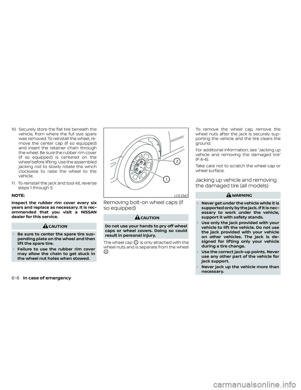
Removing bolt-on wheel caps (if
so equipped)
CAUTION
Do not use your hands to pry off wheel
caps or wheel covers. Doing so could
result in personal injury.
The wheel cap
O1is only attached with the
wheel nuts and is separate from the wheel
O2. To remove the wheel cap, remove the
wheel nuts af ter the jack is securely sup-
porting the vehicle and the tire clears the
ground.
For additional information, see “Jacking up
vehicle and removing the damaged tire”
(P. 6-6).
Take care not to scratch the wheel cap or
wheel surface.
Jacking up vehicle and removing
the damaged tire (all models)
WARNING
• Never get under the vehicle while it is
supported only by the jack. If it is nec-
essary to work under the vehicle,
support it with safety stands.
• Use only the jack provided with your
vehicle to lif t the vehicle. Do not use
the jack provided with your vehicle
on other vehicles. The jack is de-
signed for lif ting only your vehicle
during a tire change.
• Use the correct jack-up points. Never
use any other part of the vehicle for
jack support.
• Never jack up the vehicle more than
necessary.LCE2367
6-6In case of emergency
Page 464 of 635
Carefully read the caution label attached
to the jack body and the following in-
structions.
1. Loosen each wheel nut one or two turnsby turning counterclockwise with the
wheel nut wrench. Do not remove the
wheel nuts until the tire is off the
ground.
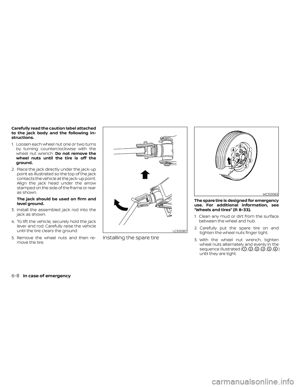
2. Place the jack directly under the jack-up point as illustrated so the top of the jack
contacts the vehicle at the jack-up point.
Align the jack head under the arrow
stamped on the side of the frame or rear
as shown.
The jack should be used on firm and
level ground.
3. Install the assembled jack rod into the jack as shown.
4. To lif t the vehicle, securely hold the jack lever and rod. Carefully raise the vehicle
until the tire clears the ground.
5. Remove the wheel nuts and then re- move the tire.
Installing the spare tire
The spare tire is designed for emergency
use. For additional information, see
“Wheels and tires” (P. 8-33).
1. Clean any mud or dirt from the surfacebetween the wheel and hub.
2. Carefully put the spare tire on and tighten the wheel nuts finger tight.
3. With the wheel nut wrench, tighten wheel nuts alternately and evenly in the
sequence illustrated (
O1,O2,O3,O4,O5,O6)
until they are tight.
LCE0087
WCE0063
6-8In case of emergency
Page 491 of 635
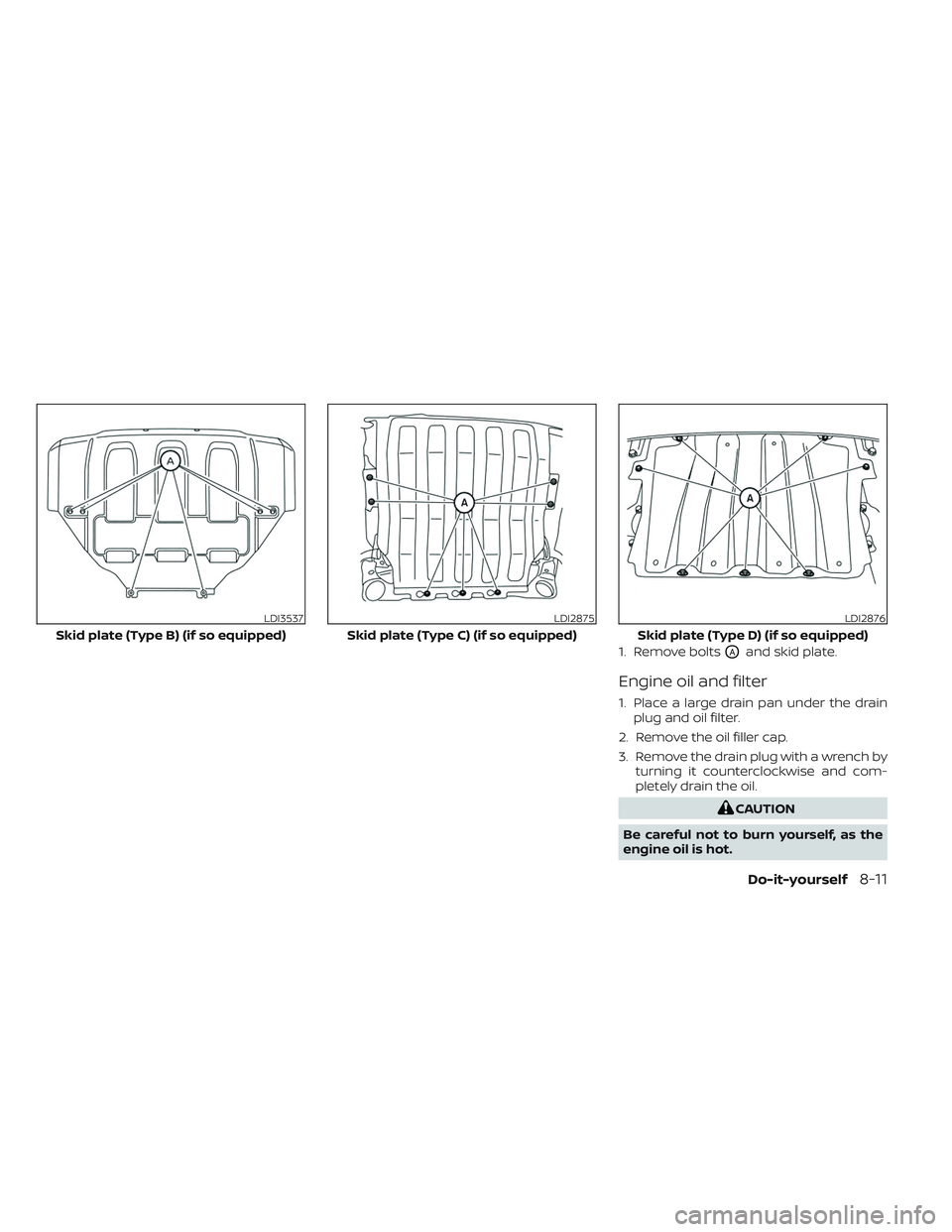
1. Remove boltsOAand skid plate.
Engine oil and filter
1. Place a large drain pan under the drainplug and oil filter.
2. Remove the oil filler cap.
3. Remove the drain plug with a wrench by turning it counterclockwise and com-
pletely drain the oil.
CAUTION
Be careful not to burn yourself, as the
engine oil is hot.
LDI3537
Skid plate (Type B) (if so equipped)
LDI2875
Skid plate (Type C) (if so equipped)
LDI2876
Skid plate (Type D) (if so equipped)
Do-it-yourself8-11
Page 492 of 635
WARNING
• Prolonged and repeated contact
with used engine oil may cause skin
cancer.
• Try to avoid direct skin contact with
used oil. If skin contact is made, wash
thoroughly with soap or hand
cleaner as soon as possible.
• Keep used engine oil out of reach of
children.
4. Loosen the oil filter with an oil filter wrench by turning it counterclockwise.
Remove the oil filter by turning it by
hand.
5. Wipe the engine oil filter mounting sur- face with a clean rag.
CAUTION
Be sure to remove any old gasket ma-
terial remaining on the sealing surface
of the engine. Failure to do so could
lead to an oil leak and engine damage.
• The dipstick must be inserted in
place to prevent oil spillage from the
dipstick hole when filling the engine
with oil. 6. Coat the gasket on the new filter with
clean engine oil.
7. Screw in the oil filter clockwise until a slight resistance is felt, then tighten addi-
tionally more than 2/3 turn.
Oil filter tightening torque: 11 to 15 f t-lb (15.0 to 21.0 N·m)
8. Clean and re-install the drain plug with a new washer. Securely tighten the drain
plug with a wrench. Do not use exces-
sive force.
Drain plug tightening torque: 22 to 29 f t-lb (29.4 to 39.2 N·m)
9. Refill the engine with the recommended oil through the oil filler opening, and in-
stall the oil filler cap securely.
For additional information about drain and
refill capacity, see “Recommended fluids/
lubricants and capacities” (P. 10-2). The
drain and refill capacity depends on the oil
temperature and drain time. Use these
specifications for reference only. Always
use the dipstick to determine the proper
amount of oil in the engine. 10. Start the engine and check for leakage
around the drain plug and the oil filter.
Correct as required. Turn the engine off
and wait more than 15 minutes. Check
the oil level with the dipstick. Add en-
gine oil if necessary.
Af ter the operation
1. Reinstall plate in reverse order ofremoval.
2. Lower the vehicle carefully to the ground.
3. Reset oil and oil filter maintenance re- minder. For additional information, see
“Vehicle information display” (P. 2-23).
• Dispose of waste oil and filter properly.
• Check your local regulations.
8-12Do-it-yourself
Page 512 of 635
Replacement procedures
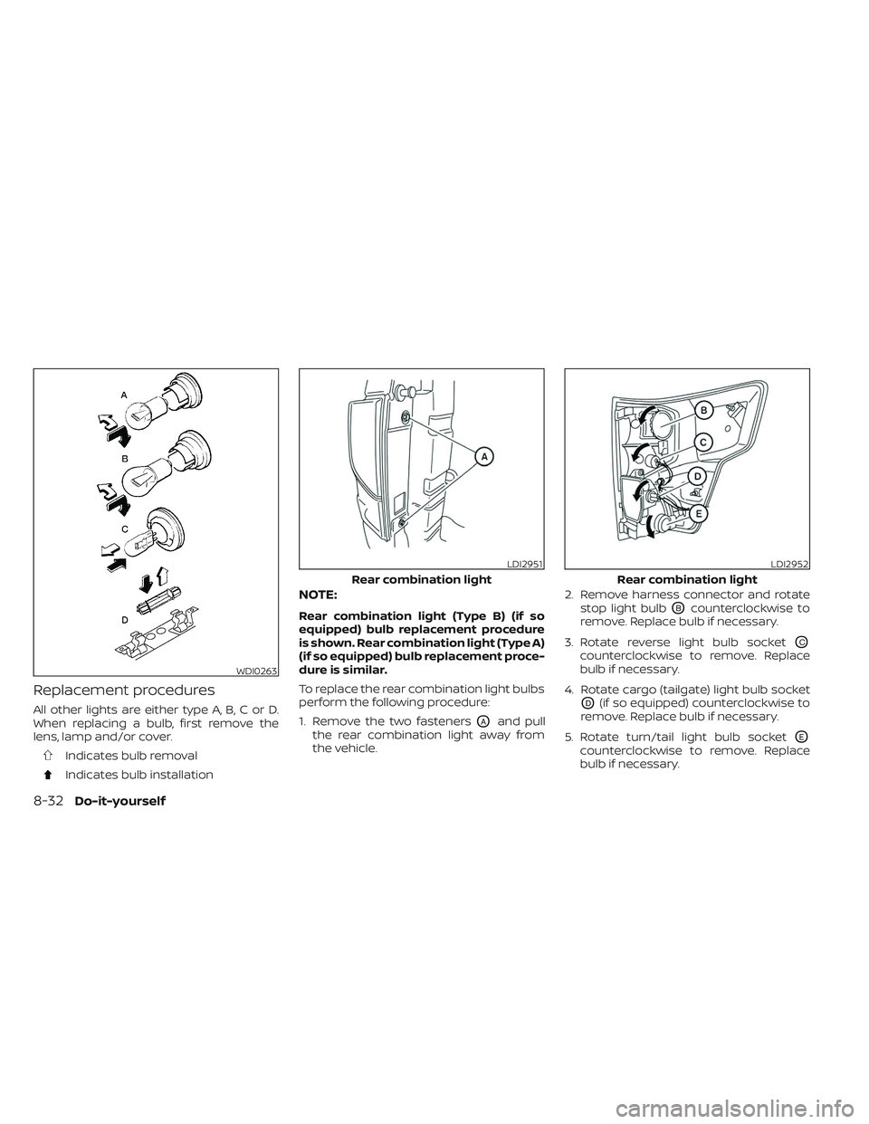
All other lights are either type A, B, C or D.
When replacing a bulb, first remove the
lens, lamp and/or cover.
Indicates bulb removal
Indicates bulb installation
NOTE:
Rear combination light (Type B) (if so
equipped) bulb replacement procedure
is shown. Rear combination light (Type A)
(if so equipped) bulb replacement proce-
dure is similar.
To replace the rear combination light bulbs
perform the following procedure:
1. Remove the two fasteners
OAand pull
the rear combination light away from
the vehicle. 2. Remove harness connector and rotate
stop light bulb
OBcounterclockwise to
remove. Replace bulb if necessary.
3. Rotate reverse light bulb socket
OC
counterclockwise to remove. Replace
bulb if necessary.
4. Rotate cargo (tailgate) light bulb socket
OD(if so equipped) counterclockwise to
remove. Replace bulb if necessary.
5. Rotate turn/tail light bulb socket
OE
counterclockwise to remove. Replace
bulb if necessary.
WDI0263
LDI2951
Rear combination light
LDI2952
Rear combination light
8-32Do-it-yourself