2022 NISSAN TITAN display
[x] Cancel search: displayPage 465 of 635
4. Lower the vehicle slowly until the tiretouches the ground. Then, with the
wheel nut wrench, tighten the wheel
nuts securely in the sequence illustrated
(
O1,O2,O3,O4,O5,O6). Lower the vehicle
completely.
WARNING
• Incorrect wheel nuts or improperly
tightened wheel nuts can cause the
wheel to become loose or come off.
This could cause an accident.
• Do not use oil or grease on the wheel
studs or nuts. This could cause the
nuts to become loose.
• Retighten the wheel nuts when the
vehicle has been driven for 600 miles
(1,000 km) (also in cases of a flat tire,
etc.).
As soon as possible, tighten the wheel
nuts to the specified torque with a
torque wrench.
Wheel nut tightening torque:
Non-XD models: 98 f t-lb (133 N·m)
XD models: 131 f t-lb (177 N·m) The wheel nuts must be kept tightened
to specification at all times. It is recom-
mended that wheel nuts be tightened to
specifications at each lubrication
interval.
Adjust tire pressure to the COLD
pressure.
COLD pressure: Af ter vehicle has been
parked for 3 hours or more or driven less
than 1 mi. (1.6 km).
COLD tire pressures are shown on the
Tire and Loading Information label af-
fixed to the driver side center pillar.
Af ter adjusting tire pressure to the COLD
tire pressure, the display (if so equipped)
of the tire pressure information may
show higher pressure than the COLD tire
pressure af ter the vehicle has been
driven more than 1 mi. (1.6 km). This is
because the tire pressure increases as
the tire temperature rises. This does not
indicate a system malfunction.
5. Securely store the tools and jacking
equipment in the vehicle. For additional
information, see the “Getting the spare
tire and tools (Crew and King Cab® mod-
els)” (P. 6-4).
WARNING
• Always make sure that the spare tire
and jacking equipment are properly
secured af ter use. Such items can be-
come dangerous projectiles in an ac-
cident or sudden stop.
• The spare tire is designed for emer-
gency use. For additional informa-
tion, see “Wheels and tires” (P. 8-33).
In case of emergency6-9
Page 492 of 635
WARNING
• Prolonged and repeated contact
with used engine oil may cause skin
cancer.
• Try to avoid direct skin contact with
used oil. If skin contact is made, wash
thoroughly with soap or hand
cleaner as soon as possible.
• Keep used engine oil out of reach of
children.
4. Loosen the oil filter with an oil filter wrench by turning it counterclockwise.
Remove the oil filter by turning it by
hand.
5. Wipe the engine oil filter mounting sur- face with a clean rag.
CAUTION
Be sure to remove any old gasket ma-
terial remaining on the sealing surface
of the engine. Failure to do so could
lead to an oil leak and engine damage.
• The dipstick must be inserted in
place to prevent oil spillage from the
dipstick hole when filling the engine
with oil. 6. Coat the gasket on the new filter with
clean engine oil.
7. Screw in the oil filter clockwise until a slight resistance is felt, then tighten addi-
tionally more than 2/3 turn.
Oil filter tightening torque: 11 to 15 f t-lb (15.0 to 21.0 N·m)
8. Clean and re-install the drain plug with a new washer. Securely tighten the drain
plug with a wrench. Do not use exces-
sive force.
Drain plug tightening torque: 22 to 29 f t-lb (29.4 to 39.2 N·m)
9. Refill the engine with the recommended oil through the oil filler opening, and in-
stall the oil filler cap securely.
For additional information about drain and
refill capacity, see “Recommended fluids/
lubricants and capacities” (P. 10-2). The
drain and refill capacity depends on the oil
temperature and drain time. Use these
specifications for reference only. Always
use the dipstick to determine the proper
amount of oil in the engine. 10. Start the engine and check for leakage
around the drain plug and the oil filter.
Correct as required. Turn the engine off
and wait more than 15 minutes. Check
the oil level with the dipstick. Add en-
gine oil if necessary.
Af ter the operation
1. Reinstall plate in reverse order ofremoval.
2. Lower the vehicle carefully to the ground.
3. Reset oil and oil filter maintenance re- minder. For additional information, see
“Vehicle information display” (P. 2-23).
• Dispose of waste oil and filter properly.
• Check your local regulations.
8-12Do-it-yourself
Page 495 of 635
WINDSHIELD-WASHER FLUID
RESERVOIR
Fill the windshield-washer fluid reservoir
periodically. Add windshield-washer fluid
when the “Low Washer Fluid” warning mes-
sage shows on the vehicle information
display.
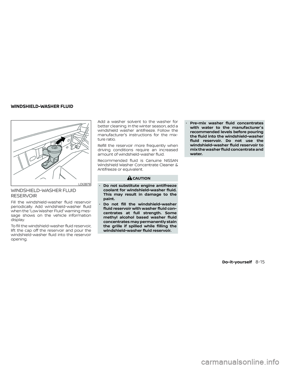
To fill the windshield-washer fluid reservoir,
lif t the cap off the reservoir and pour the
windshield-washer fluid into the reservoir
opening.Add a washer solvent to the washer for
better cleaning. In the winter season, add a
windshield washer antifreeze. Follow the
manufacturer's instructions for the mix-
ture ratio.
Refill the reservoir more frequently when
driving conditions require an increased
amount of windshield-washer fluid.
Recommended fluid is Genuine NISSAN
Windshield Washer Concentrate Cleaner &
Antifreeze or equivalent.
CAUTION
• Do not substitute engine antifreeze
coolant for windshield-washer fluid.
This may result in damage to the
paint.
• Do not fill the windshield-washer
fluid reservoir with washer fluid con-
centrates at full strength. Some
methyl alcohol based washer fluid
concentrates may permanently stain
the grille if spilled while filling the
windshield-washer fluid reservoir. •
Pre-mix washer fluid concentrates
with water to the manufacturer's
recommended levels before pouring
the fluid into the windshield-washer
fluid reservoir. Do not use the
windshield-washer fluid reservoir to
mix the washer fluid concentrate and
water.
LDI2879
WINDSHIELD-WASHER FLUID
Do-it-yourself8-15
Page 513 of 635

Reverse steps to install bulbs and rear
combination light.If you have a flat tire, see “Flat tire”
(P. 6-3).
TIRE PRESSURE
Tire Pressure Monitoring System
(TPMS)
WARNING
Radio waves could adversely af-
fect electric medical equipment.
Those who use a pacemaker
should contact the electric medi-
cal equipment manufacturer for
the possible influences before
use.
This vehicle is equipped with the Tire
Pressure Monitoring System (TPMS).
It monitors tire pressure of all four
tires except the spare. When the low
tire pressure warning light is lit and
the “Tire Pressure Low - Add Air”
warning appears in the vehicle infor-
mation display, one or more of your
tires is significantly under-inflated. If equipped, the system also displays
pressure of all tires (except the spare
tire) on the display screen by send-
ing a signal from a sensor that is
installed in each wheel.
The TPMS will activate only when the
vehicle is driven at speeds above
16 mph (25 km/h). Also, this system
may not detect a sudden drop in tire
pressure (for example a flat tire while
driving).
For additional information, see
“Warning lights, indicator lights and
audible reminders” (P. 2-12), “Tire
Pressure Monitoring System (TPMS)”
(P. 5-5), and “Flat tire” (P. 6-3).
Tire inflation pressure
Check the tire pressures (including
the spare) of ten and always prior to
long distance trips. The recom-
mended tire pressure specifications
are shown on the F.M.V.S.S. certifica-
tion label or the Tire and Loading
WHEELS AND TIRES
Do-it-yourself8-33
Page 610 of 635
Trailer brake controller unit (if so
equipped)
The Trailer Brake Controller Unit (TBCU), lo-
cated on the lower instrument panel, is a
device that assists the vehicle in having
effective and smooth braking while towing
a trailer.
Operating modes:
•Automatic mode: This is the normal op-
eration of the TBCU depending on the
gain and boost settings adjusted by the
customer. This mode will activate when
vehicle brake pedal is pressed.
• Manual mode: This mode is initiated by
adjusting the manual control lever from
resting position. This mode will provide
output power to trailer brakes without
applying the vehicle brake pedal. To determine the output operation of the
system:
•
Gain + and Gain - : Used to increase or
decrease the braking force supplied to
the trailer brakes. To adjust the gain, press
Gain + or Gain - to the desired point (0-10).
For example: gain setting 6.0 is a typical
starting point for heavy loads.
• Boost: Used to adjust the feel of the au-
tomatic brake event that occurs when
the vehicle brake pedal is applied. To set
up boost, press Boost button once to dis-
play for current boost setting (display for
3 seconds). Keep pressing to increase
boost level until the desired level (0-3) is
achieved.
• Manual Control Lever: Provides brake
output power to trailer brakes without
applying the vehicle brake pedal. The
amount of brake output supplied corre-
sponds to the amount of pinch pressure
applied to the manual control lever.
10-48Technical and consumer information
Page 624 of 635
Top tether strap anchor point
locations...................1-32Child safety rear door lock..........3-9Cleaning exterior and interior......7-2,7-4Climate control seat switch.........2-53Cold weather driving............5-129Console light..................2-89Controls
Heater and air conditioner controls. .4-38Heater and air conditioner controls
(manual)...................4-28CoolantCapacities and recommended
fuel/lubricants
...............10-2Changing engine coolant.........8-6Checking engine coolant level......8-6Engine coolant temperature gauge. . .2-8Corrosion protection..............7-7Cruise control................ .5-49Cup holders...................2-77Curtain side-impact and rollover
air bag......................1-79
D
Daytime Running Light System......2-50Digital video disc DVD............4-43Dimensions and weights..........10-11Dimmer switch for instrument panel. . .2-51Display
Information display............2-23Door locks................... .3-4Drive belt....................8-20
Driving
Cold weather driving...........5-129Driving with automatic
transmission................5-19Precautions when starting
and driving...............5-4, 5-11Driving the vehicle...............5-18Dual power moonroof............2-86
E
Eco Drive Report...............5-114Economy - fuel................5-107Electronic locking rear differential
(E-Lock) system................5-113Electronic locking rear differential
(E-Lock) system switch...........2-60Emergency call (SOS) button........2-63Emergency engine shutoff.......5-15,6-2Emission control information label. . . .10-17Emission control system warranty. . . .10-56EngineBefore starting the engine........5-16Capacities and recommended
fuel/lubricants...............10-2Changing engine coolant.........8-6Changing engine oil.............8-7Changing engine oil filter.........8-7Checking engine coolant level......8-6Checking engine oil level..........8-7Engine compartment check
locations.................. .8-3Engine coolant temperature gauge. . .2-8
Engine cooling system...........8-5Engine oil...................8-7Engine oil and oil filter
recommendation.............10-7Engine oil pressure gauge........2-10Engine oil pressure warning light. . . .2-15Engine oil viscosity.............10-7Engine serial number..........10-16Engine specifications...........10-9Starting the engine............5-17Engine coolant temperature gauge. . . .2-8Engine oil pressure gauge..........2-10Event Data recorders............10-59Exhaust gas (Carbon monoxide)......5-4Explanation of maintenance items.....9-2Explanation of scheduled maintenance
items...................... .9-5Extended storage switch..........2-69Eyeglass case.................2-76
F
F.M.V.S.S. certification label.........10-16Flashers (See hazard warning flasher
switch)......................6-2Flat tire......................6-3Floor mat positioning aid...........7-6Fluid
Brake fluid..................8-14Capacities and recommended
fuel/lubricants...............10-2Engine coolant................8-5Engine oil...................8-7
11-2
Page 629 of 635
T
Tachometer...................2-8Tailgate.................... .3-34Temperature gauge
Engine coolant temperature gauge. . .2-8Thef t (NISSAN Vehicle Immobilizer System),
engine start...............2-40, 5-16Three-way catalyst...............5-4Tie down hooks................3-38TireFlat tire................... .6-3Spare tire...............6-4, 8-46Tire and Loading Information label. .10-17Tire chains.................8-42Tire pressure................8-33Tire rotation.................8-43Tires of 4-wheel drive...........8-46Types of tires................8-41Uniform tire quality grading......10-55Wheel/tire size...............10-10Wheels and tires..........8-33, 10-10Tire pressure................. .8-33Low tire pressure warning light.....2-18Tire Pressure Monitoring System
(TPMS)................... .5-5, 6-3Tow mode switch...............2-63Towing
2-wheel drive models...........6-15Flat towing................ .10-54Towing load/specification.......10-36Trailer towing...............10-32Towing a trailer................10-32Towing your vehicle..............6-13
Traffic Sign Recognition (TSR)........5-24Trailer Brake Controller Unit (TBCU). . . .2-63Transceiver
HomeLink® Universal
Transceiver
.......2-90, 2-91, 2-93, 2-94Transfer case shif ting procedures. . . .5-108TransmissionDriving with automatic
transmission
................5-19Travel (See registering a vehicle in
another country)...............10-15Trip odometer..................2-7Truck - camper loading...........10-30Truck box................... .3-34Turn signal switch...............2-51
U
Under seat storage bin.....2-71,2-75,2-76Uniform tire quality grading........10-55USB/iPod® Charging Ports.........2-68Using 4-wheel drive.............5-107
V
Vanity mirror..................3-28Variable voltage control system......8-19Vehicle dimensions and weights.....10-11Vehicle Dynamic Control (VDC) OFF
switch..................... .2-58Vehicle Dynamic Control (VDC)
system.....................5-120Vehicle identification.............10-15
Vehicle identification number (VIN). . . .10-15Vehicle identification number (VIN)
(Chassis number)..............10-15Vehicle identification number (VIN)
plate...................... .10-15Vehicle immobilizer system.....2-40, 5-16Vehicle information display.........2-23Vehicle loading information........10-20Vehicle recovery.............6-15,6-16Vehicle security system...........2-39Vehicle security system (NISSAN
Vehicle Immobilizer System),
engine start
...............2-40, 5-16Vents......................4-28Visors......................3-28Voltmeter....................2-10
W
Warning
Air bag warning light........1-83, 2-16Battery charge warning light......2-15Brake warning light............2-14Engine oil pressure warning light. . . .2-15Hazard warning flasher switch......6-2Loose fuel cap warning..........2-33Low fuel warning
light............2-16,2-21, 2-33, 2-34Low tire pressure warning light.....2-18Low windshield-washer fluid
warning light................2-33Passenger air bag and status light. . .1-63Seat belt warning light..........2-16
11-7