2022 NISSAN TITAN display
[x] Cancel search: displayPage 318 of 635

TROUBLESHOOTING
SymptomRemedy
Monitor does not power on Verif y the vehicle is in the ON or ACC position.
Verif y the battery is installed correctly in the remote control.
Verif y the in-line fuse protection is good. Refer to the RSI system installation instructions for vehicle-specific fuse location.
Monitor front panel controls
flash red For further diagnosis, it is recommended that you visit a NISSAN dealer.
System frozen - will not
respond Sof t reset the system by pressing and holding the power button on the top of the driver side monitor for 5 seconds.
Hard reset the system by turning the ignition off, then back on.
No picture Check that the signal source is connected.
Check the menu source setting. Match your monitor mode with the source correctly.
No sound or distorted sound Make sure that the external media device is connected properly, and all cables are securely inserted into the appropriate jacks.
Verif y that the batteries in the headphones are fresh.
If you are using the wireless headphones, make sure you turn on the power and select the correct monitor (A or B).
Verif y the volume is turned up on headphones and the system.
Verif y nothing is blocking the path between the monitor IR sensor and headphones.
When placing the headphones on your head, make sure to observe the Lef t and Right orientation.
The headphones must be oriented correctly (facing forward) to receive the audio signal.
Monitor feels warm When the monitor is in use for a long period of time, the surface will be warm. This is normal.
A Parental Setting message
is displayed, prohibiting
movie playback Enter the 4-digit Parental Password using the remote and then press
.
For additional information, see “Changing parental lock” (P. 4-75).
Cannot connect mobile
device to the internal RSI
Wi-Fi network Check to make sure Wi-Fi is enabled on the mobile device.
Check to make sure RSI is set to Access Point mode.
Check to make sure the correct password is used. For additional information, see “Using Wi-Fi” (P. 4-68).
Cannot connect RSI system
to an external Wi-Fi network Check to make sure RSI is set to Client Mode. Check to make sure the correct password is used.
For additional information, see “Using Wi-Fi” (P. 4-68).
4-76Monitor, climate, audio, phone and voice recognition systems
Page 320 of 635
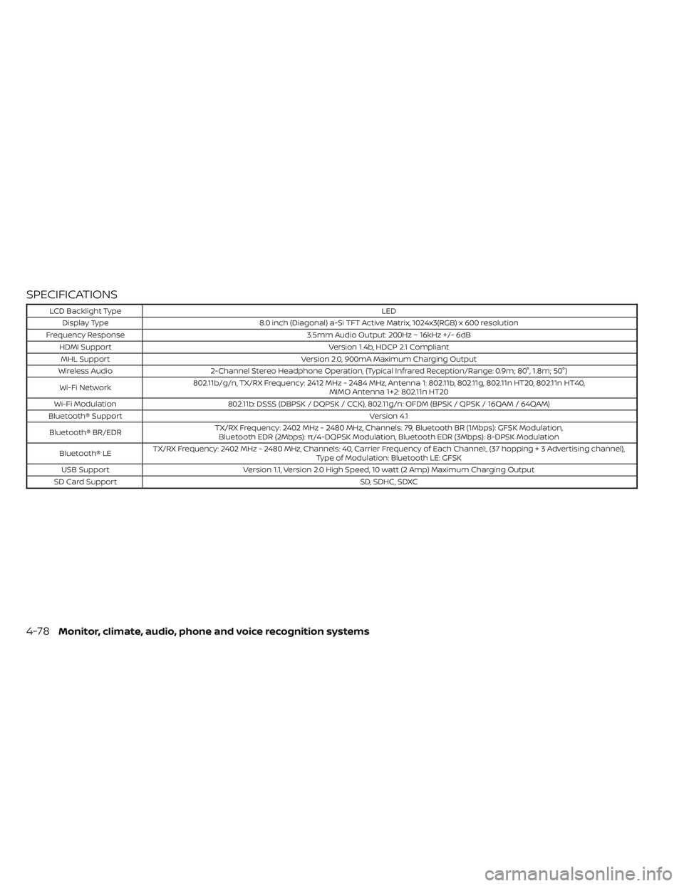
SPECIFICATIONS
LCD Backlight TypeLED
Display Type 8.0 inch (Diagonal) a-Si TFT Active Matrix, 1024x3(RGB) x 600 resolution
Frequency Response 3.5mm Audio Output: 200Hz ~ 16kHz +/- 6dB
HDMI Support Version 1.4b, HDCP 2.1 Compliant
MHL Support Version 2.0, 900mA Maximum Charging Output
Wireless Audio 2-Channel Stereo Headphone Operation, (Typical Infrared Reception/Range: 0.9m; 80°, 1.8m; 50°)
Wi-Fi Network 802.11b/g/n, TX/RX Frequency: 2412 MHz - 2484 MHz, Antenna 1: 802.11b, 802.11g, 802.11n HT20, 802.11n HT40,
MIMO Antenna 1+2: 802.11n HT20
Wi-Fi Modulation 802.11b: DSSS (DBPSK / DQPSK / CCK), 802.11g/n: OFDM (BPSK / QPSK / 16QAM / 64QAM)
Bluetooth® Support Version 4.1
Bluetooth® BR/EDR TX/RX Frequency: 2402 MHz - 2480 MHz, Channels: 79, Bluetooth BR (1Mbps): GFSK Modulation,
Bluetooth EDR (2Mbps): π/4-DQPSK Modulation, Bluetooth EDR (3Mbps): 8-DPSK Modulation
Bluetooth® LE TX/RX Frequency: 2402 MHz - 2480 MHz, Channels: 40, Carrier Frequency of Each Channel:, (37 hoppin
g+3Advertisingchannel),
Type of Modulation: Bluetooth LE: GFSK
USB Support Version 1.1, Version 2.0 High Speed, 10 watt (2 Amp) Maximum Charging Output
SD Card Support SD, SDHC, SDXC
4-78Monitor, climate, audio, phone and voice recognition systems
Page 339 of 635

WARNING
Do not operate the push-button igni-
tion switch while driving the vehicle ex-
cept in an emergency. (The engine will
stop when the ignition switch is pushed
three consecutive times in quick suc-
cession or the ignition switch is pushed
and held for more than 2 seconds.) If
the engine stops while the vehicle is
being driven, this could lead to a crash
and serious injury. When the ignition switch is pushed without
depressing the brake pedal, the ignition
switch position will illuminate as follows:
Push center:
• Once to change to ACC.
• Two times to change to ON.
• Three times to return to OFF.
The ignition switch will automatically re-
turn to the LOCK position when any door is
either opened or closed with the switch in
the OFF position.
The ignition lock is designed so that the
ignition switch position cannot be placed
in the OFF position until the shif t lever is
moved to the P (Park) position.
When the ignition switch cannot be pushed
toward the OFF position, proceed as fol-
lows:
1. Move the shif t lever into the P (Park)
position.
2. Push the ignition switch. The ignition switch position will change to the ON
position.
3. Push the ignition switch again to the OFF position. The shif t lever can be moved from the P
(Park) position if the ignition switch is in
the ON position and the brake pedal is
depressed.
If the battery of the vehicle is discharged,
the push-button ignition switch cannot
be moved from the LOCK position.
Some indicators and warnings for opera-
tion are displayed in the meter. For addi-
tional information, see “Vehicle information
display warnings and indicators” (P. 2-32).
LSD2014
PUSH-BUTTON IGNITION SWITCH
Starting and driving5-13
Page 347 of 635
Apply the parking brake. When parking on a
hill, apply the parking brake first, then move
the shif t lever into the P (Park) position.
R (Reverse)
CAUTION
To prevent transmission damage, use
the R (Reverse) position only when the
vehicle is completely stopped.
Use the R (Reverse) position to back up.
Make sure the vehicle is completely
stopped before selecting the R (Reverse)
position. The brake pedal must be de-
pressed to move the shif t lever from P
(Park), N (Neutral) or any drive position to
R (Reverse).
N (Neutral)
Neither forward nor reverse gear is en-
gaged. The engine can be started in this
position. You may shif t to N (Neutral) and
restart a stalled engine while the vehicle is
moving.
D (Drive)
Use this position for all normal forward
driving.
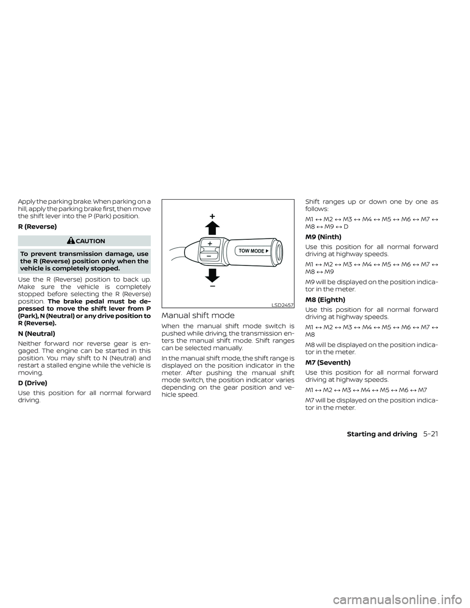
Manual shif t mode
When the manual shif t mode switch is
pushed while driving, the transmission en-
ters the manual shif t mode. Shif t ranges
can be selected manually.
In the manual shif t mode, the shif t range is
displayed on the position indicator in the
meter. Af ter pushing the manual shif t
mode switch, the position indicator varies
depending on the gear position and ve-
hicle speed. Shif t ranges up or down one by one as
follows:
M1
↔M2 ↔M3 ↔M4 ↔M5 ↔M6 ↔M7 ↔
M8 ↔M9 ↔D
M9 (Ninth)
Use this position for all normal forward
driving at highway speeds.
M1 ↔M2 ↔M3 ↔M4 ↔M5 ↔M6 ↔M7 ↔
M8 ↔M9
M9 will be displayed on the position indica-
tor in the meter.
M8 (Eighth)
Use this position for all normal forward
driving at highway speeds.
M1 ↔M2 ↔M3 ↔M4 ↔M5 ↔M6 ↔M7 ↔
M8
M8 will be displayed on the position indica-
tor in the meter.
M7 (Seventh)
Use this position for all normal forward
driving at highway speeds.
M1 ↔M2 ↔M3 ↔M4 ↔M5 ↔M6 ↔M7
M7 will be displayed on the position indica-
tor in the meter.
LSD2457
Starting and driving5-21
Page 348 of 635
M6 (Sixth)
Use this position for all normal forward
driving at highway speeds.
M1↔M2 ↔M3 ↔M4 ↔M5 ↔M6
M6 will be displayed on the position indica-
tor in the meter
M5 (Fif th)
For driving up or down long slopes where
engine braking would be advantageous.
Shif t ranges up or down one by one as
follows:
M1 ↔M2 ↔M3 ↔M4 ↔M5
M5 will be displayed on the position indica-
tor in the meter.
M4 (Fourth)
Use for hill climbing or engine braking on
downhill grades.
Shif t ranges up or down one by one as
follows:
M1 ↔M2 ↔M3 ↔M4
M4 will be displayed on the position indica-
tor in the meter.
M3 (Third)
Use for hill climbing or engine braking on
downhill grades.
Shif t ranges up or down one by one as
follows:
M1 ↔M2 ↔M3
M3 will be displayed on the position indica-
tor in the meter.
M2 (Second)
Use for hill climbing or engine braking on
downhill grades.
Shif t ranges up or down one by one as
follows:
M1 ↔M2
M2 will be displayed on the position indica-
tor in the meter.
M1 (First)
Use this position when climbing steep hills
slowly or driving slowly through deep snow,
sand or mud, or for maximum engine brak-
ing on steep downhill grades.
M1 will be displayed on the position indica-
tor on the meter. • Remember not to drive at high speeds for
extended periods of time in lower than
M4 range. This reduces fuel economy.
When shif ting up
Push the shif t switch to the + (up) side.
(Shif ts to higher range.)
When shif ting down
Push the shif t switch to the − (down) side.
(Shif ts to lower range.)
• The transmission will automatically downshif t the gears. (For example, if you
select the 3rd range, the transmission will
shif t down between the 3rd and 1st
gears.)
• Pushing the shif t switch rapidly will shif t the ranges in succession.
When canceling the manual shif t mode
Press and hold the +(UP) button to return
the transmission to the normal driving
mode.
5-22Starting and driving
Page 350 of 635
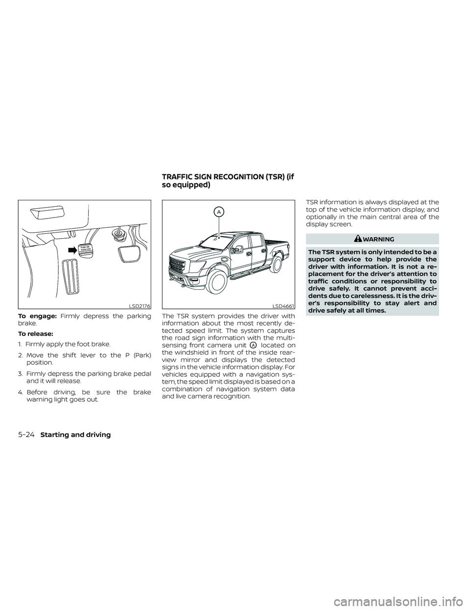
To engage:Firmly depress the parking
brake.
To release:
1. Firmly apply the foot brake.
2. Move the shif t lever to the P (Park) position.
3. Firmly depress the parking brake pedal and it will release.
4. Before driving, be sure the brake warning light goes out. The TSR system provides the driver with
information about the most recently de-
tected speed limit. The system captures
the road sign information with the multi-
sensing front camera unit
OAlocated on
the windshield in front of the inside rear-
view mirror and displays the detected
signs in the vehicle information display. For
vehicles equipped with a navigation sys-
tem, the speed limit displayed is based on a
combination of navigation system data
and live camera recognition. TSR information is always displayed at the
top of the vehicle information display, and
optionally in the main central area of the
display screen.
WARNING
The TSR system is only intended to be a
support device to help provide the
driver with information. It is not a re-
placement for the driver’s attention to
traffic conditions or responsibility to
drive safely. It cannot prevent acci-
dents due to carelessness. It is the driv-
er’s responsibility to stay alert and
drive safely at all times.
LSD2176LSD4661
TRAFFIC SIGN RECOGNITION (TSR) (if
so equipped)
5-24Starting and driving
Page 351 of 635
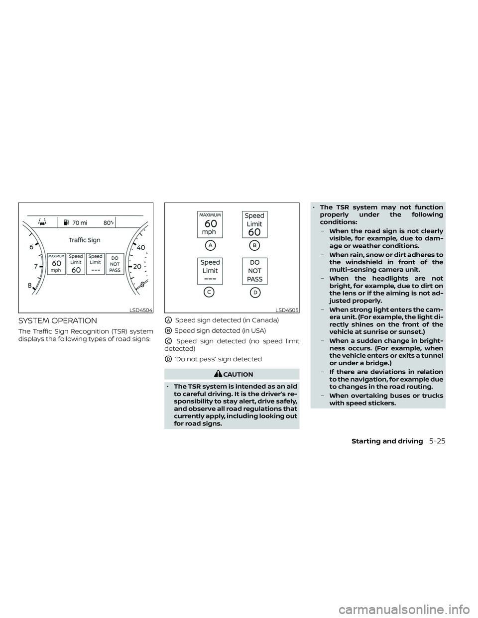
SYSTEM OPERATION
The Traffic Sign Recognition (TSR) system
displays the following types of road signs:
OASpeed sign detected (in Canada)
OBSpeed sign detected (in USA)
OCSpeed sign detected (no speed limit
detected)
OD“Do not pass” sign detected
CAUTION
• The TSR system is intended as an aid
to careful driving. It is the driver’s re-
sponsibility to stay alert, drive safely,
and observe all road regulations that
currently apply, including looking out
for road signs. •
The TSR system may not function
properly under the following
conditions:
– When the road sign is not clearly
visible, for example, due to dam-
age or weather conditions.
– When rain, snow or dirt adheres to
the windshield in front of the
multi-sensing camera unit.
– When the headlights are not
bright, for example, due to dirt on
the lens or if the aiming is not ad-
justed properly.
– When strong light enters the cam-
era unit. (For example, the light di-
rectly shines on the front of the
vehicle at sunrise or sunset.)
– When a sudden change in bright-
ness occurs. (For example, when
the vehicle enters or exits a tunnel
or under a bridge.)
– If there are deviations in relation
to the navigation, for example due
to changes in the road routing.
– When overtaking buses or trucks
with speed stickers.
LSD4504LSD4505
Starting and driving5-25
Page 352 of 635

TURNING THE TRAFFIC SIGN
RECOGNITION (TSR) SYSTEM ON
AND OFF
Perform the following steps to enable or
disable the TSR system.
1. Press the
button until “Settings” dis-
plays in the vehicle information display.
Use the
button to select “Driver As-
sistance.” Then press the ENTER button.
2. Select “Traffic Sign” and press the ENTER button to turn the system on or off.
SYSTEM TEMPORARILY
UNAVAILABLE
If the vehicle is parked in direct sunlight
under high temperature conditions (over
approximately 104°F [40°C]) and then
started, the TSR system may be deacti-
vated automatically. The “Not Available
High Camera Temp” warning message will
appear in the vehicle information display.
Action to take:
When the interior temperature is reduced,
the TSR system will resume operating
automatically.
SYSTEM MALFUNCTION
If the TSR system malfunctions, it will be
turned off automatically and the system
“Malfunction” warning message will appear
in the vehicle information display.
Action to take:
If the TSR “Malfunction” message appears,
pull off the road at a safe location and stop
the vehicle. Turn the engine off and restart
the engine. If the TSR “Malfunction” mes-
sage continues to appear, have the system
checked. It is recommended that you visit a
NISSAN dealer for this service.
SYSTEM MAINTENANCE
The TSR system uses the same multi-
sensing front camera unit that is used by
the Lane Departure Warning (LDW) system,
located in front of the interior rearview mir-
ror. For additional information, see ”System
maintenance” (P. 5-31).
LSD4011
5-26Starting and driving