2022 NISSAN KICKS brake
[x] Cancel search: brakePage 373 of 500
When the VDC system operates, theindicator light in the instrument panel
flashes so note the following:
• The road may be slippery or the systemmay determine some action is required
to help keep the vehicle on the steered
path.
• You may feel a pulsation in the brake pedal and hear a noise or vibration from
under the hood. This is normal and indi-
cates that the VDC system is working
properly.
• Adjust your speed and driving to the road conditions.
For additional information, refer to “Slip in-
dicator light” and ”Vehicle Dynamic Control
(VDC) OFF indicator light” in the ”Instru-
ments and controls” section of this manual.
If a malfunction occurs in the system, the
indicator light comes on in the instru-
ment panel. The VDC system automatically
turns off when these indicator lights are on.
The VDC OFF switch, or the vehicle infor-
mation display, is used to turn off the VDC
system. The
indicator light and the
Automatic Emergency Braking (AEB) sys-
tem warning light illuminate to indicate the
VDC system is off. When the VDC OFF switch, or the vehicle
information display, is used to turn off the
system, the VDC system still operates to
prevent one drive wheel from slipping by
transferring power to a non-slipping drive
wheel. The
indicator light flashes if this
occurs. All other VDC functions are off and
the
indicator light will not flash.
The VDC system is automatically reset to
on when the ignition switch is placed in the
OFF position then back to the ON position.
The computer has a built-in diagnostic fea-
ture that tests the system each time you
start the engine and move the vehicle for-
ward or in reverse at a slow speed. When
the self-test occurs, you may hear a clunk
noise and/or feel a pulsation in the brake
pedal. This is normal and is not an indica-
tion of a malfunction.
indicator light may flash
or illuminate.
• If brake related parts such as brake
pads, rotors and calipers are not
NISSAN recommended or are ex-
tremely deteriorated, the VDC sys-
tem may not operate properly and
the
indicator light may
illuminate.
Starting and driving5-101
Page 374 of 500
•If engine control related parts are not
NISSAN recommended or are ex-
tremely deteriorated, the
indica-
tor light may illuminate.
• When driving on extremely inclined
surfaces such as higher banked cor-
ners, the VDC system may not oper-
ate properly and the
indicator
light may flash or illuminate. Do not
drive on these types of roads.
• When driving on an unstable surface
such as a turntable, ferry, elevator or
ramp, the
indicator light may
flash or illuminate. This is not a mal-
function. Restart the engine af ter
driving onto a stable surface.
• If wheels or tires other than the
NISSAN recommended ones are
used, the VDC system may not oper-
ate properly and the
indicator
light may flash or illuminate.
• The VDC system is not a substitute
for winter tires or tire chains on a
snow covered road.
BRAKE FORCE DISTRIBUTION
During braking while driving through turns,
the system optimizes the distribution of
force to each of the front and rear wheels
depending on the radius of the turn.
indicator light may flash
or illuminate.
• If brake related parts such as brake
pads, rotors and calipers are not
NISSAN recommended or are ex-
tremely deteriorated, the VDC sys-
tem may not operate properly and
the
indicator light may
illuminate. •
If engine control related parts are not
NISSAN recommended or are ex-
tremely deteriorated, the
indica-
tor light may illuminate.
• When driving on extremely inclined
surfaces such as higher banked cor-
ners, the VDC system may not oper-
ate properly and the
indicator
light may flash or illuminate. Do not
drive on these types of roads.
• When driving on an unstable surface
such as a turntable, ferry, elevator or
ramp, the
indicator light may
flash or illuminate. This is not a mal-
function. Restart the engine af ter
driving onto a stable surface.
• If wheels or tires other than the
NISSAN recommended ones are
used, the VDC system may not oper-
ate properly and the
indicator
light may flash or illuminate.
• The VDC system is not a substitute
for winter tires or tire chains on a
snow covered road.
5-102Starting and driving
Page 375 of 500
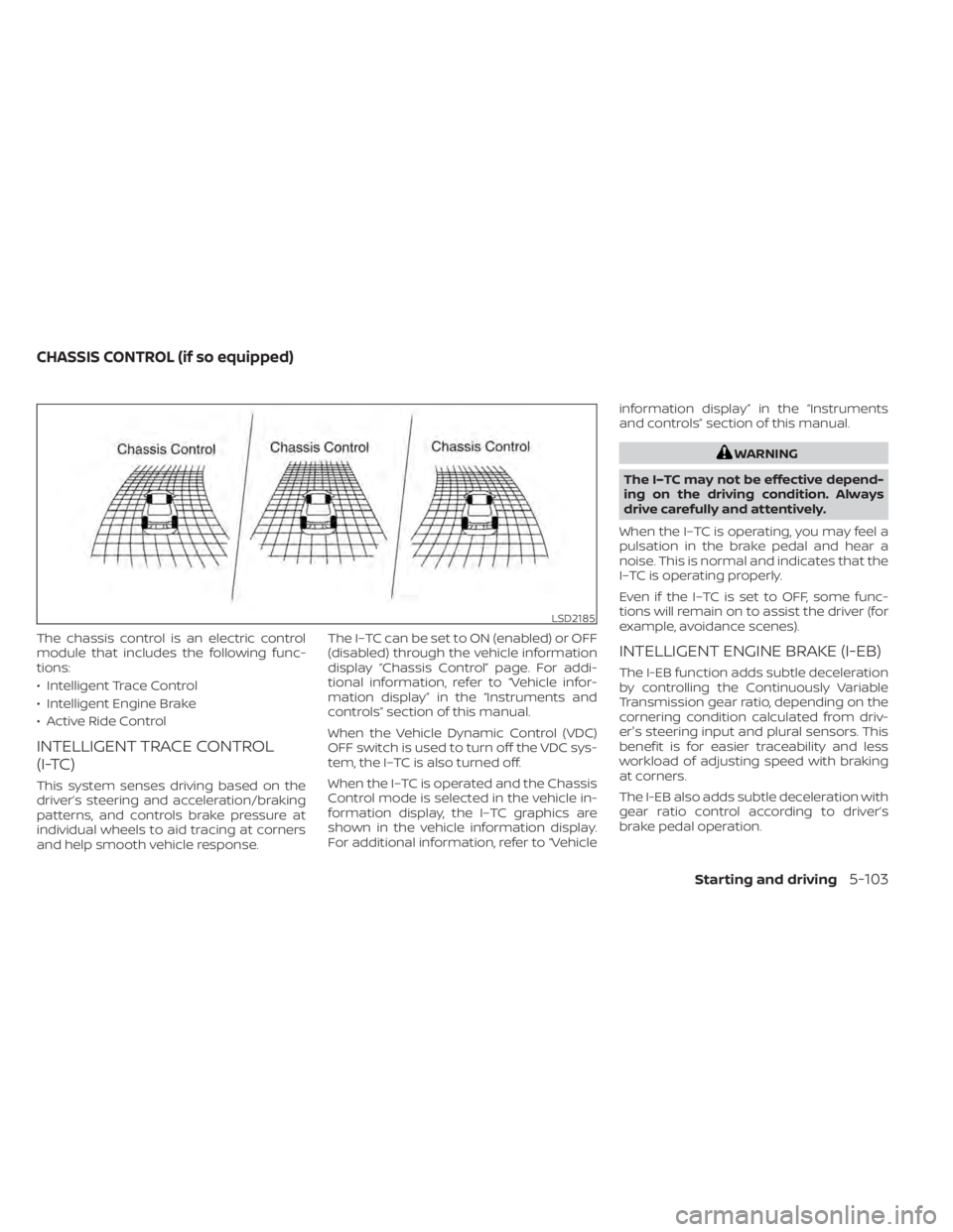
The chassis control is an electric control
module that includes the following func-
tions:
• Intelligent Trace Control
• Intelligent Engine Brake
• Active Ride Control
INTELLIGENT TRACE CONTROL
(I-TC)
This system senses driving based on the
driver’s steering and acceleration/braking
patterns, and controls brake pressure at
individual wheels to aid tracing at corners
and help smooth vehicle response.The I–TC can be set to ON (enabled) or OFF
(disabled) through the vehicle information
display “Chassis Control” page. For addi-
tional information, refer to “Vehicle infor-
mation display” in the “Instruments and
controls” section of this manual.
When the Vehicle Dynamic Control (VDC)
OFF switch is used to turn off the VDC sys-
tem, the I–TC is also turned off.
When the I–TC is operated and the Chassis
Control mode is selected in the vehicle in-
formation display, the I–TC graphics are
shown in the vehicle information display.
For additional information, refer to “Vehicleinformation display” in the “Instruments
and controls” section of this manual.
LSD2185
CHASSIS CONTROL (if so equipped)
Starting and driving5-103
Page 377 of 500
The hill start assist system automatically
keeps the brakes applied to help prevent
the vehicle from rolling backwards in the
time it takes the driver to release the brake
pedal and apply the accelerator when the
vehicle is stopped on a hill.
The hill start assist system will operate au-
tomatically under the following conditions:
• The transmission is shif ted to a forwardor reverse gear.
• The vehicle is stopped completely on a hill by applying the brake.
The maximum holding time is 2 seconds.
Af ter 2 seconds the vehicle will begin to roll
back and the hill start assist system will
stop operating completely.
The hill start assist system will not operate
when the transmission is shif ted to the N
(Neutral) or P (Park) position or on a flat and
level road.
When the Vehicle Dynamic Control (VDC)
indicator light illuminates in the meter, the
hill start assist system will not operate. For
additional information, refer to “Vehicle Dy-
namic Control (VDC) indicator light” in the
“Instruments and controls” section of this
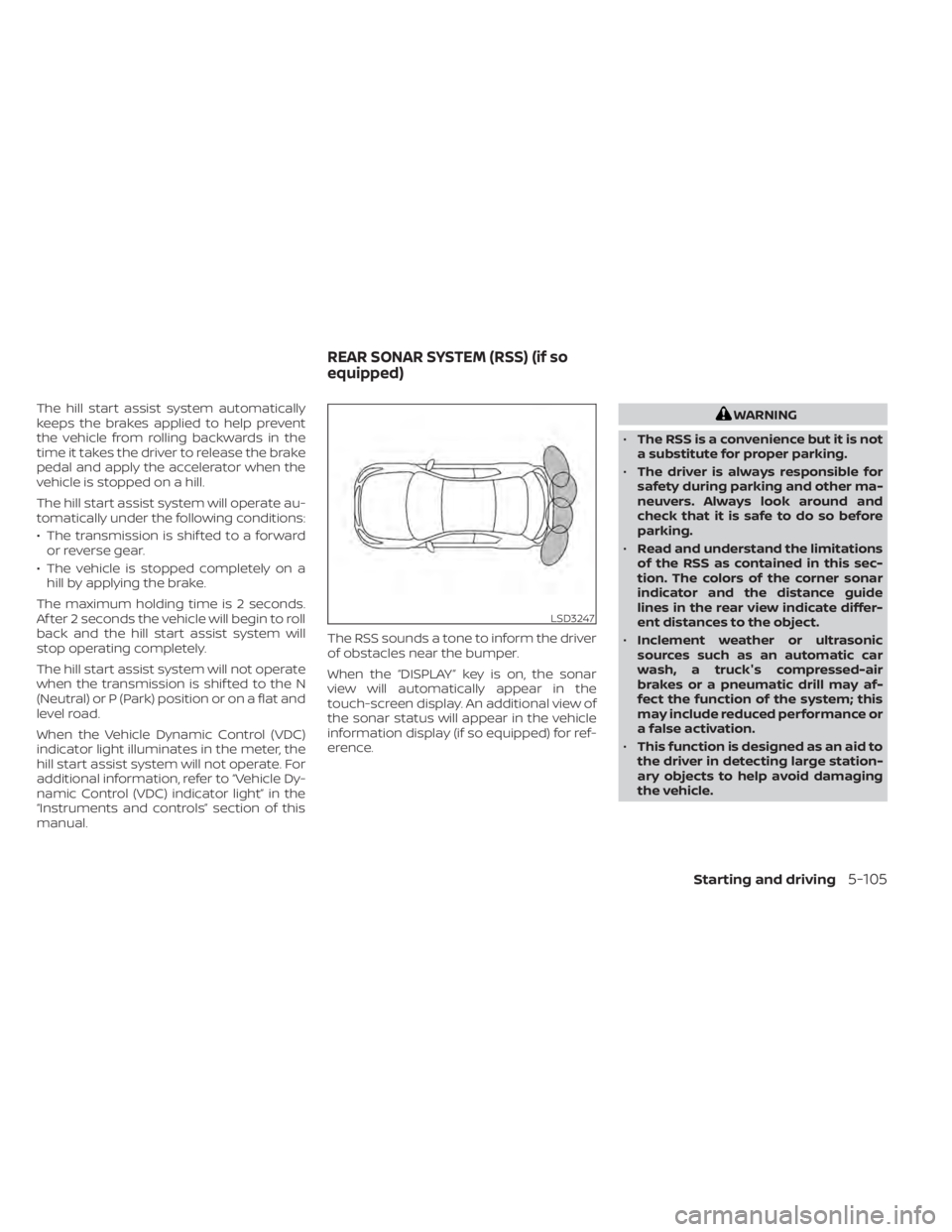
manual. The RSS sounds a tone to inform the driver
of obstacles near the bumper.
When the “DISPLAY” key is on, the sonar
view will automatically appear in the
touch-screen display. An additional view of
the sonar status will appear in the vehicle
information display (if so equipped) for ref-
erence.
Starting and driving5-105
Page 382 of 500
•Inclement weather or ultrasonic
sources such as an automatic car
wash, a truck’s compressed-air
brakes or a pneumatic drill may af-
fect the function of the system; this
may include reduced performance or
a false activation.
• The system is not designed to pre-
vent contact with small or moving
objects. Always move slowly. The
system will not detect small objects
below the bumper or on the ground.
• The system may not detect the fol-
lowing objects: fluff y objects such as
snow, cloth, cotton, glass-wool, etc.;
thin objects such as rope, wire and
chain, etc.; or wedge-shaped objects.
• The system may not detect objects
at speeds above 3 mph (5 km/h) and
may not detect certain angular or
moving objects.
SYSTEM TEMPORARILY
UNAVAILABLE
When sonar blockage is detected, the sys-
tem will be deactivated automatically.
The system is not available until the condi-
tions no longer exist. The sonar sensors may be blocked by tem-
porary ambient conditions such as splash-
ing water, mist or fog. The blocked condi-
tion may also be caused by objects such as
ice, frost or dirt obstructing the sonar sen-
sors.
Action to take:
When the above conditions no longer exist,
the system will resume automatically.
SYSTEM MAINTENANCE
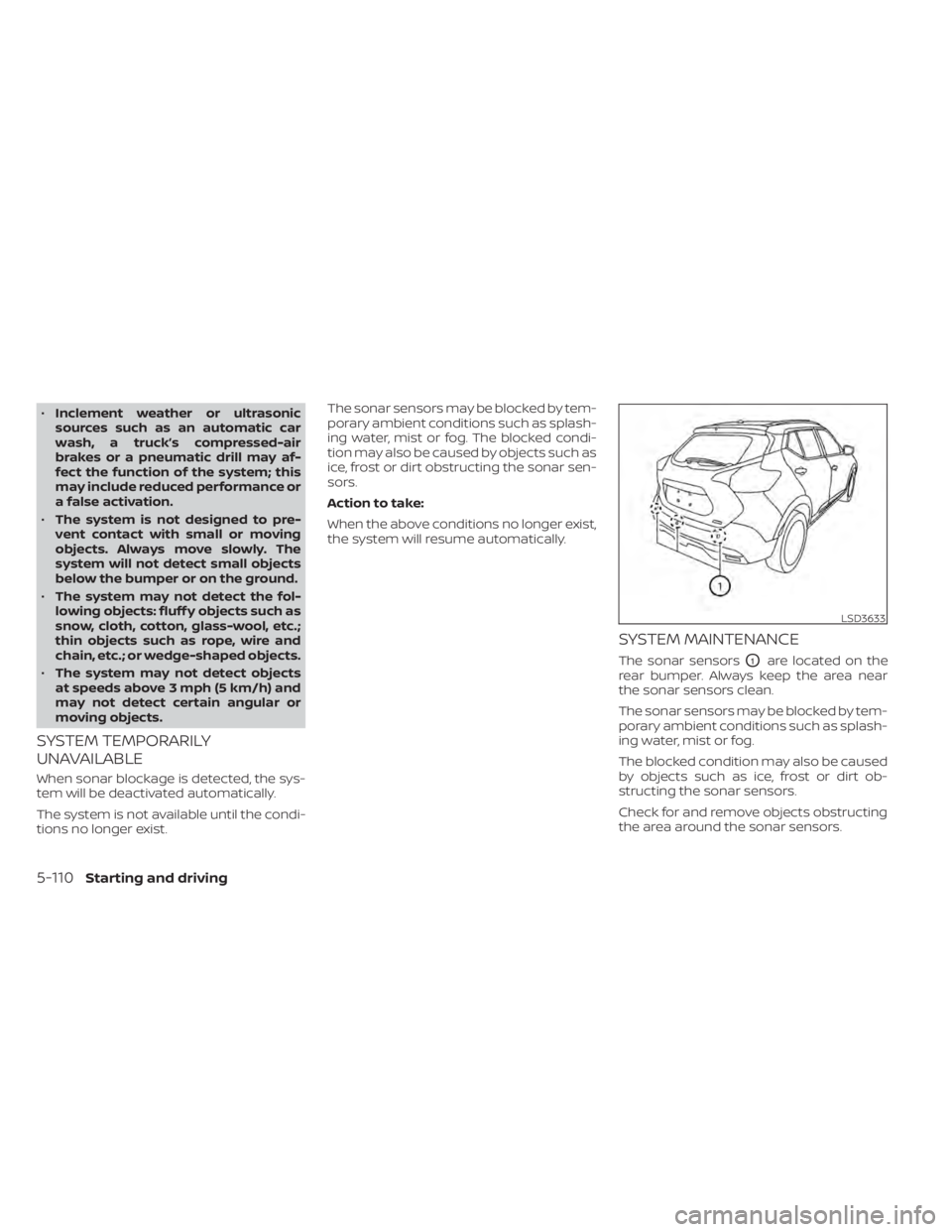
The sonar sensorsO1are located on the
rear bumper. Always keep the area near
the sonar sensors clean.
The sonar sensors may be blocked by tem-
porary ambient conditions such as splash-
ing water, mist or fog.
The blocked condition may also be caused
by objects such as ice, frost or dirt ob-
structing the sonar sensors.
Check for and remove objects obstructing
the area around the sonar sensors.
LSD3633
5-110Starting and driving
Page 390 of 500
CHANGING A FLAT TIRE
If you have a flat tire, follow the instructions
below:
Stopping the vehicle
1. Safely move the vehicle off the road andaway from traffic.
2. Turn on the hazard warning flashers.
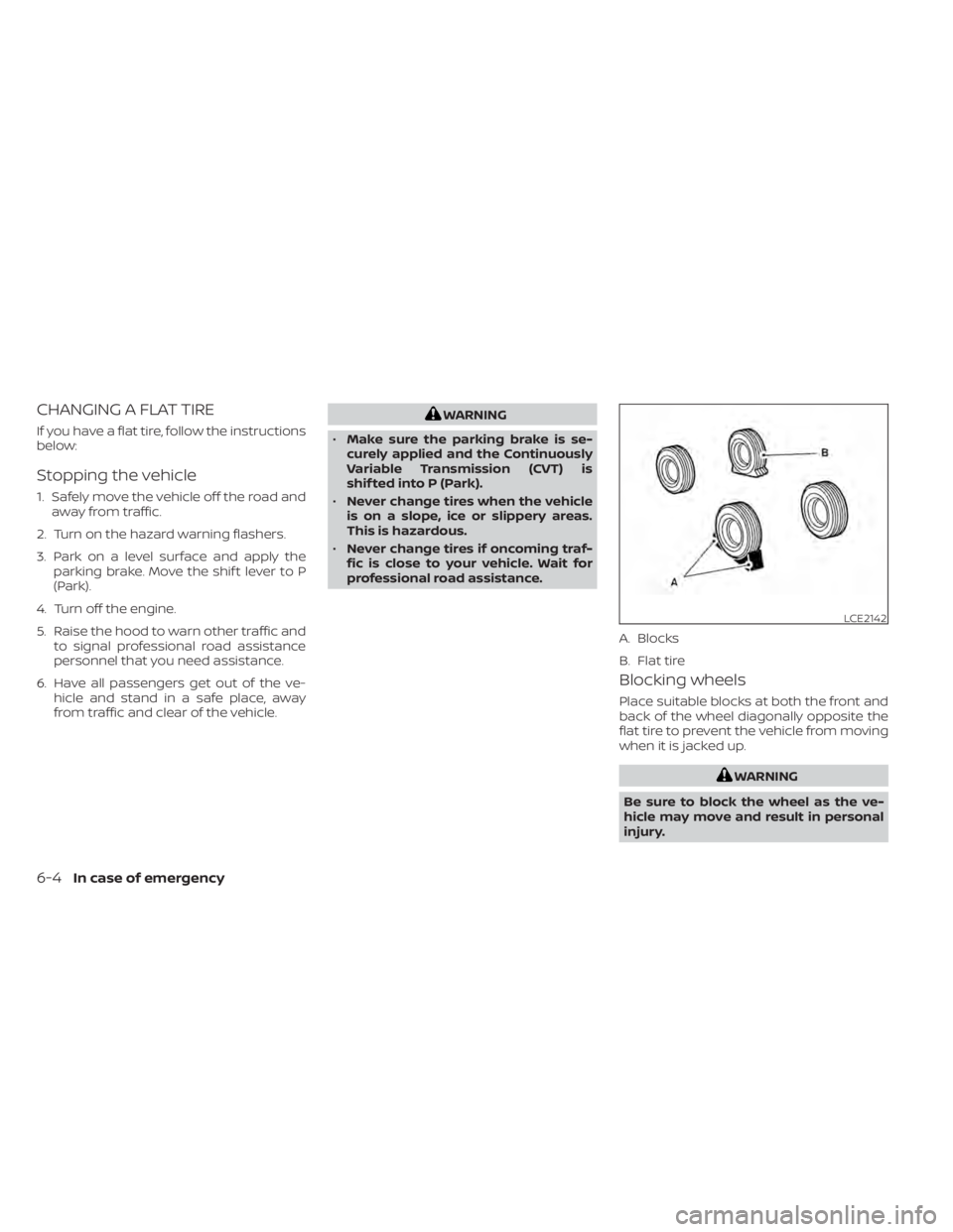
3. Park on a level surface and apply the parking brake. Move the shif t lever to P
(Park).
4. Turn off the engine.
5. Raise the hood to warn other traffic and to signal professional road assistance
personnel that you need assistance.
6. Have all passengers get out of the ve- hicle and stand in a safe place, away
from traffic and clear of the vehicle.
6-4In case of emergency
Page 396 of 500
•Whenever working on or near a bat-
tery, always wear suitable eye pro-
tectors (for example, goggles or in-
dustrial safety spectacles) and
remove rings, metal bands, or any
other jewelry. Do not lean over the
battery when jump starting.
• Do not attempt to jump start a frozen
battery. It could explode and cause
serious injury.
• The automatic engine cooling fan (if
so equipped) may come on at any
time without warning, even if the ig-
nition switch is in the OFF position
and the engine is not running. To
avoid injury, keep hands and other
objects away from it.
WARNING
Always follow the instructions below.
Failure to do so could result in damage
to the charging system and cause per-
sonal injury.
1. If the booster battery is in another ve- hicle, position the 2 vehicles to bring their
batteries near each other.
Do not allow the two vehicles to touch.
2. Apply the parking brake. Move the shif t lever to P (Park). Switch off all unneces-
sary electrical systems (lights, heater, air
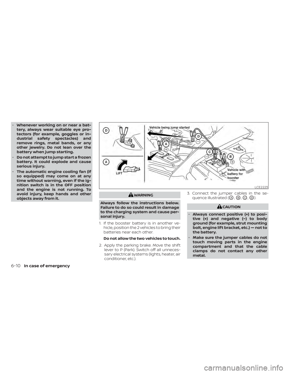
conditioner, etc.). 3. Connect the jumper cables in the se-
quence illustrated (OA,OB,OC,OD).
6-10In case of emergency
Page 406 of 500
When installing Genuine NISSAN floor mats,
follow the installation instructions provided
with the mat and the following:
1. With the ignition in the OFF position, theshif t lever in P (Park) position and with
the parking brake fully applied, position
the floor mat in the floorwell so that the
floor mat grommet holes are aligned
with the hook(s).
2. Secure the grommet holes into the hook(s) and ensure that the floor mat is
properly positioned.
3. Make sure the floor mat does not inter- fere with pedal operation. With the igni-
tion still in the OFF position, the shif t le-
ver in the P (Park) position and with the
parking brake applied, fully apply and re-
lease all pedals. The floor mat must not
interfere with pedal operation or prevent
the pedal from returning to its normal
position.
It is recommended that you visit a NISSAN
dealer for details about installing the floor
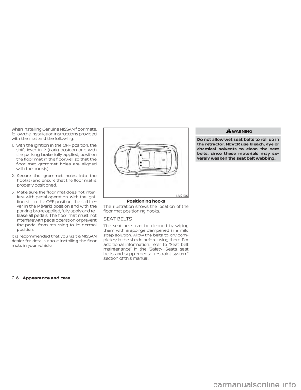
mats in your vehicle. The illustration shows the location of the
floor mat positioning hooks.
SEAT BELTS
The seat belts can be cleaned by wiping
them with a sponge dampened in a mild
soap solution. Allow the belts to dry com-
pletely in the shade before using them. For
additional information, refer to “Seat belt
maintenance” in the “Safety—Seats, seat
belts and supplemental restraint system”
section of this manual.