Page 394 of 559

Le présent appareil est conforme aux
CNR d’Industrie Canada applicables aux
appareils radio exempts de licence.
L’exploitation est autorisée aux deux
conditions suivantes:1. L’appareil ne doit pas produire de
brouillage, et
2. L’utilisateur de l’appareil doit ac-
cepter tout brouillage radioélec-
trique subi, même si le brouillage est
susceptible d’en compromettre le
fonctionnement.
Radio frequency radiation exposure in-
formation:
This equipment complies with FCC and IC
radiation exposure limits set forth for an
uncontrolled environment.
This equipment should be installed and
operated with minimum distance of
30 cm between the radiator and your
body.
This transmitter must not be co-located
or operating in conjunction with any
other antenna or transmitter. Cet équipement est conforme aux lim-
ites d’exposition aux rayonnements IC
établies pour un environnement non
contrôlé.
Cet équipement doit être installé et
utilisé avec un minimum de 30 cm de
distance entre la source de rayonnement
et votre corps.
FCC Notice
Changes or modifications not expressly
approved by the party responsible for
compliance could void the user’s author-
ity to operate the equipment.
Page 421 of 559
The chassis control is an electric control
module that includes the following func-
tions:∙ Intelligent Trace Control
∙ Active Ride Control
INTELLIGENT TRACE CONTROL
(I-TC)
This system senses driving based on the
driver’s steering and acceleration/braking
patterns, and controls brake pressure at
individual wheels to aid tracing at corners
and help smooth vehicle response.
The I-TC can be set to on (enabled) or off
(disabled) through the vehicle information
display “Settings” page. For additional infor-
mation, refer to “Vehicle information dis-
play” in the “Instruments and controls” sec-
tion of this manual.
When the VDC system is turned off, the I-TC
is also turned off.
Page 441 of 559
WARNING
Always follow the instructions below.
Failure to do so could result in damage
to the charging system and cause per-
sonal injury.1. If the booster battery is in another ve- hicle, position the two vehicles to bring
their batteries near each other.
Do not allow the two vehicles to
touch. 2. Apply the parking brake. Move the shif t
lever to P (Park). Switch off all unneces-
sary electrical systems (lights, heater,
air conditioner, etc.).
3. Place the ignition switch in the LOCK position.
4. Connect the jumper cables in the se- quence illustrated (
�A,�B,�C,�D).
Page 470 of 559

∙ If the battery is labeled “do not open” it ismaintenance free and battery fluid
should not be checked. It is recom-
mended that you visit a NISSAN dealer
or a qualified specialist workshop to
confirm the battery’s performance.
∙ Keep the battery surface clean and dry. Clean the battery with a solution of bak-
ing soda and water.
∙ Make certain the terminal connections are clean and securely tightened.
∙ If the vehicle is not to be used for 30 days or longer, disconnect the nega-
tive (-) battery terminal cable to prevent
discharge.
NOTE:
Care should be taken to avoid situations
that can lead to potential battery dis-
charge and potential no-start conditions
such as: 1. Installation or extended use of elec-
tronic accessories that consume bat-
tery power when the engine is not
running (Phone chargers, GPS, DVD
players, etc.)
2. Vehicle is not driven regularly and/or
only driven short distances. In these cases, the battery may need to
be charged to maintain battery health.
Page 471 of 559
CAUTION
∙ Do not ground accessories directly tothe battery terminal. Doing so will by-
pass the variable voltage control sys-
tem and the vehicle battery may not
charge completely.
∙ Use electrical accessories with the en- gine running to avoid discharging the
vehicle battery.
Your vehicle is equipped with a variable
voltage control system. This system mea-
sures the amount of electrical discharge
from the battery and controls voltage gen-
erated by the generator. The current sensor is located near the bat-
tery along the negative battery cable. If you
add electrical accessories to your vehicle,
be sure to ground them to a suitable body
ground such as the frame or engine block
area.
1. Automatic tensioner pulley
2. Generator pulley
3. Water pump pulley
4. Air conditioner compressor pulley
5. Crankshaf t pulley
Page 476 of 559
If any electrical equipment does not oper-
ate, check for an open fuse.
Fuses are used in the passenger and en-
gine compartment. Spare fuses are pro-
vided and can be found in the passenger
compartment fuse box.
When installing a fuse make sure the fuse is
installed in the fuse box securely.ENGINE COMPARTMENT
Page 477 of 559
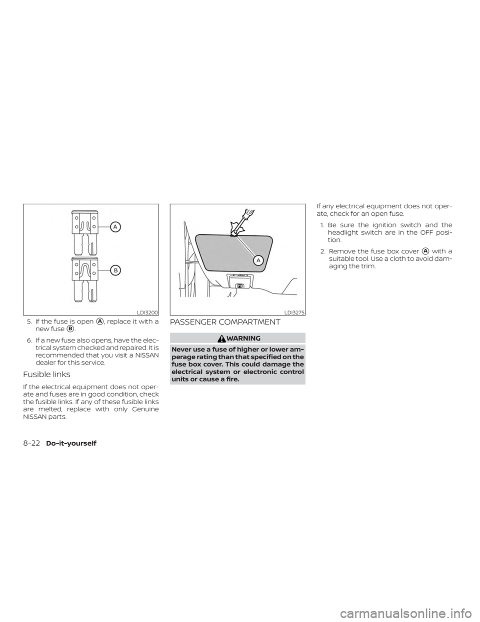
5. If the fuse is open�A, replace it with a
new fuse
�B.
6. If a new fuse also opens, have the elec- trical system checked and repaired. It is
recommended that you visit a NISSAN
dealer for this service.
Fusible links
If the electrical equipment does not oper-
ate and fuses are in good condition, check
the fusible links. If any of these fusible links
are melted, replace with only Genuine
NISSAN parts.
PASSENGER COMPARTMENT
Page 478 of 559
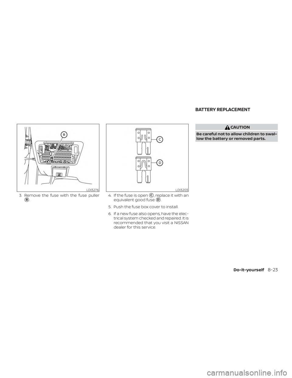
3. Remove the fuse with the fuse puller
�B.4. If the fuse is open�C, replace it with an
equivalent good fuse
�D.
5. Push the fuse box cover to install.
6. If a new fuse also opens, have the elec- trical system checked and repaired. It is
recommended that you visit a NISSAN
dealer for this service.

This system senses driv")