2022 LEXUS RX350 tire pressure reset
[x] Cancel search: tire pressure resetPage 84 of 508

822-1. Instrument cluster
The greater the number of segments
displayed, the greater the driving force
applied.
■G-force (if equipped)
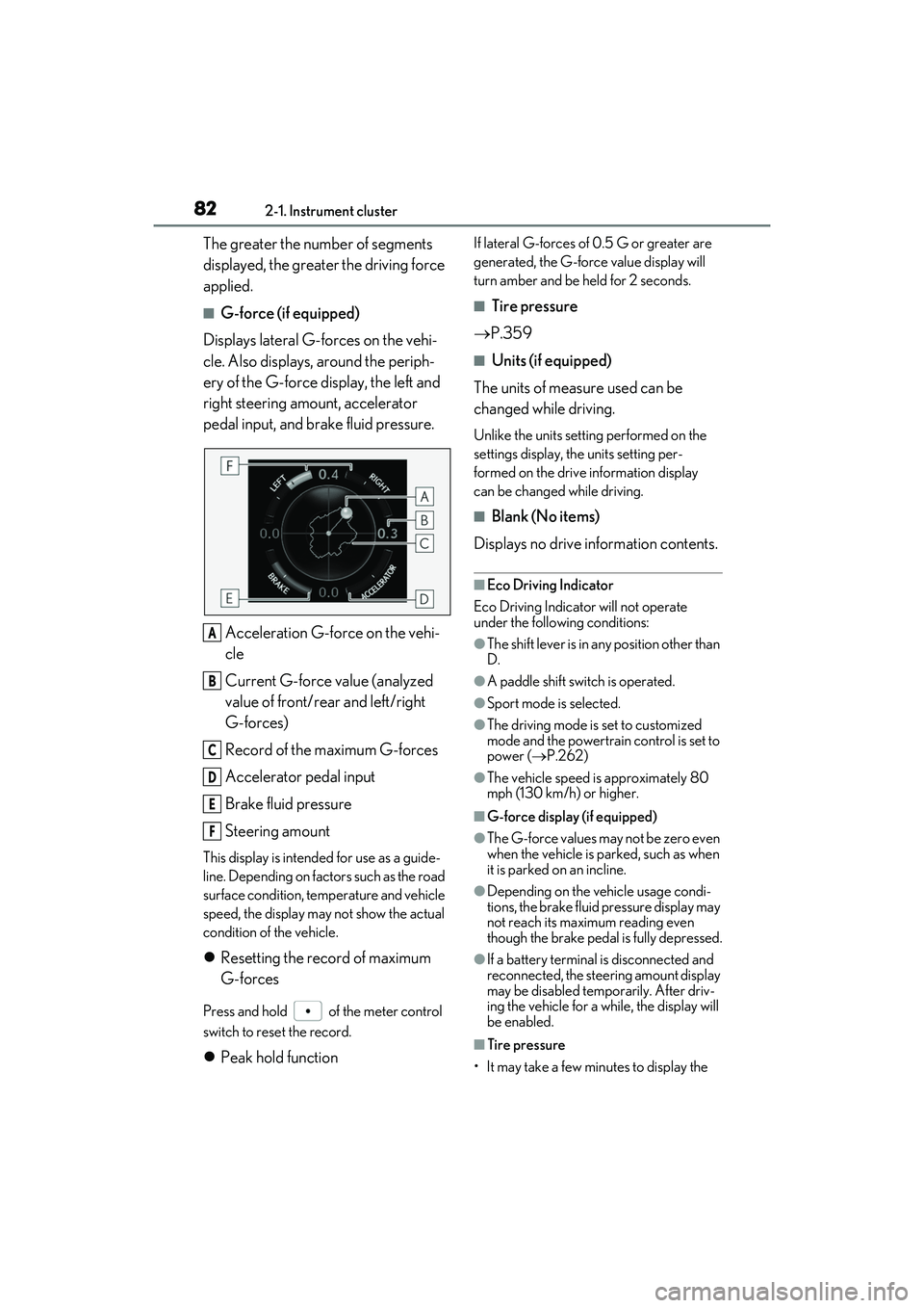
Displays lateral G-forces on the vehi-
cle. Also displays, around the periph-
ery of the G-force display, the left and
right steering amount, accelerator
pedal input, and brake fluid pressure.
Acceleration G-force on the vehi-
cle
Current G-force value (analyzed
value of front/rear and left/right
G-forces)
Record of the maximum G-forces
Accelerator pedal input
Brake fluid pressure
Steering amount
This display is intended for use as a guide-
line. Depending on factors such as the road
surface condition, temperature and vehicle
speed, the display may not show the actual
condition of the vehicle.
Resetting the record of maximum
G-forces
Press and hold of the meter control
switch to reset the record.
Peak hold function
If lateral G-forces of 0.5 G or greater are
generated, the G-forc e value display will
turn amber and be held for 2 seconds.
■Tire pressure
P.359
■Units (if equipped)
The units of measure used can be
changed while driving.
Unlike the units setting performed on the
settings display, th e units setting per-
formed on the drive information display
can be changed while driving.
■Blank (No items)
Displays no drive information contents.
■Eco Driving Indicator
Eco Driving Indicator will not operate
under the following conditions:
●The shift lever is in any position other than
D.
●A paddle shift swit ch is operated.
●Sport mode is selected.
●The driving mode is set to customized
mode and the powertrain control is set to
power (P.262)
●The vehicle speed is approximately 80
mph (130 km/h) or higher.
■G-force display (if equipped)
●The G-force values may not be zero even
when the vehicle is parked, such as when
it is parked on an incline.
●Depending on the vehicle usage condi-
tions, the brake fluid pressure display may
not reach its maximum reading even
though the brake pedal is fully depressed.
●If a battery terminal is disconnected and
reconnected, the steeri ng amount display
may be disabled temp orarily. After driv-
ing the vehicle for a while, the display will
be enabled.
■Tire pressure
• It may take a few minutes to display the
A
B
C
D
E
F
Page 364 of 508

3626-3. Do-it-yourself maintenance
Make sure to adjust the tire pressure to the
specified cold tire infl ation pressure level.
The tire pressure warning system will oper-
ate based on this pressure level.
3 Turn the engine switch to IGNI-
TION ON mode.
4 Select on the multi-information
display.
5 Press or of the meter con-
trol switch, select the “Vehicle Set-
tings” screen and then press the
.
6 Press or of the meter con-
trol switch, select the “TPMS”
screen and then press and hold the
until the tire pressure warn-
ing light blinks slowly 3 times.
“- -” will be displayed for inflation pressure
of each tire on the multi-information dis-
play while the tire pressure warning system
determines the position of each tire.
7 Drive the vehicle at approximately
25 mph (40 km/h) or more for
approximately 10 to 30 minutes
until the inflation pressure of each
tire is displayed on the multi-infor-
mation display.
When position of each tire is determined,
the inflation pressure of each tire will be
displayed on the multi-information display.
If tire inflation pr essure becomes low before the inflation pressure is displayed,
the tire pressure warning light will come
on.
Depending on the vehicle and driving con-
ditions, initialization may take up to
approximately 1 hour to complete.
■Initializing the tire pressure warning sys-
tem
Initialize the system with the tire inflation
pressure adjusted to the specified level.
■If you press the tire pressure warning
reset switch accidentally
If initialization is perf ormed, adjust the tire
inflation pressure to the specified level and
initialize the tire pres sure warning system
again.
■Initialization procedure
●Make sure to carry out initialization after
adjusting the tire inflation pressure.
Also, make sure the tires are cold before
carrying out initialization or tire inflation
pressure adjustment.
●If you have accidentally turned the engine
switch off during initialization, it is not
necessary to press the reset switch again
as initialization will restart automatically
when the engine switch has been turned
to IGNITION ON mode for the next
time.
●If you accidentally press the reset switch
when initialization is not necessary, adjust
the tire inflation pressure to the specified
level when the tires are cold, and conduct
initialization again.
●While the position of each tire is being
determined and the inflation pressures
are not being displayed on the
multi-information display, if the inflation
pressure of a tire drops, the tire pressure
warning light will come on.
■When initialization of the tire pressure
warning system has failed
Initialization may take longer to complete if
the vehicle is driven on an unpaved road.
When performing initialization, drive on a
paved road if possible. Depending on the
driving environment and condition of the
tires, initialization will be completed in
Page 365 of 508

3636-3. Do-it-yourself maintenance
6
Maintenance and care
approximately 10 to 30 minutes. If initializa-
tion is not complete after driving approxi-
mately 10 to 30 minu tes, continue driving
for a while.
If the inflation pressure of each tire is not
displayed after driving for approximately 1
hour, perform the following procedure.
●Park the vehicle in a safe place for
approximately 20 minutes. Then drive
straight (with occasi onal left and right
turns) at approximately 25 mph (40
km/h) or more for approximately 10 to
30 minutes.
However, in the following situations, the tire
inflation pressure will not be recorded and
the system will not operate properly. Per-
form initialization again.
●When operating the tire pressure warn-
ing reset switch, the ti re pressure warning
light does not blink 3 times.
●After performing initialization, the tire
pressure warning light blinks for 1 minute
then stays on while driving.
If the inflation pressure of each tire is still not
displayed, have the vehicle inspected by
your Lexus dealer.
The tire pressure warning valve and
transmitter is equipped with a unique
ID code. When replacing a tire pres-
sure warning valve and transmitter, it is
necessary to register the ID code.
Have the ID code registered by your
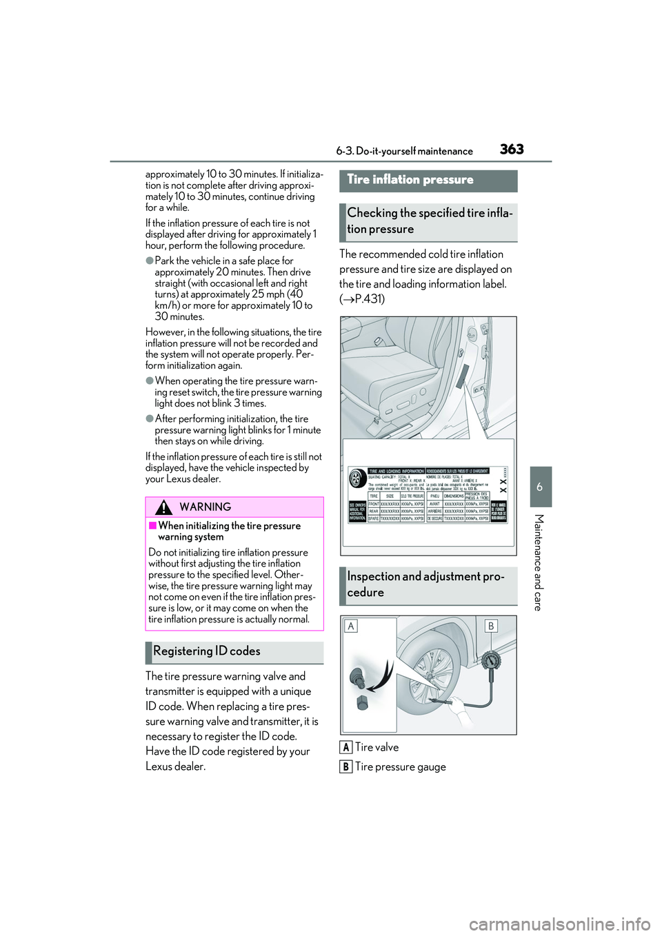
Lexus dealer. The recommended cold tire inflation
pressure and tire size are displayed on
the tire and loading information label.
(
P.431)
Tire valve
Tire pressure gauge
WARNING
■When initializing the tire pressure
warning system
Do not initializing tire inflation pressure
without first adjusting the tire inflation
pressure to the spec ified level. Other-
wise, the tire pressure warning light may
not come on even if the tire inflation pres-
sure is low, or it may come on when the
tire inflation pressure is actually normal.
Registering ID codes
Tire inflation pressure
Checking the specified tire infla-
tion pressure
Inspection and adjustment pro-
cedure
A
B
Page 493 of 508

491Alphabetical Index
Rear window and outside rear view mir-ror defoggers switch ............................ 284
Seat heater switches ................................ 297
Seat ventilator switches .......................... 297
“SOS” button .................................................. 60
Tilt and telescopic steering control switch ...........................................................................135
Tire pressure warning reset switch ....361
Vehicle-to-vehicle distance switch ...222
VSC OFF switch ....................................... 267
Window lock switch .................................. 142
Windshield wiper and washer switch190
Windshield wiper de-icer switch ......289
T
Tachometer........................................................75 Rev indicator ................................................... 76
Rev peak ............................................................ 77
Tail lights Light switch .................................................... 184
Replacing light bulbs................................ 375
The Secondary Collision Brake ............ 266
Theft deterrent system Alarm .................................................................. 67
Engine immobilizer system ..................... 66
Tire inflation pressure Maintenance data...................................... 436
Tire inflation pressure display function.........................................................................359
Warning light ............................................... 397
Tire information ............................................ 440 Glossary......................................................... 444
Size.................................................................... 442
Tire identification number ....................... 441
Uniform Tire Quality Grading............ 442
Tire pressure display .................................. 359
Tire pressure warning system Function ..........................................................359
Initializing .........................................................361
Installing tire pressure warning valves and transmitters ........................................361
Registering ID codes ............................... 363 Warning light ............................................... 397
Tires Chains ............................................................. 272
Checking ....................................................... 357
If you have a flat tire ................................. 406
Inflation pressure ........................................363
Information ................................................... 440
Replacing ...................................................... 406
Rotating tires ............................................... 359
Size ....................................................................436
Snow tires ........................................................ 271
Spare tire ....................................................... 406
Tire inflation pressure display function......................................................................... 359
Tire pressure warning system ............ 359
Warning light ............................................... 397
Tools.................................................................. 407
Top tether strap............................................... 57
Total load capacity ...................................... 430
Towing Dinghy towing .............................................. 169
Emergency towing....................................387
Towing eyelet.............................................. 389
Trailer towing ................................................ 159
TRAC (Traction Control) ........................ 266
Traction Control (TRAC) ........................ 266
Trailer Sway Control.................................. 266
Trailer towing ..................................................159
Transmission Automatic transmission ............................174
Driving mode select switch .................. 262
M mode ............................................................ 177
Paddle shift switches ........................176, 177
Trip meters ........................................................ 78
Turn signal lights Replacing light bulbs................................375
Turn signal lever .......................................... 178
Wattage .......................................................... 437
U
USB charging ports......................................314