2022 KIA NIRO HYBRID EV instrument panel
[x] Cancel search: instrument panelPage 604 of 684

Maintenance
62 7
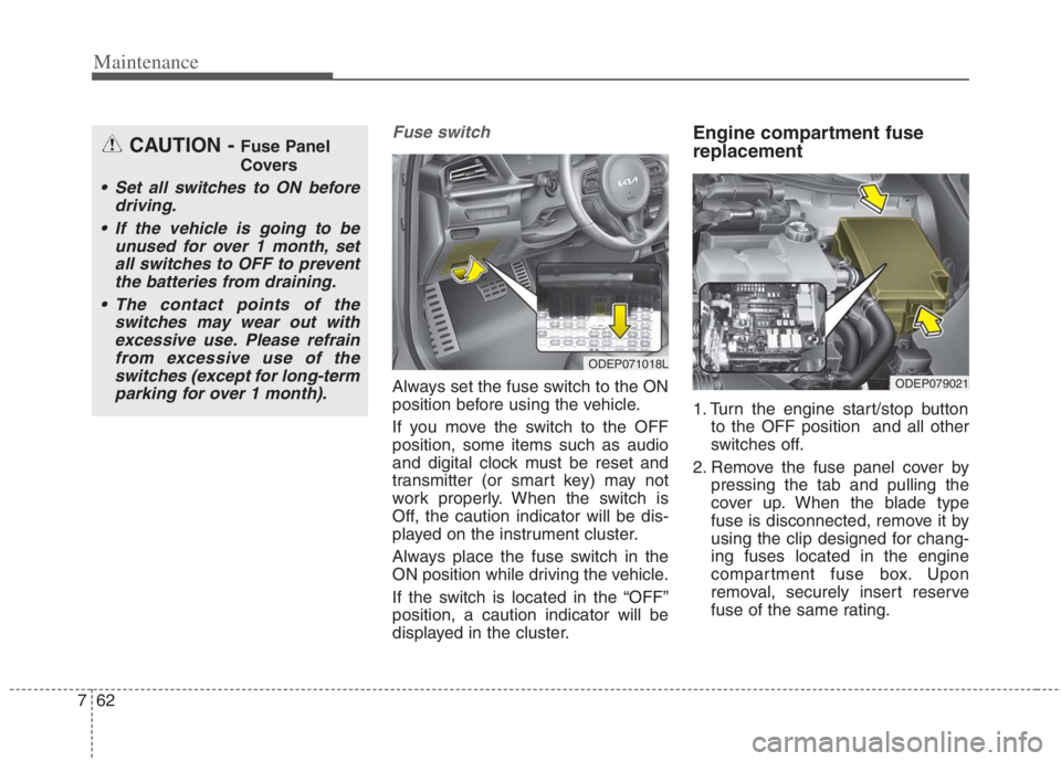
Fuse switch
Always set the fuse switch to the ON
position before using the vehicle.
If you move the switch to the OFF
position, some items such as audio
and digital clock must be reset and
transmitter (or smart key) may not
work properly. When the switch is
Off, the caution indicator will be dis-
played on the instrument cluster.
Always place the fuse switch in the
ON position while driving the vehicle.
If the switch is located in the “OFF”
position, a caution indicator will be
displayed in the cluster.
Engine compartment fuse
replacement
1. Turn the engine start/stop button
to the OFF position and all other
switches off.
2. Remove the fuse panel cover by
pressing the tab and pulling the
cover up. When the blade type
fuse is disconnected, remove it by
using the clip designed for chang-
ing fuses located in the engine
compartment fuse box. Upon
removal, securely insert reserve
fuse of the same rating.
ODEP071018L
ODEP079021
CAUTION - Fuse Panel
Covers
Set all switches to ON before
driving.
If the vehicle is going to be
unused for over 1 month, set
all switches to OFF to prevent
the batteries from draining.
The contact points of the
switches may wear out with
excessive use. Please refrain
from excessive use of the
switches (except for long-term
parking for over 1 month).
Page 609 of 684

767
Maintenance
Instrument panel (Driver’s side fuse panel) (Hybrid)
Fuse NameFuse ratingCircuit Protected
MODULE 510A
Electro Chromic Mirror, Audio/Video & Navigation Head Unit, Audio, Shift Lever Indicator, Air Conditioner
Control Module, Rear Seat Warmer Control Module, Front Air Ventilation Seat Control Module, Front Seat
Warmer Control Module, Head Lamp Leveling Device Actuator LH/RH, Crash Pad Switch, AMP (Amplifier),
Keyboard, OBD
MODULE 410ALane Keeping Assist Control Module, Crash Pad Switch, Blind-Spot Collision Warning (BCW) Radar Left
Handle side/Right Handle side, EPB, VESS
INTERIOR
LAMP10AFront Vanity Lamp LH/RH, Room Lamp, Overhead Console Lamp, Luggage Lamp, Mood Lamp, Wireless
Charger, Rain sensor, Driver warning switch
A/BAG15APassenger Occupant Detection Sensor, ACU
IG 125AEngine Room Junction Block (Fuse - DCT4, HPCU2, ACTIVE HYDRAULIC BOOSTER3, ECU3)
CLUSTER10AInstrument Cluster
MODULE 310ABCM (Body Control Module), DCT (Dual Clutch Transmission) Shift Lever, Stop Lamp Switch, Driver Door
Module, Passenger Door Module
MEMORY 27.5AActive Air Flap Unit, VESS
MODULE 810AActive Air Flap Unit, Electric Water Pump (Engine), Engine Room Junction Block (Battery C/Fan Relay),
BMS (Battery Management System) Control Module
A/BAG IND7.5AAir Conditioner Control Module, Instrument Cluster
START7.5A[With Smart Key/With Immobilizer] Inhibitor Switch
Page 613 of 684

771
Maintenance
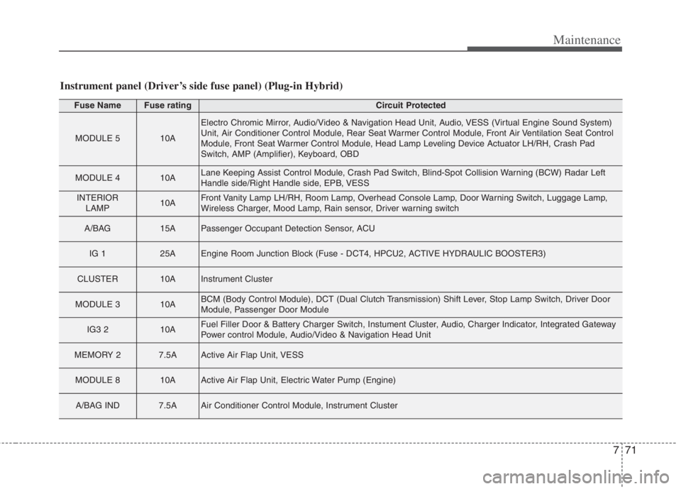
Instrument panel (Driver’s side fuse panel) (Plug-in Hybrid)
Fuse NameFuse ratingCircuit Protected
MODULE 510A
Electro Chromic Mirror, Audio/Video & Navigation Head Unit, Audio, VESS (Virtual Engine Sound System)
Unit, Air Conditioner Control Module, Rear Seat Warmer Control Module, Front Air Ventilation Seat Control
Module, Front Seat Warmer Control Module, Head Lamp Leveling Device Actuator LH/RH, Crash Pad
Switch, AMP (Amplifier), Keyboard, OBD
MODULE 410ALane Keeping Assist Control Module, Crash Pad Switch, Blind-Spot Collision Warning (BCW) Radar Left
Handle side/Right Handle side, EPB, VESS
INTERIOR
LAMP10AFront Vanity Lamp LH/RH, Room Lamp, Overhead Console Lamp, Door Warning Switch, Luggage Lamp,
Wireless Charger, Mood Lamp, Rain sensor, Driver warning switch
A/BAG15APassenger Occupant Detection Sensor, ACU
IG 125AEngine Room Junction Block (Fuse - DCT4, HPCU2, ACTIVE HYDRAULIC BOOSTER3)
CLUSTER10AInstrument Cluster
MODULE 310ABCM (Body Control Module), DCT (Dual Clutch Transmission) Shift Lever, Stop Lamp Switch, Driver Door
Module, Passenger Door Module
IG3 210AFuel Filler Door & Battery Charger Switch, Instument Cluster, Audio, Charger Indicator, Integrated Gateway
Power control Module, Audio/Video & Navigation Head Unit
MEMORY 27.5AActive Air Flap Unit, VESS
MODULE 810AActive Air Flap Unit, Electric Water Pump (Engine)
A/BAG IND7.5AAir Conditioner Control Module, Instrument Cluster
Page 618 of 684

Maintenance
76 7
Engine room compartment fuse panel (Hybrid)
Fuse NameFuse ratingCircuit Protected
MULTI FUSE
B+ 560AFuse - BATTERY C/FAN, HORN, ECU2, Engine Control Relay
B+ 260AInstrument Panel Junction Block (Fuse - S/HEATER (REAR))
B+ 360AInstrument Panel Junction Block
B+ 450AInstrument Panel Junction Block (Fuse - BATTERY MANAGEMENT, P/WINDOW (LH), P/WIN-
DOW (RH), TAIL GATE OPEN, SUNROOF, AMP, S/HEATER (FRT), P/SEAT (DRV))
COOLING FAN60ACooling Fan Relay
REAR HEATED50ARear Heated Relay
BLOWER40ABlower Relay
IG 140A[Without Smart Key] Ignition Switch, [With Smart Key] PDM1 (ACC) Relay, PDM2 (IG1) Relay
IG 240A[Without Smart Key] Ignition Switch, [With Smart Key] PDM3 (IG2) Relay
MDPS80AMDPS (Motor Driven Power Steering) Unit
PTC
HEATER 150APTC Heater 1 Relay
PTC
HEATER 250APTC Heater 2 Relay
CLUTCH
ACTUATOR40AClutch Actuator (HEV)
MAIN150AFuse - H/LAMP HI, INVERTER, ACTIVE HYDRAULIC BOOSTER1, ACTIVE HYDRAULIC
BOOSTER2, WIPER RR, EPB1, EPB2
POWE
OUTLET 140APower outlet Relay
Page 619 of 684

777
Maintenance
Fuse NameFuse ratingCircuit Protected
FUSE
POWER
OUTLET 320APower Outlet #2
POWER
OUTLET 220APower Outlet #1
DCT 315ATCM (Transmission Control Module)
HPCU 110AHPCU (Hybrid Power Control Unit)
EWP10AElectric Water Pump (Engine)
FUEL PUMP20AFuel Pump Relay
B + 140AInstrument Panel Junction Block (Fuse - BRAKE SWITCH, PDM1, PDM2, MODULE1, DOOR
LOCK, Leak Current Autocut Device)
DCT 240ATCM (Transmission Control Module)
DCT 140ATCM (Transmission Control Module)
WIPER RR15AWiper RR Relay
H/LAMP HI10AH/Lamp HI Relay
ACTIVE
HYDRAULIC
BOOTER 140AIntegrated Brake Actuation Unit
Page 622 of 684

Maintenance
80 7
Engine room compartment fuse panel (Plug-in Hybrid)
Fuse NameFuse ratingCircuit Protected
MULTI FUSE
B+ 560AFuse - BATTERY C/FAN, HORN, ECU2, Engine Control Relay
B+ 260AInstrument Panel Junction Block (Fuse - S/HEATER (REAR))
B+ 360AInstrument Panel Junction Block
B+ 450AInstrument Panel Junction Block (Fuse - BATTERY MANAGEMENT, P/WINDOW (LH), P/WIN-
DOW (RH), TAIL GATE OPEN, SUNROOF, AMP, S/HEATER (FRT), P/SEAT (DRV), IG3 1,
OBC, AMS)
COOLING FAN60ACooling Fan Relay
REAR HEATED50ARear Heated Relay
BLOWER40ABlower Relay
IG 140A[Without Smart Key] Ignition Switch, [With Smart Key] PDM1 (ACC) Relay, PDM2 (IG1) Relay
IG 240A[Without Smart Key] Ignition Switch, [With Smart Key] PDM3 (IG2) Relay
MDPS80AMDPS (Motor Driven Power Steering) Unit
PTC
HEATER 150APTC Heater 1 Relay
PTC
HEATER 250APTC Heater 2 Relay
CLUTCH
ACTUATOR40AClutch Actuator (PHEV)
MAIN150AFuse - H/LAMP HI, INVERTER, ACTIVE HYDRAULIC BOOSTER1, ACTIVE HYDRAULIC
BOOSTER2, WIPER RR, EPB1, EPB2
Page 623 of 684

781
Maintenance
Fuse NameFuse ratingCircuit Protected
MULTI FUSEPOWE
OUTLET 140APower outlet Relay
FUSE
POWER
OUTLET 320APower Outlet #2
POWER
OUTLET 220APower Outlet #1
DCT 315ATCM (Transmission Control Module)
HPCU 110AHPCU (Hybrid Power Control Unit)
EWP10AElectric Water Pump (Engine)
FUEL PUMP20AFuel Pump Relay
B + 140AInstrument Panel Junction Block (Fuse - BRAKE SWITCH, PDM1, PDM2, MODULE1, DOOR
LOCK, Leak Current Autocut Device)
DCT 240ATCM (Transmission Control Module)
DCT 140ATCM (Transmission Control Module)
WIPER RR15AWiper RR Relay
H/LAMP HI10AH/Lamp HI Relay
ACTIVE
HYDRAULIC
BOOTER 140AIntegrated Brake Actuation Unit
Page 679 of 684

Index
6I
If the engine stalls while driving. . . . . . . . . . . . . . . . 6-3
If you have a flat tire while driving . . . . . . . . . . . . . 6-3
Infotainment system . . . . . . . . . . . . . . . . . . . . . . . . . . 4-185
Antenna . . . . . . . . . . . . . . . . . . . . . . . . . . . . . . . . . 4-185
How vehicle radio works . . . . . . . . . . . . . . . . . . . . 4-186
USB port. . . . . . . . . . . . . . . . . . . . . . . . . . . . . . . . . 4-185
Instrument cluster . . . . . . . . . . . . . . . . . . . . . . . . . . . . . 4-68
Dual clutch transmission shift indicator . . . . . . . . . 4-76
Gauges . . . . . . . . . . . . . . . . . . . . . . . . . . . . . . . . . . . 4-70
Instrument Cluster Control. . . . . . . . . . . . . . . . . . . . 4-70
Instrument panel overview . . . . . . . . . . . . . . . . . . . . . . . 2-5
Interior features. . . . . . . . . . . . . . . . . . . . . . . . . . . . . . 4-170
AC inverter . . . . . . . . . . . . . . . . . . . . . . . . . . . . . . . 4-175
Air ventilation seat . . . . . . . . . . . . . . . . . . . . . . . . . 4-172
Cargo security screen . . . . . . . . . . . . . . . . . . . . . . . 4-182
Clothes hanger . . . . . . . . . . . . . . . . . . . . . . . . . . . . 4-180
Cup holder . . . . . . . . . . . . . . . . . . . . . . . . . . . . . . . 4-170
Floor mat anchor(s) . . . . . . . . . . . . . . . . . . . . . . . . 4-180
Luggage net holder. . . . . . . . . . . . . . . . . . . . . . . . . 4-181
Power outlet . . . . . . . . . . . . . . . . . . . . . . . . . . . . . . 4-173
Seat warmer . . . . . . . . . . . . . . . . . . . . . . . . . . . . . . 4-170
Sun visor. . . . . . . . . . . . . . . . . . . . . . . . . . . . . . . . . 4-173
USB charger . . . . . . . . . . . . . . . . . . . . . . . . . . . . . . 4-174
Wireless smart phone charging system . . . . . . . . . 4-176
Interior lights . . . . . . . . . . . . . . . . . . . . . . . . . . . . . . . 4-143
Automatic turn off function . . . . . . . . . . . . . . . . . . 4-143
Liftgate room lamp. . . . . . . . . . . . . . . . . . . . . . . . . 4-145
Map lamp . . . . . . . . . . . . . . . . . . . . . . . . . . . . . . . 4-143Room lamp . . . . . . . . . . . . . . . . . . . . . . . . . . . . . . . 4-144
Vanity mirror lamp . . . . . . . . . . . . . . . . . . . . . . . . . 4-145
Interior overview. . . . . . . . . . . . . . . . . . . . . . . . . . . . . . . 2-4
Key positions . . . . . . . . . . . . . . . . . . . . . . . . . . . . . . . . . 5-7
Ignition switch position . . . . . . . . . . . . . . . . . . . . . . . 5-7
Illuminated ignition switch . . . . . . . . . . . . . . . . . . . . 5-7
Starting the hybrid system . . . . . . . . . . . . . . . . . . . . . 5-9
Lane Following Assist (LFA) . . . . . . . . . . . . . . . . . . . 5-132
Lane Following Assist malfunction . . . . . . . . . . . . 5-136
Lane Following Assist operation . . . . . . . . . . . . . . 5-133
Limitation of Lane Following Assist . . . . . . . . . . . 5-136
Lane Keeping Assist (LKA) . . . . . . . . . . . . . . . . . . . . . 5-71
Lane Keeping Assist activation . . . . . . . . . . . . . . . . 5-74
Lane Keeping Assist malfunction . . . . . . . . . . . . . . 5-77
Lane Keeping Assist operation . . . . . . . . . . . . . . . . 5-72
Lane Keeping Assist setting . . . . . . . . . . . . . . . . . . . 5-73
LCD Display . . . . . . . . . . . . . . . . . . . . . . . . . . . . . . . . . 4-78
LCD Display Control . . . . . . . . . . . . . . . . . . . . . . . . 4-78
LCD Display Modes . . . . . . . . . . . . . . . . . . . . . . . . 4-79
Trip modes (Trip computer) . . . . . . . . . . . . . . . . . . . 4-91
Warning messages . . . . . . . . . . . . . . . . . . . . . . . . . . 4-96
K
L