2022 HYUNDAI KONA fuel
[x] Cancel search: fuelPage 542 of 579
Maintenance
9-56
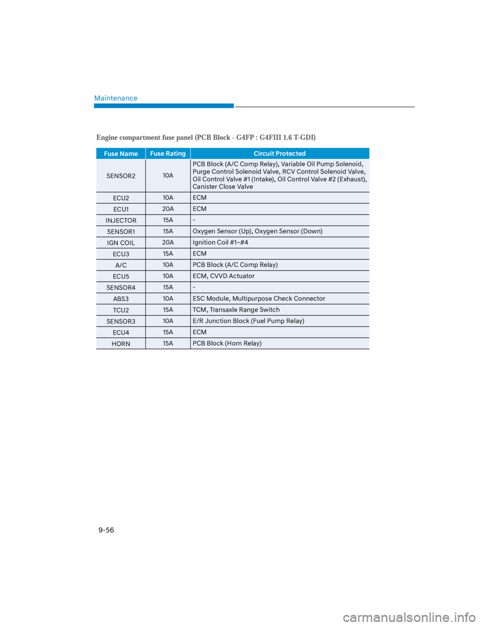
Fuse NameFuse Rating Circuit Protected
SENSOR210A
PCB Block (A/C Comp Relay), Variable Oil Pump Solenoid,
Purge Control Solenoid Valve, RCV Control Solenoid Valve,
Oil Control Valve #1 (Intake), Oil Control Valve #2 (Exhaust),
Canister Close Valve
ECU210A ECM
ECU120A ECM
INJECTOR15A -
SENSOR115A Oxygen Sensor (Up), Oxygen Sensor (Down)
IGN COIL20A Ignition Coil #1~#4
ECU315A ECM
A/C10A PCB Block (A/C Comp Relay)
ECU510A ECM, CVVD Actuator
SENSOR415A -
ABS310A ESC Module, Multipurpose Check Connector
TCU215A TCM, Transaxle Range Switch
SENSOR310A E/R Junction Block (Fuel Pump Relay)
ECU415A ECM
HORN15A PCB Block (Horn Relay)
Page 543 of 579
09
9-57
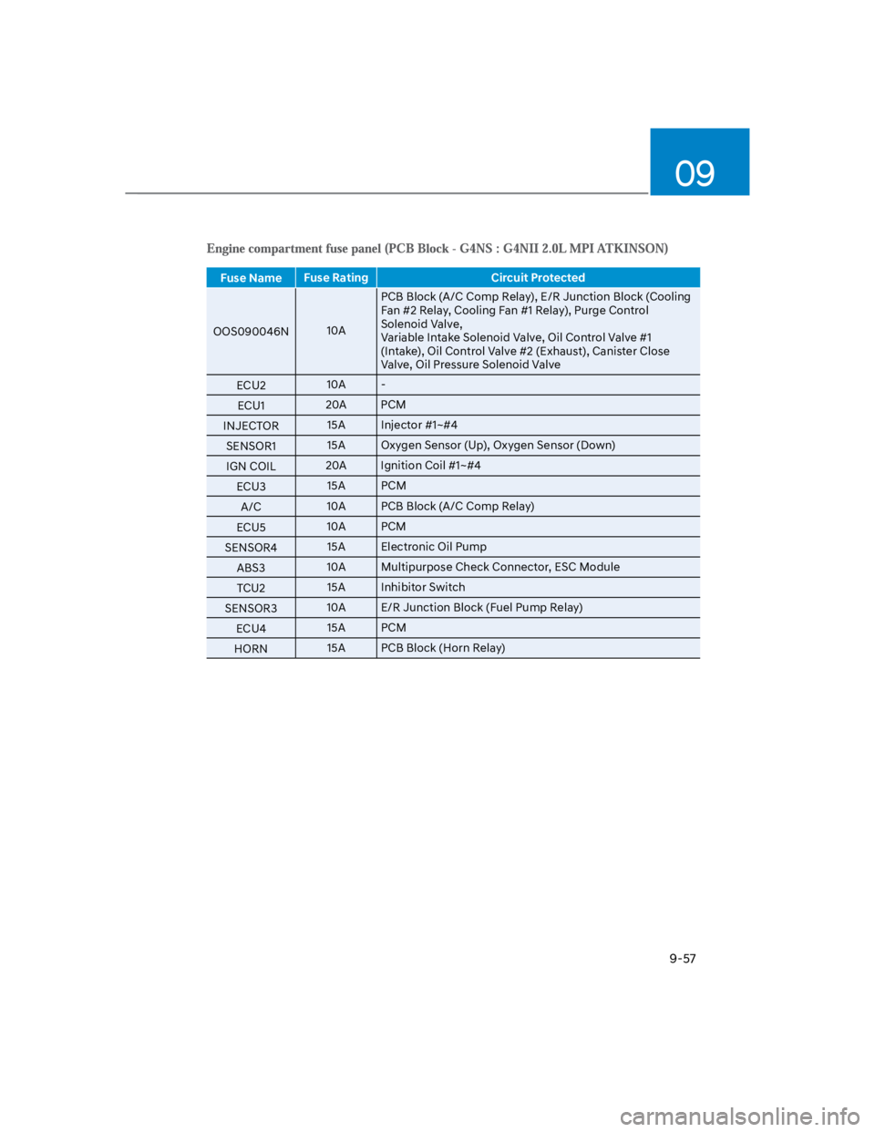
Fuse NameFuse Rating Circuit Protected
OOS090046N10A
PCB Block (A/C Comp Relay), E/R Junction Block (Cooling
Fan #2 Relay, Cooling Fan #1 Relay), Purge Control
Solenoid Valve,
Variable Intake Solenoid Valve, Oil Control Valve #1
(Intake), Oil Control Valve #2 (Exhaust), Canister Close
Valve, Oil Pressure Solenoid Valve
ECU210A -
ECU120A PCM
INJECTOR15A Injector #1~#4
SENSOR115A Oxygen Sensor (Up), Oxygen Sensor (Down)
IGN COIL20A Ignition Coil #1~#4
ECU315A PCM
A/C10A PCB Block (A/C Comp Relay)
ECU510A PCM
SENSOR415A Electronic Oil Pump
ABS310A Multipurpose Check Connector, ESC Module
TCU215A Inhibitor Switch
SENSOR310A E/R Junction Block (Fuel Pump Relay)
ECU415A PCM
HORN15A PCB Block (Horn Relay)
Page 557 of 579

09
9-71
Bright-metal maintenance
To remove road tar and insects, use
a tar remover, not a scraper or other
sharp object.
To protect the surfaces of bright metal
parts from corrosion, apply a coating
of wax or chrome preservative and rub
to a high luster.
During winter weather or in coastal
areas, cover the bright metal parts
with a heavier coating of wax or
preservative. If necessary, coat the
parts with non-corrosive petroleum
jelly or other protective compound.
Underbody maintenance
Corrosive materials used for ice and
snow removal and dust control may
collect on the underbody. If these
materials are not removed, accelerated
rusting can occur on underbody parts
such as the fuel lines, frame, floor pan
and exhaust system, even though they
have been treated with rust protection.
Thoroughly flush the vehicle underbody
and wheel openings with lukewarm or
cold water once a month, after off-road
driving and at the end of each winter. Pay
special attention to these areas because
it is difficult to see all the mud and dirt.
It will do more harm than good to wet
down the road grime without removing
it. The lower edges of doors, rocker
panels, and frame members have drain
holes that should not be allowed to clog
with dirt; trapped water in these areas
can cause rusting.
WARNING
After washing the vehicle, test the
brakes while driving slowly to see if
they have been affected by water. If
braking performance is impaired, dry
the brakes by applying them lightly
while maintaining a slow forward
speed.
Aluminum wheel maintenance
The aluminum wheels are coated with a
clear protective finish.
Do not use abrasive cleaner, polishing
compound, solvent, or wire brushes
on aluminum wheels.
Clean the wheel when it has cooled.
Use only a mild soap or neutral
detergent, and rinse thoroughly with
water. Also, clean the wheels after
driving on salted roads.
Do not wash the wheels with high-
speed car wash brushes.
Do not use any cleaners containing
acid or alkaline detergents.
Page 563 of 579
09
9-77
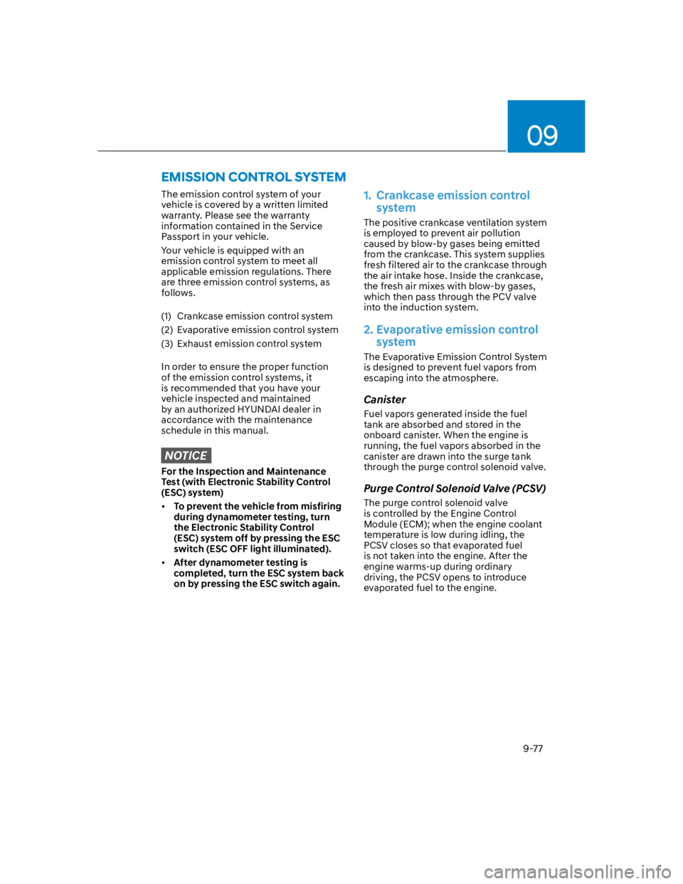
The emission control system of your
vehicle is covered by a written limited
warranty. Please see the warranty
information contained in the Service
Passport in your vehicle.
Your vehicle is equipped with an
emission control system to meet all
applicable emission regulations. There
are three emission control systems, as
follows.
(1) Crankcase emission control system
(2) Evaporative emission control system
(3) Exhaust emission control system
In order to ensure the proper function
of the emission control systems, it
is recommended that you have your
vehicle inspected and maintained
by an authorized HYUNDAI dealer in
accordance with the maintenance
schedule in this manual.
NOTICE
For the Inspection and Maintenance
Test (with Electronic Stability Control
(ESC) system)
To prevent the vehicle from misfiring
during dynamometer testing, turn
the Electronic Stability Control
(ESC) system off by pressing the ESC
switch (ESC OFF light illuminated).
After dynamometer testing is
completed, turn the ESC system back
on by pressing the ESC switch again.
1. Crankcase emission control
system
The positive crankcase ventilation system
is employed to prevent air pollution
caused by blow-by gases being emitted
from the crankcase. This system supplies
fresh filtered air to the crankcase through
the air intake hose. Inside the crankcase,
the fresh air mixes with blow-by gases,
which then pass through the PCV valve
into the induction system.
2. Evaporative emission control
system
The Evaporative Emission Control System
is designed to prevent fuel vapors from
escaping into the atmosphere.
Canister
Fuel vapors generated inside the fuel
tank are absorbed and stored in the
onboard canister. When the engine is
running, the fuel vapors absorbed in the
canister are drawn into the surge tank
through the purge control solenoid valve.
Purge Control Solenoid Valve (PCSV)
The purge control solenoid valve
is controlled by the Engine Control
Module (ECM); when the engine coolant
temperature is low during idling, the
PCSV closes so that evaporated fuel
is not taken into the engine. After the
engine warms-up during ordinary
driving, the PCSV opens to introduce
evaporated fuel to the engine.
EMISSION CONTROL SYSTEM
Page 565 of 579
09
9-79
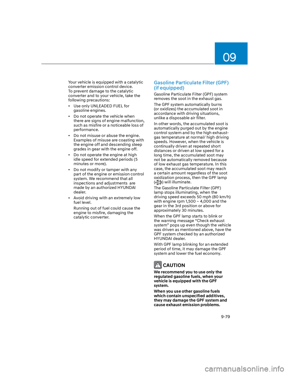
Your vehicle is equipped with a catalytic
converter emission control device.
To prevent damage to the catalytic
converter and to your vehicle, take the
following precautions:
Use only UNLEADED FUEL for
gasoline engines.
Do not operate the vehicle when
there are signs of engine malfunction,
such as misfire or a noticeable loss of
performance.
Do not misuse or abuse the engine.
Examples of misuse are coasting with
the engine off and descending steep
grades in gear with the engine off.
Do not operate the engine at high
idle speed for extended periods (5
minutes or more).
Do not modify or tamper with any
part of the engine or emission control
system. We recommend that all
inspections and adjustments are
made by an authorized HYUNDAI
dealer.
Avoid driving with an extremely low
fuel level.
Running out of fuel could cause the
engine to misfire, damaging the
catalytic converter.
Gasoline Particulate Filter (GPF)
(if equipped)
Gasoline Particulate Filter (GPF) system
removes the soot in the exhaust gas.
The GPF system automatically burns
(or oxidizes) the accumulated soot in
accordance with driving situations,
unlike a disposable air filter.
In other words, the accumulated soot is
automatically purged out by the engine
control system and by the high exhaust-
gas temperature at normal/ high driving
speeds. However, when the vehicle is
continually driven at repeated short
distances or driven at low speed for a
long time, the accumulated soot may
not be automatically removed because
of low exhaust gas temperature. In this
case, the accumulated soot may reach
a certain amount regardless of the soot
oxidization process, then the GPF lamp
() will illuminate.
The Gasoline Particulate Filter (GPF)
lamp stops illuminating, when the
driving speed exceeds 50 mph (80 km/h)
with engine rpm 1,500 ~ 4,000 and the
gear in the 3rd position or above for
approximately 30 minutes.
When the GPF lamp starts to blink or
the warning message “Check exhaust
system” pops up even though the vehicle
was driven as mentioned above, have the
GPF system checked by an authorized
HYUNDAI dealer.
With GPF lamp blinking for an extended
period of time, it may damage the GPF
system and lower the fuel economy.
CAUTION
We recommend you to use only the
regulated gasoline fuels, when your
vehicle is equipped with the GPF
system.
When you use other gasoline fuels
which contain unspecified additives,
they may damage the GPF system and
cause exhaust emission problems.
Page 571 of 579

I
I-5
Engine Start/Stop button........................................................................................ 6-8
Engine Stop/Start button positions ..................................................................... 6-9
Remote start...................................................................................................... 6-12
Starting the engine............................................................................................ 6-10
Turning off the engine ...................................................................................... 6-11
Explanation of scheduled maintenance items ...................................................... 9-13
Fuel filter (for gasoline engine)........................................................................ 9-13
Intelligent variable transmission fluid ............................................................. 9-14
Parking brake.................................................................................................... 9-14
Propeller shaft .................................................................................................. 9-14
Exterior features......................................................................................... 5-61,5-115
Fuel filler door.................................................................................................. 5-64
Hood ................................................................................................................. 5-61
Liftgate ............................................................................................................. 5-62
Roof side rails................................................................................................. 5-115
Exterior overview (I) ............................................................................................. 2-2
Exterior overview (II) ............................................................................................ 2-4
F
Foreword................................................................................................................ 1-2
Forward Collision–Avoidance Assist (FCA) (front view camera only) ................ 7-2
Forward Collision-Avoidance Assist malfunction and limitations .................... 7-7
Forward Collision-Avoidance Assist operation.................................................. 7-5
Forward Collision-Avoidance Assist settings..................................................... 7-3
Forward Collision–Avoidance Assist (FCA) (Sensor fusion) ............................ 7-14
Forward Collision-Avoidance Assist malfunction and limitations .................. 7-21
Forward Collision-Avoidance Assist operation................................................ 7-18
Forward Collision-Avoidance Assist settings................................................... 7-16
Four wheel drive (4WD)...................................................................................... 6-46
Emergency precautions .................................................................................... 6-51
Four Wheel Drive (4WD) operation ................................................................ 6-47
Reducing the risk of a rollover ......................................................................... 6-52
Fuel requirements .................................................................................................. 1-5
Gasoline engine .................................................................................................. 1-5
Fuses .................................................................................................................... 9-45
Engine compartment panel fuse replacement................................................... 9-47
Fuse/relay panel description............................................................................. 9-49
Instrument panel fuse replacement................................................................... 9-46