Page 23 of 579
Vehicle Information, Consumer Information and Reporting Safety Defects
2-10
Light Bulb Bulb Type Wattage
Front
Headlamp
Low (Type A) 9005HL+ 60W
High (Type A) 9005HL+ 60W
Low (Type B) LED LED
High (Type B) LED LED
Turn signal lamp P28/8W 28W
Side marker LED LED
Turn signal lamp (Outside mirror) LED LED
Daytime running lamp (DRL) /
position lampLED LED
Fog lamp HB4 55W
Rear
Rear combination
lamp
Stop/Tail
(Type A)P21/5WSTOP : 21,
TAIL : 5
Tail (Type A) W5W 5W
Stop/Tail
(Type B)LED LED
Turn signalTYPE A:PY21W,
TYPE B:LED
TYPE A:21W,
TYPE B:LED
Reverse lamp P21W 21
Fog lamp PR21W 21
High mounted stop lamp LED LED
Side markerTYPE A:W5W,
TYPE B:LED
TYPE A:5W,
TYPE B:LED
License plate lamp W5W 5
Interior
Map lamp W10W 10
Room lamp (with sunroof) FESTOON 8
Room lamp (without sunroof) FESTOON 10
Sunvisor lamp FESTOON 5
Tailgate room lamp FESTOON 10
Glove box lamp FESTOON 5
BULB WATTAGE
Page 286 of 579

06
6-29
If there is a problem with the brake
pedal while driving, emergency braking
is possible by pulling up and holding
the EPB switch. Braking is possible only
while you are holding the EPB switch.
However, braking distance will be longer
than normal.
WARNING
To reduce the risk of SERIOUS INJURY
or DEATH, do not operate the EPB
while the vehicle is moving except
in an emergency situation. It could
damage the brake system and lead to
an accident.
Information
NOTICE
If you continuously notice a noise or
burning smell when the EPB is used for
emergency braking, have the system
checked by an authorized HYUNDAI
dealer.
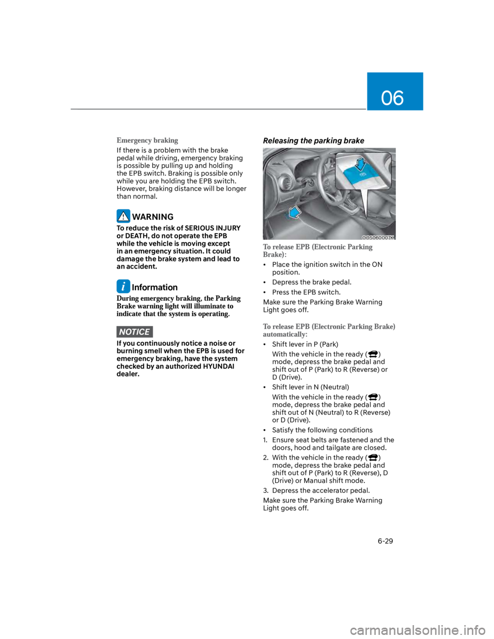
Releasing the parking brake
OOS060007K
Place the ignition switch in the ON
position.
Depress the brake pedal.
Press the EPB switch.
Make sure the Parking Brake Warning
Light goes off.
Shift lever in P (Park)
With the vehicle in the ready ()
mode, depress the brake pedal and
shift out of P (Park) to R (Reverse) or
D (Drive).
Shift lever in N (Neutral)
With the vehicle in the ready ()
mode, depress the brake pedal and
shift out of N (Neutral) to R (Reverse)
or D (Drive).
Satisfy the following conditions
1. Ensure seat belts are fastened and the
doors, hood and tailgate are closed.
2. With the vehicle in the ready ()
mode, depress the brake pedal and
shift out of P (Park) to R (Reverse), D
(Drive) or Manual shift mode.
3. Depress the accelerator pedal.
Make sure the Parking Brake Warning
Light goes off.
Page 536 of 579

Maintenance
9-50
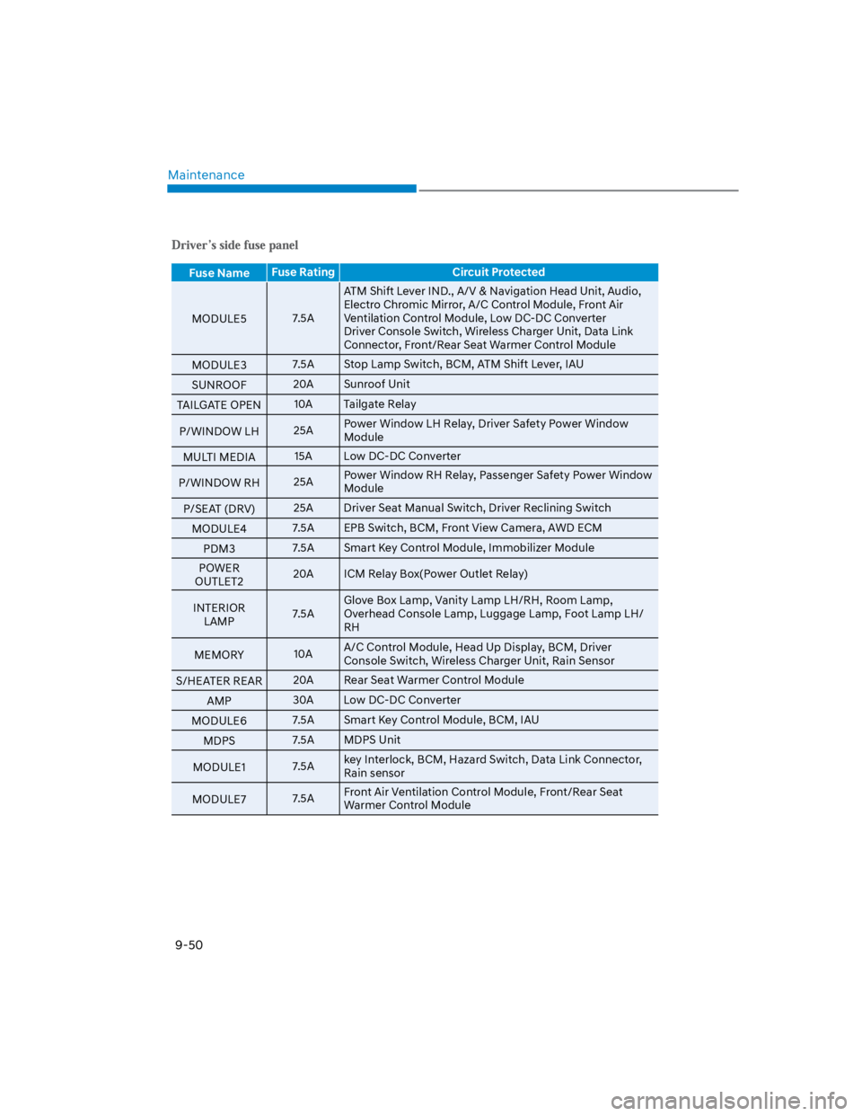
Fuse NameFuse Rating Circuit Protected
MODULE57.5A
ATM Shift Lever IND., A/V & Navigation Head Unit, Audio,
Electro Chromic Mirror, A/C Control Module, Front Air
Ventilation Control Module, Low DC-DC Converter
Driver Console Switch, Wireless Charger Unit, Data Link
Connector, Front/Rear Seat Warmer Control Module
MODULE37.5A Stop Lamp Switch, BCM, ATM Shift Lever, IAU
SUNROOF20A Sunroof Unit
TAILGATE OPEN10A Tailgate Relay
P/WINDOW LH25APower Window LH Relay, Driver Safety Power Window
Module
MULTI MEDIA15A Low DC-DC Converter
P/WINDOW RH25APower Window RH Relay, Passenger Safety Power Window
Module
P/SEAT (DRV)25A Driver Seat Manual Switch, Driver Reclining Switch
MODULE47.5A EPB Switch, BCM, Front View Camera, AWD ECM
PDM37.5A Smart Key Control Module, Immobilizer Module
POWER
OUTLET220A ICM Relay Box(Power Outlet Relay)
INTERIOR
LAMP7.5A
Glove Box Lamp, Vanity Lamp LH/RH, Room Lamp,
Overhead Console Lamp, Luggage Lamp, Foot Lamp LH/
RH
MEMORY10AA/C Control Module, Head Up Display, BCM, Driver
Console Switch, Wireless Charger Unit, Rain Sensor
S/HEATER REAR20A Rear Seat Warmer Control Module
AMP30A Low DC-DC Converter
MODULE67.5A Smart Key Control Module, BCM, IAU
MDPS7.5A MDPS Unit
MODULE17.5Akey Interlock, BCM, Hazard Switch, Data Link Connector,
Rain sensor
MODULE77.5AFront Air Ventilation Control Module, Front/Rear Seat
Warmer Control Module
Page 540 of 579

Maintenance
9-54
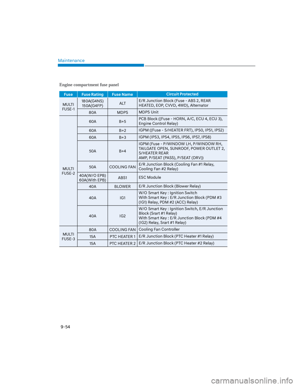
Fuse Fuse Rating Fuse NameCircuit Protected
MULTI
FUSE-1
180A(G4NS)
150A(G4FP)ALTE/R Junction Block (Fuse - ABS 2, REAR
HEATED, EOP, CVVD, 4WD), Alternator
80A MDPSMDPS Unit
MULTI
FUSE-2
60A B+5PCB Block ((Fuse - HORN, A/C, ECU 4, ECU 3),
Engine Control Relay)
60A B+2IGPM ((Fuse - S/HEATER FRT), IPS0, IPS1, IPS2)
60A B+3IGPM (IPS3, IPS4, IPS5, IPS6, IPS7, IPS8)
50A B+4
IGPM (Fuse - P/WINDOW LH, P/WINDOW RH,
TAILGATE OPEN, SUNROOF, POWER OUTLET 2,
S/HEATER REAR
AMP, P/SEAT (PASS), P/SEAT (DRV))
50A COOLING FANE/R Junction Block (Cooling Fan #1 Relay,
Cooling Fan #2 Relay)
40A(W/O EPB)
60A(With EPB)ABS1ESC Module
40A BLOWERE/R Junction Block (Blower Relay)
40A IG1
W/O Smart Key : Ignition Switch
With Smart Key : E/R Junction Block (PDM #3
(IG1) Relay, PDM #2 (ACC) Relay)
40A IG2
W/O Smart Key : Ignition Switch, E/R Junction
Block (Srart #1 Relay)
With Smart Key : E/R Junction Block (PDM #4
(IG2) Relay, Srart #1 Relay)
MULTI
FUSE-3
80A COOLING FANCooling Fan Controller
15A PTC HEATER 1E/R Junction Block (PTC Heater #1 Relay)
15A PTC HEATER 2E/R Junction Block (PTC Heater #2 Relay)
Page 550 of 579
Maintenance
9-64
OOS077066L
1. Turn off the engine.
2. Open the tailgate.
3. Loosen the lamp assembly retaining
screws with a cross-tip screwdriver.
OOS077068L
4. Remove the rear combination lamp
assembly from the body of the
vehicle.
5. Remove the socket from the
assembly by turning the socket
counterclockwise until the tabs on
the socket align with the slots on the
assembly.
6. Remove the bulb from the socket
by pressing it in and rotating it
counterclockwise until the tabs on the
bulb align with the slots in the socket.
Pull the bulb out of the socket.
7. Insert a new bulb by inserting it into
the socket and rotating it until it locks
into place.
8. Install the socket into the assembly by
aligning the tabs on the socket with
the slots in the assembly. Push the
socket into the assembly and turn the
socket clockwise.
9. 9. Reinstall the lamp assembly to the
body of the vehicle.
Page 551 of 579

09
9-65
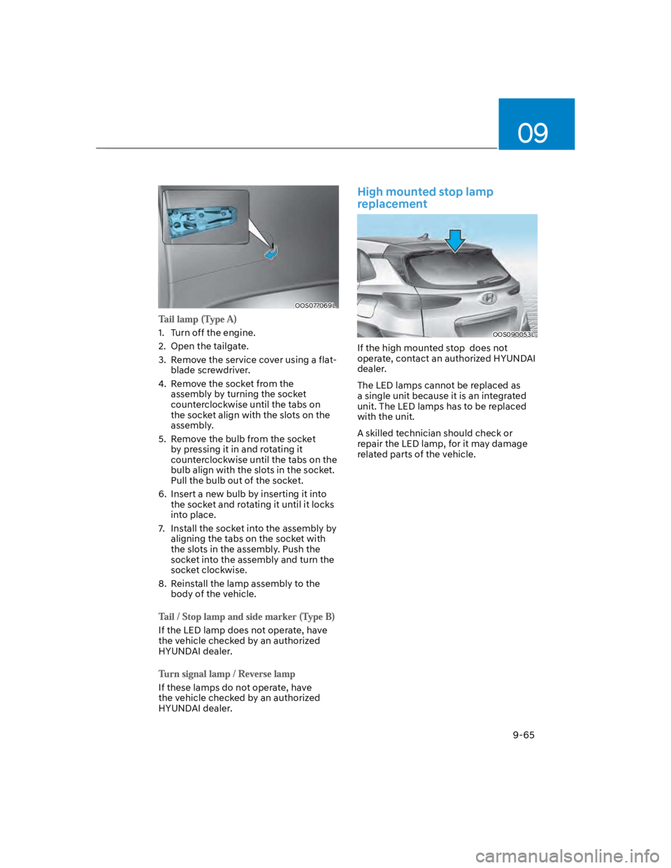
OOS077069L
1. Turn off the engine.
2. Open the tailgate.
3. Remove the service cover using a flat-
blade screwdriver.
4. Remove the socket from the
assembly by turning the socket
counterclockwise until the tabs on
the socket align with the slots on the
assembly.
5. Remove the bulb from the socket
by pressing it in and rotating it
counterclockwise until the tabs on the
bulb align with the slots in the socket.
Pull the bulb out of the socket.
6. Insert a new bulb by inserting it into
the socket and rotating it until it locks
into place.
7. Install the socket into the assembly by
aligning the tabs on the socket with
the slots in the assembly. Push the
socket into the assembly and turn the
socket clockwise.
8. Reinstall the lamp assembly to the
body of the vehicle.
If the LED lamp does not operate, have
the vehicle checked by an authorized
HYUNDAI dealer.
If these lamps do not operate, have
the vehicle checked by an authorized
HYUNDAI dealer.
High mounted stop lamp
replacement
OOS090053L
If the high mounted stop does not
operate, contact an authorized HYUNDAI
dealer.
The LED lamps cannot be replaced as
a single unit because it is an integrated
unit. The LED lamps has to be replaced
with the unit.
A skilled technician should check or
repair the LED lamp, for it may damage
related parts of the vehicle.