Page 510 of 657

508
Driving
Braking
Brake System
Use the parking brake to keep the vehicle stationary when parked. When the
parking brake is applied, you can ma nually or automatically release it.
■To apply
The electric parking brake can be applied any
time the vehicle has battery, no matter which
position the power mode is in.
Pull the electric parking brake switch up gently
and securely. u The indicator in the switch comes on.
u The parking brake and brake system
indicator (red) comes on.
■To release
The power mode must be in ON in order to
release the electric parking brake.
1. Depress the brake pedal.
2. Press the electric parking brake switch.
u The indicator in the switch goes off.
u The parking brake and brake system
indicator (red) goes off.
Manually releasing the parking brake using
the switch helps your ve hicle start slowly and
smoothly when facing downhill on steep hills.
■Parking Brake1 Braking
When you depress the brak e pedal, you may hear a
whirring sound from the engine compartment. This is
because the brake system is in operation, and it is
normal.
1 Parking Brake
You may hear the electric parking brake system
motor operating from the re ar wheel area when you
apply or release the parking brake. This is normal.
The brake pedal may slightly move due to the electric
parking brake system opera tion when you apply or
release the parking br ake. This is normal.
You cannot apply or release the parking brake if the
battery goes dead. 2 If the Battery Is Dead P. 606
If you pull up and hold the electric parking brake
switch while driving, the brakes on all four
wheels are applied by the VSA ® system until the
vehicle comes to a stop. The electric parking
brake then applies, and the switch should be
released.
Electric Parking Brake Switch
Electric Parking Brake Switch
Page 552 of 657

550
uuMaintenance Under the Hood uOpening the Hood
Maintenance
Opening the Hood
1. Park the vehicle on a level surface, and set
the parking brake.
2. Pull the hood release handle under the
driver’s side lower corner of the dashboard.
u The hood will pop up slightly.
3. Push the hood latch lever (located under
the front edge of the hood to the center) to
the side and raise the hood. Once you have
raised the hood slightly, you can release the
lever.
4. Remove the support rod from the clamp
using the grip. Mount the support rod in
the hood.
When closing, remove the support rod, and
stow it in the clamp, then gently lower the
hood. Remove your hand at a height of
approximately 12 inches (30 cm) and let the
hood close.1 Opening the Hood
NOTICE
Do not open the hood when the wiper arms are
raised.
The hood will strike the wipe rs, resulting in possible
damage to the hood and/or the wipers.
Do not press the engine cover forcibly. This may
damage the engine cover and component parts.
When closing the hood, check that the hood is
securely latched.
If the hood latch lever moves stiffly, or if you can
open the hood without lifti ng the lever, the latch
mechanism should be cl eaned and lubricated.
Do not open the hood while the Auto Idle Stop
function is activated.
3WARNING
The hood support rod can become very hot
due to heat fr om the engine.
To ensure against po ssible burns, do not
handle the metal section of the rod:
Use the foam grip instead.
2.0 L engine models
Models with Auto Idle Stop
Hood Release Handle
Pull
Lever
Support Rod
Grip
Clamp
Page 556 of 657
554
uuMaintenance Under the Hood uAdding Engine Oil
Maintenance
Adding Engine Oil
1. Unscrew and remove the engine oil fill cap.
2. Add oil slowly.
3. Reinstall the engine oil fill cap, and tighten
it securely.
4. Wait for three minutes and recheck the
engine oil dipstick.1Adding Engine Oil
NOTICE
Do not fill the engine oil above the upper mark.
Overfilling the engine oil may result in leaks and
engine damage.
If any oil spills, wipe it away immediately. Spilled oil
may damage the engine compartment components.
1.5 L engine models
2.0 L engine models
Engine Oil Fill Cap
Engine Oil Fill Cap
Page 560 of 657

uuMaintenance Under the Hood uChanging the Engine Oil and Oil Filter
558
Maintenance
6. Remove the oil filter and dispose of the
remaining oil.
7. Check that the filter ga sket is not stuck to
the engine contact surface.
u If it is stuck, you must detach it.
8. Wipe away dirt and dust adhering to the
contact surface of the engine block, and
install a new oil filter.
u Apply a light coat of new engine oil to
the filter gasket.
9. Put a new washer on the drain bolt, then
reinstall the drain bolt.
u Tightening torque:
30 lbf∙ft (40 N∙m, 4.0 kgf∙m)
10. Pour the recommended engine oil into the
engine.
u Engine oil change capacity (including
filter):
3.7 US qt (3.5 L)
5.0 US qt (4.8 L)
11. Reinstall the engine oi l fill cap securely and
start the engine.
12. Run the engine for a few minutes, and
then check that there is no leak from the
drain bolt or oil filter.
13. Stop the engine, wait for three minutes,
and then check the oil level on the dipstick.
u If necessary, add more engine oil.1Changing the Engine Oil and Oil Filter
You will need a special wrench to replace the oil
filter. You can buy this wrench from a dealer.
When installing the new oil filter, follow the
instructions supplied with the oil filter.
Reinstall the engine oil fill cap. Start the engine. If the
low oil pressure warning appears, turn off the
engine, and check your work.1.5 L engine models
2.0 L engine models
Oil Filter
Oil Filter1.5 L engine models
2.0 L engine models
Page 591 of 657

589
uuCleaning uInterior Care
Maintenance
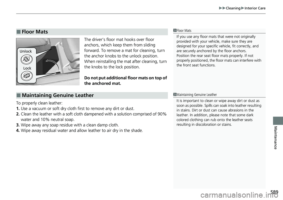
The driver’s floor mat hooks over floor
anchors, which keep them from sliding
forward. To remove a mat for cleaning, turn
the anchor knobs to the unlock position.
When reinstalling the mat after cleaning, turn
the knobs to the lock position.
Do not put additional floor mats on top of
the anchored mat.
To properly clean leather:
1. Use a vacuum or soft dry cloth first to remove any dirt or dust.
2. Clean the leather with a soft cloth dampen ed with a solution comprised of 90%
water and 10% neutral soap.
3. Wipe away any soap residu e with a clean damp cloth.
4. Wipe away residual water and allo w leather to air dry in the shade.
■Floor Mats1Floor Mats
If you use any floor mats that were not originally
provided with your vehicle, make sure they are
designed for your specific ve hicle, fit correctly, and
are securely anchored by the floor anchors.
Position the rear seat floor mats properly. If not
properly positioned, the floor mats can interfere with
the front seat functions.
Lock
Unlock
■Maintaining Genuine Leather1
Maintaining Genuine Leather
It is important to clean or wipe away dirt or dust as
soon as possible. Spills can soak into leather resulting
in stains. Dirt or dust ca n cause abrasions in the
leather. In addition, pl ease note that some dark
colored clothing can rub onto the leather seats
resulting in discol oration or stains.
Page 604 of 657

uuIf a Tire Goes Flat uChanging a Flat Tire
602
Handling the Unexpected
1. Remove the center cap.
2. Place the flat tire face down in the spare tire
well.
3. Remove the spacer cone from the wing
bolt, flip it over, and insert it back on the
bolt. Secure the flat tire with the wing bolt.
4. Securely put the jack and wheel nut wrench
back in the tool case. Store the case in the
trunk.
If you replace a flat tire with the spare tire, the low tire pressure/TPMS indicator
comes on while you are driving. Afte r driving for a few miles (kilometers), Tire
Pressure Monitor System Problem. Ch eck Tire Pressure. See Your Dealer. will
appear on the driver information interface and the indicator will start blinking for a
short time and then stay on; however, this is normal and is no cause for concern.
Calibrate the TPMS when you replace the tire with a specified regular tire.
2TPMS Calibration P. 446
■Storing the Flat Tire1Storing the Flat Tire
3WARNING
Loose items can fly around the interior in a
crash and can seriously injure the
occupants.
Store the wheel, jack, and tools securely
before driving.
Center Cap
Spacer Cone
Wing Bolt
For
compact
spare tire For
full-size
tire
■TPMS and the Compact Spare Tire
Page 608 of 657

606
Handling the Unexpected
If the Battery Is Dead
Jump Starting Procedure
Turn off the power to electric devices, such as audio and lights. Turn off the engine,
then open the hood. 1.Open the cover on the positive + terminal.
2. Connect the first jump er cable to your
vehicle’s battery + terminal.
3. Connect the other end of the first jumper
cable to the booster battery + terminal.
u Use a 12-volt booster battery only.
u When using an automotive battery
charger to boost your 12-volt battery,
select a lower charging voltage than
15-volt. Check the charger manual for
the proper setting.
4. Connect the second jumper cable to the
booster battery - terminal.1If the Battery Is Dead
Securely attach the jumper cables clips so that they
do not come off when the e ngine vibrates. Be careful
not to tangle the jumper cables or allow the cable
ends to touch each other while attaching or
detaching the jumper cables.
3WARNING
A battery can explode if you do not follow
the correct procedure, seriously injuring
anyone nearby.
Keep all sparks, open flames, and smoking
materials away from the battery.
Booster Battery
1.5 L engine models
2.0 L engine models
Booster Battery
Page 623 of 657

621
uuFuses uFuse Locations
Continued
Handling the Unexpected
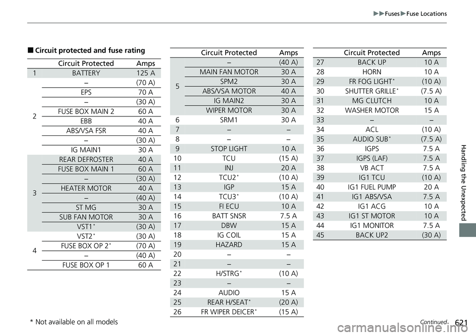
■Circuit protected and fuse rating
Circuit ProtectedAmps
1BATTERY125 A
2
−(70 A)
EPS70 A
−(30A)
FUSE BOX MAIN 260 A
EBB40 A
ABS/VSA FSR 40 A −(30A)
IG MAIN1 30 A
3
REAR DEFROSTER40 A
FUSE BOX MAIN 160 A
−(30 A)
HEATER MOTOR40 A
−(40 A)
ST MG30 A
SUB FAN MOTOR30 A
VST1*(30 A)
4 VST2*(30 A)
FUSE BOX OP 2*(70 A)
−(40A)
FUSE BOX OP 1 60 A
5
−(40 A)
MAIN FAN MOTOR30 A
SPM230 A
ABS/VSA MOTOR40 A
IG MAIN230 A
WIPER MOTOR30 A
6SRM1 30A
7−−
8− −
9STOP LIGHT10 A
10 TCU (15 A)
11INJ20 A
12 TCU2*(10 A)
13IGP15 A
14 TCU3*(10 A)
15FI ECU10 A
16 BATT SNSR 7.5 A
17DBW15 A
18 IG COIL 15 A
19HAZARD15 A
20 − −
21−−
22 H/STRG*(10 A)
23−−
24 AUDIO 15 A
25REAR H/SEAT*(20 A)
26 FR WIPER DEICER*(15 A)
Circuit ProtectedAmps
27BACK UP10 A
28 HORN 10 A
29FR FOG LIGHT*(10 A)
30 SHUTTER GRILLE*(7.5 A)
31MG CLUTCH10 A
32 WASHER MOTOR 15 A
33−−
34 ACL (10 A)
35AUDIO SUB*(7.5 A)
36 IGPS 7.5 A
37IGPS (LAF)7.5 A
38 VB ACT 7.5 A
39IG1 TCU(10 A)
40 IG1 FUEL PUMP 20 A
41IG1 ABS/VSA7.5 A
42 IG1 ACG 10 A
43IG1 ST MOTOR10 A
44 IG1 MONITOR 7.5 A
45BACK UP2(30 A)
Circuit ProtectedAmps
* Not available on all models