2022 FORD F-650/750 jump cable
[x] Cancel search: jump cablePage 119 of 379

•
Incorrect fuel for climatic conditions.
• Incorrect engine oil viscosity for
climactic conditions.
Note: Some vehicles have a lifetime fuel
filter that is integrated with the fuel tank.
Regular maintenance or replacement is not
needed.
Note: If these checks do not help you
correct the concern, have your vehicle
checked as soon as possible.
Noise Emissions Warranty,
Prohibited Tampering Acts and
Maintenance
On January 1, 1978, Federal regulation
became effective governing the noise
emission on trucks over 10,000 lb
(4,536 kg) Gross Vehicle Weight Rating
(GVWR). The preceding statements
concerning prohibited tampering acts and
maintenance, and the noise warranty
found in the Warranty Guide, are
applicable to complete chassis cabs over
10,000 lb (4,536 kg)
GVWR.
CATALYTIC CONVERTER WARNING:
Do not park, idle or
drive your vehicle on dry grass or other
dry ground cover. The emission system
heats up the engine compartment and
exhaust system, creating the risk of fire. WARNING:
The normal operating
temperature of the exhaust system is
very high. Never work around or attempt
to repair any part of the exhaust system
until it has cooled. Use special care when
working around the catalytic converter.
The catalytic converter heats up to a very
high temperature after only a short
period of engine operation and stays hot
after the engine is switched off. WARNING:
Exhaust leaks may
result in entry of harmful and potentially
lethal fumes into the passenger
compartment. If you smell exhaust
fumes inside your vehicle, have your
vehicle inspected immediately. Do not
drive if you smell exhaust fumes.
Your vehicle has various emission control
components and a catalytic converter that
enables it to comply with applicable
exhaust emission standards.
To make sure that the catalytic converter
and other emission control components
continue to work properly:
• Do not crank the engine for more than
10 seconds at a time.
• Do not run the engine with a spark plug
lead disconnected.
• Do not push-start or tow-start your
vehicle. Use booster cables. See Jump
Starting the Vehicle
(page 189).
• Use only the specified fuel listed.
• Do not switch the ignition off when your
vehicle is moving.
• Avoid running out of fuel.
• Have the items listed in scheduled
maintenance information performed
according to the specified schedule.
Note: Resulting component damage may
not be covered by the vehicle Warranty.
The scheduled maintenance items listed
in scheduled maintenance information are
essential to the life and performance of
your vehicle and to its emissions system.
If you use anything other than Ford,
Motorcraft or Ford-authorized parts for
maintenance replacements or for service
of components affecting emission control,
such non-Ford parts should be equivalent
to genuine Ford Motor Company parts in
performance and durability.
116
2022 F650750 (TBC) , enUSA, Edition date: 202010, Second-Printing Engine Emission Control
Page 192 of 379

JUMP STARTING THE VEHICLE
WARNING: Batteries normally
produce explosive gases which can
cause personal injury. Therefore, do not
allow flames, sparks or lighted
substances to come near the battery.
When working near the battery, always
shield your face and protect your eyes.
Always provide correct ventilation. WARNING:
Keep batteries out of
reach of children. Batteries contain
sulfuric acid. Avoid contact with skin,
eyes or clothing. Shield your eyes when
working near the battery to protect
against possible splashing of acid
solution. In case of acid contact with skin
or eyes, flush immediately with water for
a minimum of 15 minutes and get prompt
medical attention. If acid is swallowed,
call a physician immediately. WARNING:
Use only adequately
sized cables with insulated clamps.
Preparing Your Vehicle
Do not attempt to push-start your
automatic transmission vehicle.
Note: Attempting to push-start a vehicle
with an automatic transmission may cause
transmission damage.
Note: Use only a 12-volt supply to start your
vehicle.
Note: Do not disconnect the battery of the
disabled vehicle as this could damage the
vehicle electrical system.
Park the booster vehicle close to the hood
of the disabled vehicle, making sure the
two vehicles do not touch. Connecting the Jumper Cables WARNING:
Do not attach the
cables to fuel lines, engine rocker covers,
the intake manifold or electrical
components as grounding points. Stay
clear of moving parts. To avoid reverse
polarity connections, make sure that you
correctly identify the positive (+) and
negative (-) terminals on both the
disabled and booster vehicles before
connecting the cables. WARNING:
Do not attach the end
of the positive cable to the studs or
L-shaped eyelet located above the
positive (+) terminal of your vehicle ’s
battery. High current may flow through
and cause damage to the fuses. WARNING: Do not connect the end
of the second cable to the negative (-)
terminal of the battery to be jumped. A
spark may cause an explosion of the
gases that surround the battery.
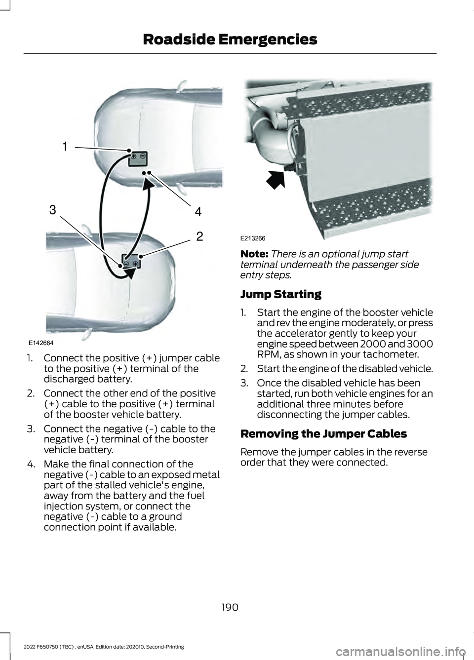
Note: In the illustration, the bottom vehicle
represents the booster vehicle.
189
2022 F650750 (TBC) , enUSA, Edition date: 202010, Second-Printing Roadside Emergencies
Page 193 of 379

1.
Connect the positive (+) jumper cable
to the positive (+) terminal of the
discharged battery.
2. Connect the other end of the positive (+) cable to the positive (+) terminal
of the booster vehicle battery.
3. Connect the negative (-) cable to the negative (-) terminal of the booster
vehicle battery.
4. Make the final connection of the negative (-) cable to an exposed metal
part of the stalled vehicle's engine,
away from the battery and the fuel
injection system, or connect the
negative (-) cable to a ground
connection point if available. Note:
There is an optional jump start
terminal underneath the passenger side
entry steps.
Jump Starting
1. Start the engine of the booster vehicle
and rev the engine moderately, or press
the accelerator gently to keep your
engine speed between 2000 and 3000
RPM, as shown in your tachometer.
2. Start the engine of the disabled vehicle.
3. Once the disabled vehicle has been started, run both vehicle engines for an
additional three minutes before
disconnecting the jumper cables.
Removing the Jumper Cables
Remove the jumper cables in the reverse
order that they were connected.
190
2022 F650750 (TBC) , enUSA, Edition date: 202010, Second-Printing Roadside Emergencies4
2
1
3
E142664 E213266
Page 194 of 379

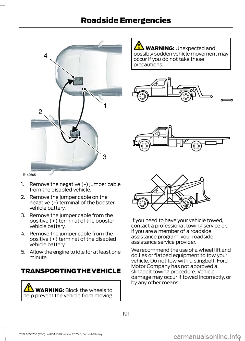
1. Remove the negative (-) jumper cable
from the disabled vehicle.
2. Remove the jumper cable on the negative (-) terminal of the booster
vehicle battery.
3. Remove the jumper cable from the positive (+) terminal of the booster
vehicle battery.
4. Remove the jumper cable from the positive (+) terminal of the disabled
vehicle battery.
5. Allow the engine to idle for at least one
minute.
TRANSPORTING THE VEHICLE WARNING: Block the wheels to
help prevent the vehicle from moving. WARNING:
Unexpected and
possibly sudden vehicle movement may
occur if you do not take these
precautions. If you need to have your vehicle towed,
contact a professional towing service or,
if you are a member of a roadside
assistance program, your roadside
assistance service provider.
We recommend the use of a wheel lift and
dollies or flatbed equipment to tow your
vehicle. Do not tow with a slingbelt. Ford
Motor Company has not approved a
slingbelt towing procedure. Vehicle
damage may occur if towed incorrectly, or
by any other means.
191
2022 F650750 (TBC) , enUSA, Edition date: 202010, Second-Printing Roadside Emergencies4
1
3
2
E142665 E143886
Page 256 of 379

2. Reconnect the fuel lines.
3. Switch the ignition on for 30 seconds
and then switch the ignition off.
Repeat this operation six times in a row
to purge any trapped air from the fuel
system.
ELECTRICAL SYSTEM
INSPECTION
Periodically inspect electrical connectors
on the outside of the cab and on the engine
and frame for corrosion and tightness.
Exposed terminals, such as the fuel sender,
cranking motor, alternator and
feed-through studs, should be cleaned and
re-coated with a lubricant sealing grease
such as Motorcraft Silicone Brake Caliper
Grease and Dielectric Compound XG-3, or
equivalent. This should include the ground
cable connector for batteries, engine and
cab as well as the jump-starting stud.
Accessory Feed Connections
Vehicle electrical systems are complex and
often include powertrain components,
such as engine and transmission controls,
instrument panels and ABS. While most
systems operate on battery voltage (12
volts), some systems can be as high as 90
volts or as low as five volts. See the
Electrical Circuit Diagram Manuals,
available from your vehicle ’s manufacturer,
to make sure that any extra body lights and
accessory connections to circuits are both
appropriate and not overloaded. Do not
make modifications to any vehicle control
system without first contacting an
authorized dealer. AIR INDUCTION SYSTEM
INSPECTION WARNING: When performing
maintenance to any turbocharged engine
with engine air inlet piping disconnected,
keep loose clothing, jewelry and long hair
away from the engine air inlet piping. A
turbocharger compressor air inlet
protective shield should be installed over
the turbocharger air inlet to reduce the
risk of personal injury or death.
Perform a complete inspection of the air
induction system annually.
In areas where road salt is used,
disassemble the joints of each aluminum
component and inspect for salt build-up
and presence of chlorine that can cause
aluminum particles to flake off and enter
the engine combustion chambers. If
evidence of corrosion is found (usually at
the pipe connections), use a wire brush to
clean the inside of the pipes and inside the
rubber hoses.
If pitting is evident at the joint ends of the
intake pipes, use Motorcraft Silicone
Gasket and Sealant TA-30 to seal the
joints. Make sure no excess material, which
can pull into the engine, is on the inside of
the pipes. If the service condition of the
pipes, hoses or clamps is questionable,
replace the defective part(s).
Make sure to clean all dust and debris out
of the pipes and couplings with a clean,
damp rag before reassembly.
Chassis-mounted Charge Air
Cooler
Visually inspect the core assembly for
debris and clogging of external fins with
the engine off.
253
2022 F650750 (TBC) , enUSA, Edition date: 202010, Second-Printing Maintenance